After the Spring break activities finished here, I updated my schedule for ZinnBee Lego-lab ML testing report, which will be posted by end of this week. I jumped to communication testing between Arduino Nicla Vision module and MKR 1310 module now.
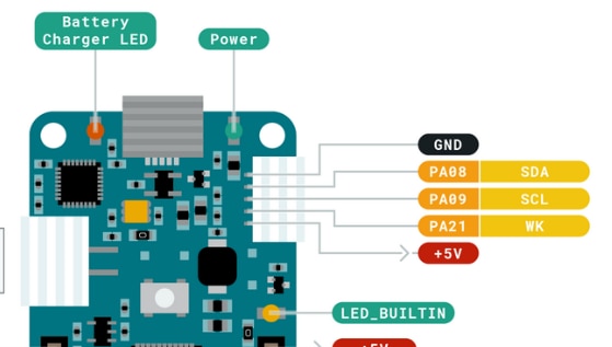
I connected Arduino Nicla Vision module J5(I2C bus) with MKR 1310 QWIIC JST connector as Fig 1.

Fig 1: MKR 1310 QWIIC JST Connector
The hardware bench testing was set up as Fig 2.
Fig 2: I2C Bench Testing Setup Between Nicla Vision Module and MKR1310
The source code of Nicla Vision I2C master was modified from OpenMV example I2C codes as below:
# I2C Control
#
# This example shows how to use the i2c bus on your OpenMV Cam by dumping the
# contents on a standard EEPROM. To run this example either connect the
# Thermopile Shield to your OpenMV Cam or an I2C EEPROM to your OpenMV Cam.

from machine import I2C
i2c = I2C(1,freq=100000)
print(i2c)
#print(i2c.scan())

#address =i2c.scan()[0]
address = 14

print(address)
data = i2c.readfrom(address, 7)
print(data)

i2c.writeto(address,b'000')
I used fixed I2C slave address 14 here in order to simply my I2C bus decode work on the oscilloscope.
The I2C slave source code used Arduino Wire library with very generic
/*
  MKR1310 I2C Slave Demo
  i2c-slave-test.ino
*/

// Include Arduino Wire library for I2C
#include <Wire.h>

// Define Slave I2C Address
#define SLAVE_ADDR 14

// Define Slave answer size
#define ANSWERSIZE 7

// Define string with response to Master
String answer = "MKR1310";

void setup() {

  // Initialize I2C communications as Slave
  Wire.begin(SLAVE_ADDR);

  // Function to run when data requested from master
  Wire.onRequest(requestEvent);

  // Function to run when data received from master
  Wire.onReceive(receiveEvent);

  // Setup Serial Monitor
  Serial.begin(9600);
  Serial.println("I2C Slave from MKR1310");
}

void receiveEvent(int data) {

  // Read while data received
  Serial.println("Receive data: ");
  while (0 < Wire.available()) {
    data  = Wire.read();
  Serial.print(data);
  }
  Serial.println("\n");


}

void requestEvent() {

  // Setup byte variable in the correct size
  byte response[ANSWERSIZE];

  // Format answer as array
  for (byte i=0;i<ANSWERSIZE;i++) {
    response[i] = (byte)answer.charAt(i);
  }

  // Send response back to Master
  Wire.write(response,sizeof(response));

  // Print to Serial Monitor
  Serial.println("Request event");
  Serial.println("\n");
}

void loop() {

  // Time delay in loop
  delay(500);
}
bus control commands.
The bench testing results are presented as below.
1. Nicla Vision I2C bus got proper response from I2C slave as Fig 3: printing out messages received from I2C slave: 'MKR1310' by using I2C slave address 14.
Fig 3: Nicla Vision Working as I2C Master
2. MKR 1310 received message from I2C master as Fig 4: data package was 484848(in Decimal), which is ASCII code for b'000.
Fig 4: MKR1310 as I2C Slave Received Data from I2C Master
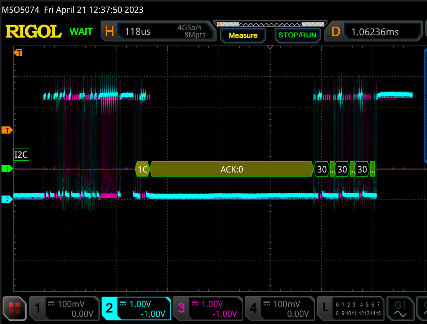
Here is the waveform of I2C bus from the oscilloscope.

Fig 5: I2C Bus Waveform at 100KHz Speed
From this bench testing, I found my Rigol MSO5074 might not decode I2C bus address at a proper way. The address decoded from my Rigol MSO5074 was 1C, which was not 14 as I defined. Nicla Vision module can use I2C slave address 14 without any issues. I will make time to figure out why my Rigol MSO5074 can not decode I2C bus 100%. However, my Rigol MSO5074 was still capable to decode data package in ASCII code properly, which was a plus.
ZinnBee Blogs as below:
ZinnBee Blog#01: Introduction of the Project
ZinnBee Blog#02: Initial Project Structure
ZinnBee Blog#03: LoRa WAN Communication Framework
ZinnBee Blog#04: First Impression of Arduino Nicla Vision Machine Learning Process
