


Recap: I am building a wireless vitals sensor node (heart rate, SpO₂, temperature) that reports over BLE into Home Assistant. This way we smartly keep watch over our loved ones. It is built up in three phases — DK bring-up, a custom miniaturized nRF52832 PCB, then a Matter over Thread proof of concept.
Past Posts
Generic MAX30102 breakout
The sponsored kit is still on it's way, In-fact It is gonna be delivered tomorrow, but I had some spare time and a cheap generic MAX30102 breakout so started firmware bring-up early. Same underlying MAX30102 die as the MAXREFDES117, so It should work the same.
| Pin | Function | Notes |
|---|---|---|
| VIN | Power in | 1.8–5V |
| GND | Ground | |
| SCL | I²C clock | to nRF52832 DK |
| SDA | I²C data | to nRF52832 DK |
| INT | Interrupt output | active-low, open-drain; needs a pull-up |
| IRD | IR LED driver override | Overrise Pin |
| RD | Red LED driver override | Override Pin |
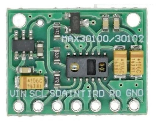
There was one minor difference - the breakout exposes two extra pins, IRD and RD, that the official MAXREFDES117 doesn't have at all. These are manual override test points wired straight to the chip's internal LED driver outputs, for bypassing the chip's own current control and driving the LEDs externally. Left both floating as per https://circuitdigest.com/microcontroller-projects/how-max30102-pulse-oximeter-and-heart-rate-sensor-works-and-how-to-interface-with-arduino
How PPG actually works
The sensor has two LEDs one Red ~660nm wavelength and another Infra-Red with ~880nm wavelength. They shine into the fingertip, and a photodiode on the same side measures how much light comes back. Oxygenated and Deoxygenated blood reflects the light differently. So by measuring the intensity as well as the rhythemic change in Intensity as the heart beats, you can measure the heartreate. Once we get the base line, we move on to the Blood Oxygen. Comparing the AC/DC ratio of the Red channel against the AC/DC ratio of the IR channel gives a value that gives us the blood oxygen saturation.
Interfacing the Sensor
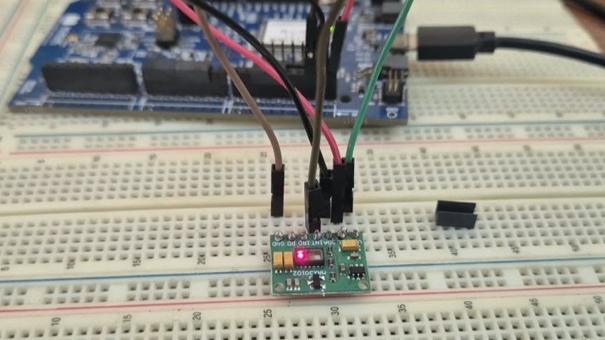
When the sensor is I2C, the easiest way to break ice is with an I2C Scanner, Thankfully, the sensor was not shy and responded ACK to my scan.
Then I wrote a register readback test: set LED1_PA (Red) and LED2_PA (IR) alternately, reading each register back after every write to confirm the write. Red flashing was visible by eye; IR was not visible, So I took it for granted.
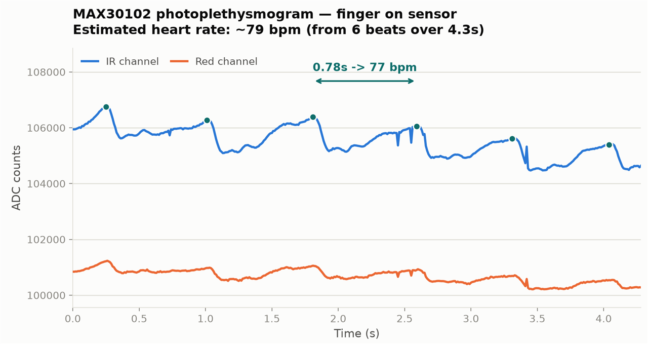
Next was draining the sensor's FIFO continuously and logging raw Red/IR sample pairs. The raw PPG data streamed cleanly, and a plain peak-counting script on the captured trace estimated ~78 BPM
Porting SparkFun's Library
I used SparkFun's spo2_algorithm which is an derivative of Maxim's original MAXREFDES117 reference algorithm/
It has one entry point.
void maxim_heart_rate_and_oxygen_saturation(
    uint32_t *pun_ir_buffer, int32_t n_ir_buffer_length,
    uint32_t *pun_red_buffer,
    int32_t *pn_spo2, int8_t *pch_spo2_valid,
    int32_t *pn_heart_rate, int8_t *pch_hr_valid
);
You hand it a buffer of IR samples and a buffer of Red samples (BUFFER_SIZE, which is FreqS * 4 — 4 seconds' worth at whatever sample rate FreqS is set to, 25Hz by default), and it hands back a heart rate and an SpO₂ estimate, each with its own valid flag.
Heart rate comes from straightforward valley detection on the IR trace:
// calculates DC mean and subtract DC from ir
un_ir_mean = 0;
for (k = 0; k < n_ir_buffer_length; k++) un_ir_mean += pun_ir_buffer[k];
un_ir_mean = un_ir_mean / n_ir_buffer_length;

// remove DC and invert signal so that we can use peak detector as valley detector
for (k = 0; k < n_ir_buffer_length; k++)
  an_x[k] = -1 * (pun_ir_buffer[k] - un_ir_mean);

// 4 pt Moving Average
for (k = 0; k < BUFFER_SIZE - MA4_SIZE; k++) {
  an_x[k] = (an_x[k] + an_x[k+1] + an_x[k+2] + an_x[k+3]) / (int)4;
}
Subtract the DC baseline, invert the signal, smooth it with a 4-point moving average, then run a peak finder on the inverted trace — since a pulse is a dip followed by a rise in raw IR, flipping it turns valleys into peaks so the same peak finder can be reused. Peak spacing directly gives heart rate: (FreqS * 60) / average_samples_between_peaks.
SpO2 is the part that actually needs both LED colors: it finds the AC and DC component of both the Red and IR channel between consecutive valleys, computes their ratio, and looks the result up in a precomputed table (uch_spo2_table, 184 entries) rather than evaluating a curve-fit formula directly — the comment in the original source says this is because register overflow made the direct formula inaccurate on the small microcontrollers (Arduino Uno / ARM M0/M3) it originally targeted.
The actual port is as below
// spo2_algorithm.h — before (Arduino):
#include <Arduino.h>
...
const uint8_t uch_spo2_table[184] = { ... };
static int32_t an_x[BUFFER_SIZE];
static int32_t an_y[BUFFER_SIZE];

// after (bare-metal, this repo):
#include <stdint.h>
#ifndef min
#define min(x,y) ((x) < (y) ? (x) : (y))
#endif
...
static const uint8_t uch_spo2_table[184] = { ... };   // static added
static int32_t an_x[BUFFER_SIZE] __attribute__((unused));  // silences -Werror
static int32_t an_y[BUFFER_SIZE] __attribute__((unused));  // in the non-owning TU
Wiring it into the firmware meant configuring the sensor to actually produce 25Hz-equivalent samples from the raw ADC that runs at 100sps, then feeding it with SparkFun's own reference example's sliding-window pattern rather than a fresh buffer each time:
// initial 4-second (100-sample) fill, once
for (int32_t i = 0; i < BUFFER_SIZE; i++)
    max30102_collect_one_sample(&red_buffer[i], &ir_buffer[i]);

maxim_heart_rate_and_oxygen_saturation(ir_buffer, BUFFER_SIZE, red_buffer,
    &spo2, &spo2_valid, &heart_rate, &hr_valid);

while (true) {
    // drop the oldest 25 samples (1s), shift the remaining 75 down
    for (int32_t i = 25; i < BUFFER_SIZE; i++) {
        red_buffer[i - 25] = red_buffer[i];
        ir_buffer[i - 25]  = ir_buffer[i];
    }
    // collect 25 new samples (1s) to refill the window
    for (int32_t i = BUFFER_SIZE - 25; i < BUFFER_SIZE; i++)
        max30102_collect_one_sample(&red_buffer[i], &ir_buffer[i]);

    maxim_heart_rate_and_oxygen_saturation(ir_buffer, BUFFER_SIZE, red_buffer,
        &spo2, &spo2_valid, &heart_rate, &hr_valid);
}
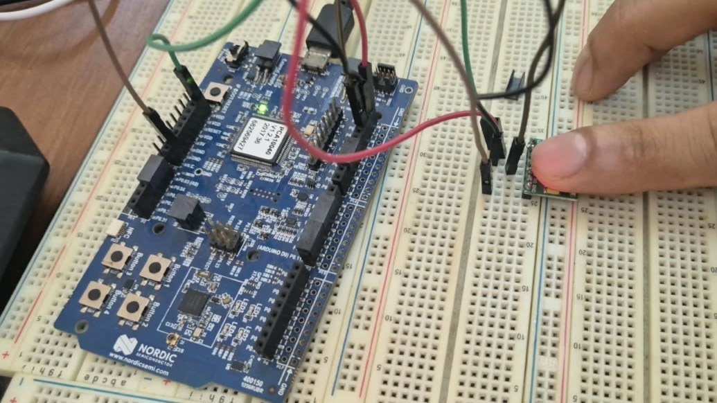
With finger on sensor: Sp02 locked at 98–100%, HR settling around 70–90 BPM which means I made productive use of the spare time.
What's next
MAX30208 (temperature) bring-up is the next item. I should also check if the MAXREFDES117 also works with the same code and compare it with an actual PPG device.


