


EdgeCare: phase 1 - setup IDE, MCU and BLE - element14 Community
EdgeCare will be a Multi-Sensor Metabolic & Autonomic Datalogging Wearable with LabVIEW R&D Analytics.
In this port I will explain the connection of MAX30100 to the main ESP32C6,through I2C, issues with this sensor and how the data are displayed on VI created on LabView.
First thing: ESP32C6 pinout;
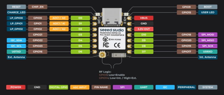 This picture is taken from the official Xiao site: Getting Started with Seeed Studio XIAO ESP32C6 | Seeed Studio Wiki
To use the built in I2C interface, we need to connect the MAX30100 to the following pins:
I2C SDA --> GPIO22 / D4
I2C SCL --> GPIO23 / D5
From master, the data format is simple:
    char dataBuffer[80];
    snprintf(dataBuffer, sizeof(dataBuffer), "%lu,%.1f,%d,%d,%d,%u",
             counter++, dummyTemp, (int)realHR, (int)dummyGSR, (int)dummyTau, realSpO2);
In order to cover future modifications of the data structure, I set the the MTU (Maximum Transmission Unit) to 512 on both master and client BLE:
BLEDevice::setMTU(512);
For the moment, the master sent to the client the following data:
counter --> used to count the nimber of sending jthe data;
dummy Temp --> randon value (will be replaced with the value from real sensor);
realHR --> real value of Heart Rate, from MAC30100;
dummy DSG --> randon value (will be replaced with the value from real sensor);
dummy Tau --> randon value (will be replaced with the value from real sensor);
real SpO2 --> real value of SpO2, from MAX30100.
In LabView, I create a simple panel with some indicators; some of them are only for debugging and will be eliminated in the final instrument:
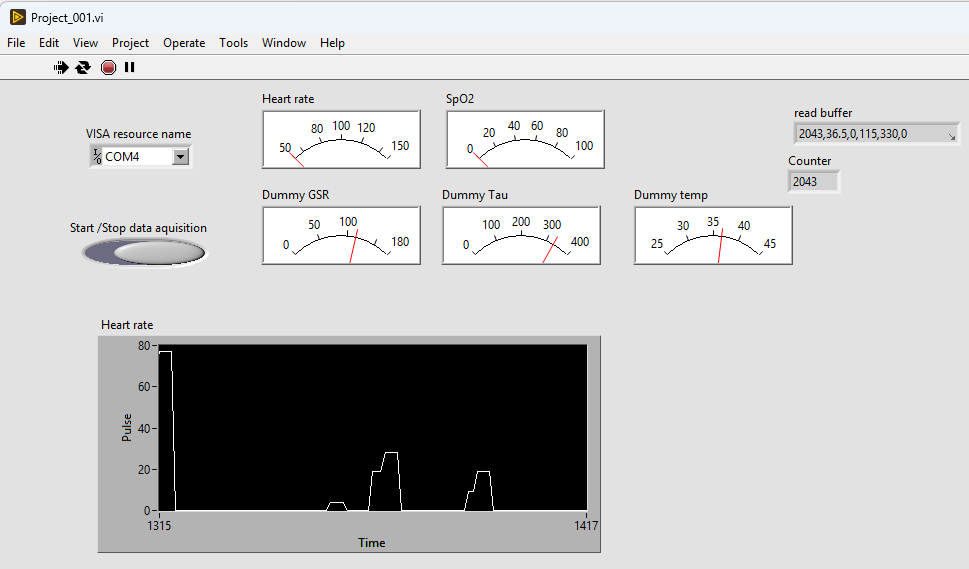
How its working until now:
OBS: I have an issues with my MAX30100 sensor: the pull-up rezistors for I2C communication was not present on the sensor PCB and I have to add them using the soldering iron. After that, the sensor respond correctly to the I2C scanner (for address) and in the main loop.
See you in the next post.
