


The Kit

(" The upper blue roll is the substitute for the thermal tape.
The role on the side is the 3M EM25TP-0050 EMI Absorber.
The big box is the Analog Devices MAX30208EVSYS# Evaluation Kit
The Little black box is the Analog Devices MAXREFDES117# Reference Design Board")
This is the kit, I received it on 23rd but from them I spend time configuring them and in this forum I will show I come up with.
And By the way great thanks to Element14 for the swag :)

Configuring
1) Analog Devices MAX30208EVSYS# Evaluation Kit:
This is the kit:

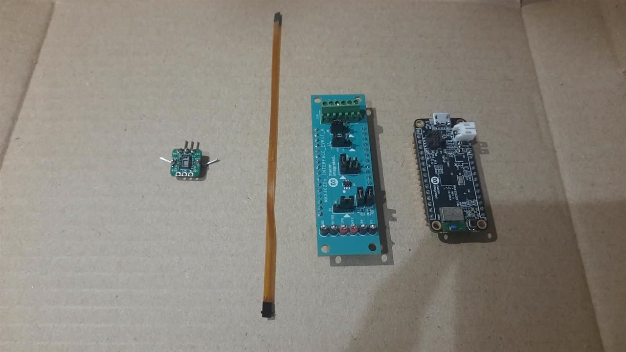
Firstly I tested it with the pre-flashed MAX32630FTHR MCU board, it was surprisingly easy put the MCU in the bottom of the board in J2 and J1, then put the flex ribbon in the J9. If you haven`t altered any caps to switch mode then it will work fine, and If you have messed them a bit. make sure.
Caps are put as in the image

Then go to https://www.analog.com/en/resources/evaluation-hardware-and-software/evaluation-boards-kits/max30208evsys.html#eb-overview and scroll down to bottom and download the the tool.
And open, there is no need to install extra diver. And you will start seeing real time temperature readings Unfortunately the MCU get damaged(while I was testing it with the battery the battery socket had the opposite pins, and there was no diode to protect the internals, I tried my best to find the real damage but nothing was seeming to work, and I decide to leave that for know and else use the Arduino UNO Q as the controller only.  )
)
Using it with our own platform
I was not able to find the frimware that come preinstalled in the MCU after spending the whole evening also.
But with the I had taken a screenshot of the registered address so I was able to reconstruct the sketch.

Else if your are using my code you do not need this to configure it.
Wire as shown(using J10):
GPIO1/3 -> EMPTY
SDA/GPIO2 -> To your MCU`s SDA
SCL/GPIO1 ->To your MCU`s SDA
VDD/DQ -> 3.3v
GND -> GND
This is how I implement the addresses.
// --- MAX30208 Register Definitions ---
#define MAX30208_I2C_ADDR    0x50  // Default address you will get this if you run a i2c scan
#define REG_STATUS           0x00  // Status register
#define REG_FIFO_DATA        0x08  // FIFO temperature data register
#define REG_TEMP_SETUP       0x14  // Temperature setup register (CONVERT_T)
#define REG_PART_ID          0xFF  // Part ID register (Expected value: 0x30)
Reading the data
float readTemperature() {
  // 1. Trigger single-shot conversion (write CONVERT_T bit in reg 0x14)
  Wire.beginTransmission(MAX30208_I2C_ADDR);
  Wire.write(REG_TEMP_SETUP);
  Wire.write(0xC1);
  if (Wire.endTransmission() != 0) {
    return -999.0f; // Communication error
  }

  // 2. Wait for conversion completion (~15ms typical according to MAX30208 datasheet)
  delay(20);

  // 3. Pointer setup to read 2 bytes from FIFO_DATA register (0x08)
  Wire.beginTransmission(MAX30208_I2C_ADDR);
  Wire.write(REG_FIFO_DATA);
  if (Wire.endTransmission(false) != 0) {
    return -999.0f;
  }

  // 4. Request 2 bytes (MSB and LSB)
  Wire.requestFrom((uint8_t)MAX30208_I2C_ADDR, (uint8_t)2);
  if (Wire.available() == 2) {
    uint8_t msb = Wire.read();
    uint8_t lsb = Wire.read();

    // Reconstruct signed 16-bit 2's complement integer
    int16_t rawTemp = (int16_t)((msb << 8) | lsb);

    // Convert LSB to °C (0.005°C scale factor)
    return rawTemp * 0.005f;
  }

  return -999.0f;
}
1. Start Measurement: Tells the MAX30208 sensor to take a temperature reading.
2. Wait: Pauses for 20 ms to let the sensor process.
3. Point to Data: Asks the sensor to open its data register (0x08).
4. Read & Calculate: Reads 2 bytes, combines them into a number, and multiplies by 0.005 to get the temperature in °C.
5. Error Check: Returns -999.0 if any step fails
Results:
Temperature: 31.585 °C  |  88.853 °F
Temperature: 31.645 °C  |  88.961 °F
Temperature: 31.690 °C  |  89.042 °F
Temperature: 31.750 °C  |  89.150 °F
Temperature: 31.820 °C  |  89.276 °F
Temperature: 31.875 °C  |  89.375 °F
Temperature: 31.920 °C  |  89.456 °F
Temperature: 31.925 °C  |  89.465 °F
Temperature: 31.815 °C  |  89.267 °F
Temperature: 31.680 °C  |  89.024 °F
Temperature: 31.510 °C  |  88.718 °F
Temperature: 31.325 °C  |  88.385 °F
Temperature: 31.105 °C  |  87.989 °F
Temperature: 30.920 °C  |  87.656 °F
Temperature: 30.760 °C  |  87.368 °F
Temperature: 30.610 °C  |  87.098 °F
Temperature: 30.475 °C  |  86.855 °F
Temperature: 30.350 °C  |  86.630 °F
Temperature: 30.230 °C  |  86.414 °F
Temperature: 30.135 °C  |  86.243 °F
Temperature: 30.050 °C  |  86.090 °F
Temperature: 29.955 °C  |  85.919 °F
Temperature: 29.890 °C  |  85.802 °F
Temperature: 29.830 °C  |  85.694 °F
Temperature: 29.765 °C  |  85.577 °F
Temperature: 29.710 °C  |  85.478 °F
Temperature: 29.660 °C  |  85.388 °F
Temperature: 29.610 °C  |  85.298 °F
Temperature: 29.565 °C  |  85.217 °F
Temperature: 29.505 °C  |  85.109 °F
Temperature: 29.475 °C  |  85.055 °F
Temperature: 29.425 °C  |  84.965 °F
Temperature: 29.415 °C  |  84.947 °F
Temperature: 29.380 °C  |  84.884 °F
Temperature: 29.350 °C  |  84.830 °F
Temperature: 29.310 °C  |  84.758 °F
Temperature: 29.295 °C  |  84.731 °F
Temperature: 29.280 °C  |  84.704 °F
Temperature: 29.270 °C  |  84.686 °F
Temperature: 29.230 °C  |  84.614 °F
Temperature: 29.215 °C  |  84.587 °F
Temperature: 29.195 °C  |  84.551 °F
Temperature: 29.175 °C  |  84.515 °F
Temperature: 29.170 °C  |  84.506 °F
Temperature: 29.160 °C  |  84.488 °F
Temperature: 29.150 °C  |  84.470 °F
Temperature: 29.180 °C  |  84.524 °F
Finally all the pieces come together and reading started coming (this is the final version of the code that I am showing, I had tried many times and this is the 31st version )
Plotting data in Celsius, it was very smooth with no unexpected noise. In Fahrenheit


2) Analog devices MAXREFDES117#
(in the left most side)
It was surprisingly tiny then expected, after soldering the headers its all done, then we have go to the software part.
The communication method is same as the MAX30208, I2C so connection will be same as it.
GND -> GND
VIN -> 3.3v or 5v (due to the onboard logic level translator)
SCL -> SCL
SDA -> SDA
INT-> To any gpio you want , I am using 4
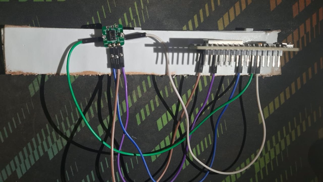
the setup
Firstly I tried to get raw data out of the sensor.
The code:
#include <Wire.h>

// from the i2c scan sensor's address
#define MAX30102_ADDR 0x57

// MAX30102 Register Addresses(from the design files)
#define REG_INTR_STATUS_1 0x00
#define REG_INTR_STATUS_2 0x01
#define REG_INTR_ENABLE_1 0x02
#define REG_INTR_ENABLE_2 0x03
#define REG_FIFO_WR_PTR   0x04
#define REG_OVF_COUNTER   0x05
#define REG_FIFO_RD_PTR   0x06
#define REG_FIFO_DATA     0x07
#define REG_FIFO_CONFIG   0x08
#define REG_MODE_CONFIG   0x09
#define REG_SPO2_CONFIG   0x0A
#define REG_LED1_PA       0x0C
#define REG_LED2_PA       0x0D
#define REG_PILOT_PA      0x10

//optinal pin for multiple devices
#define INT_PIN 4
This section sets up the foundational information the ESP32 needs to talk to the sensor. It includes the Wire.h library, which handles the complex timing of the I2C communication protocol.
It defines the sensor's physical address (0x57), which is like a house number on the I2C bus. Without this, the ESP32 wouldn't know who it's talking to.
It also creates human-readable labels for the sensor's internal memory slots (registers). Finally, it assigns the INT_PIN label to GPIO 4, which is the wire that the sensor will use to tap the ESP32 on the shoulder when it has new data ready.
I developed this code with help of the design file because I was not able to find the datasheet for the board.
// helper function to write to a register
void writeRegister(uint8_t reg, uint8_t value) {
  Wire.beginTransmission(MAX30102_ADDR);
  Wire.write(reg);
  Wire.write(value);
  Wire.endTransmission();
}

// helper function to read from a register
uint8_t readRegister(uint8_t reg) {
  Wire.beginTransmission(MAX30102_ADDR);
  Wire.write(reg);
  Wire.endTransmission(false);
  Wire.requestFrom((uint8_t)MAX30102_ADDR, (uint8_t)1);
  if (Wire.available()) {
    return Wire.read();
  }
  return 0;
}
These two functions are shortcuts designed to keep the main code clean. Whenever you want to change a setting on the sensor, the Wire library requires a tedious four-step process of opening a connection, aiming at a register, sending the data, and closing the connection.
The writeRegister function wraps those four steps into one simple command.
Similarly, readRegister handles the multi-step process of asking the sensor for a piece of information and waiting for it to reply, returning the requested byte of data back to you.
void setup() {
  Serial.begin(115200);
  Wire.begin();

  pinMode(INT_PIN, INPUT);

  Serial.println("Initializing MAX30102...");

  // 1. Reset the sensor
  writeRegister(REG_MODE_CONFIG, 0x40);
  delay(100);

  // 2. Initialize with exact settings from the original driver
  writeRegister(REG_INTR_ENABLE_1, 0xc0);
// ... (other configurations)
  writeRegister(REG_PILOT_PA, 0x7f);

  // 3. Clear interrupts to start clean
  readRegister(REG_INTR_STATUS_1);

  Serial.println("Setup complete. Waiting for data...");
}
The setup block runs exactly once when the ESP32 powers on. It starts the serial connection so you can see the text on your computer, and it boots up the I2C hardware pins.
It then sends a specific command (0x40) to reboot the MAX30102 sensor, wiping away any old, corrupted settings.
After the reboot, it fires off a rapid sequence of configurations. These commands turn on the red and infrared LEDs, set the sampling speed to 100 times a second, and adjust the brightness of the LEDs so they can penetrate the skin. Finally, it reads the status register once to clear any leftover alerts, leaving the sensor ready to work.
void loop() {
  // Wait for the interrupt pin to go LOW
  while (digitalRead(INT_PIN) == HIGH) {
    // Block until new data is ready
  }

  // Clear interrupt status registers so the pin goes back HIGH
  readRegister(REG_INTR_STATUS_1);
  readRegister(REG_INTR_STATUS_2);

  // Read 6 bytes of FIFO data (3 bytes Red, 3 bytes IR)
  Wire.beginTransmission(MAX30102_ADDR);
  Wire.write(REG_FIFO_DATA);
  Wire.endTransmission(false);
  Wire.requestFrom((uint8_t)MAX30102_ADDR, (uint8_t)6);
The loop block runs continuously forever. The very first thing it does is get trapped in a while loop, staring at the INT_PIN. The sensor keeps this pin at 3.3V (HIGH) normally, but violently yanks it to 0V (LOW) the exact millisecond it finishes taking a light reading.
Once the pin drops LOW, the code breaks out of the trap. It immediately reads the status registers to acknowledge the alert, which allows the sensor to release the pin back to 3.3V.
Now that the code knows data is ready, it points to the sensor's data storage tank (the FIFO) and formally requests exactly 6 bytes of optical data to be sent over the wire.
  if (Wire.available() == 6) {
    uint32_t red_val = 0;
    uint32_t ir_val = 0;
    uint32_t temp = 0;

    // Read Red LED data
    temp = Wire.read();
    temp <<= 16;
    red_val += temp;
    temp = Wire.read();
    temp <<= 8;
    red_val += temp;
    temp = Wire.read();
    red_val += temp;

    // Read IR LED data
    // ... (same as Red) ...

    // The MAX30102 data is 18-bit, so mask the top bits
    red_val &= 0x03FFFF;
    ir_val &= 0x03FFFF;

    Serial.print("Red: ");
    Serial.print(red_val);
    Serial.print("\tIR: ");
    Serial.println(ir_val);
  }
}
The ESP32 receives the 6 bytes one by one. The sensor's readings are huge numbers, so it has to chop them into three smaller bytes before sending them.
The code grabs the first byte and shifts it 16 places to the left, putting it in the "millions" column. It grabs the second byte and shifts it 8 places, putting it in the "thousands" column. The third byte is added directly as the "ones" column. Adding them all together reconstructs the original massive number for the Red LED. It then repeats this exact puzzle-building process for the IR LED.
Because the sensor's internal measuring tape is only 18 bits long, our 32-bit variables have 14 bits of random garbage at the top. The code applies a bitwise mask (&= 0x03FFFF) to digitally chop off that garbage. Finally, the clean, raw optical numbers are printed to your screen.
After uploading you would see the red led on the sensor glowing, don`t worry if you wire all up and it doesn`t glow because it requires I2C command.
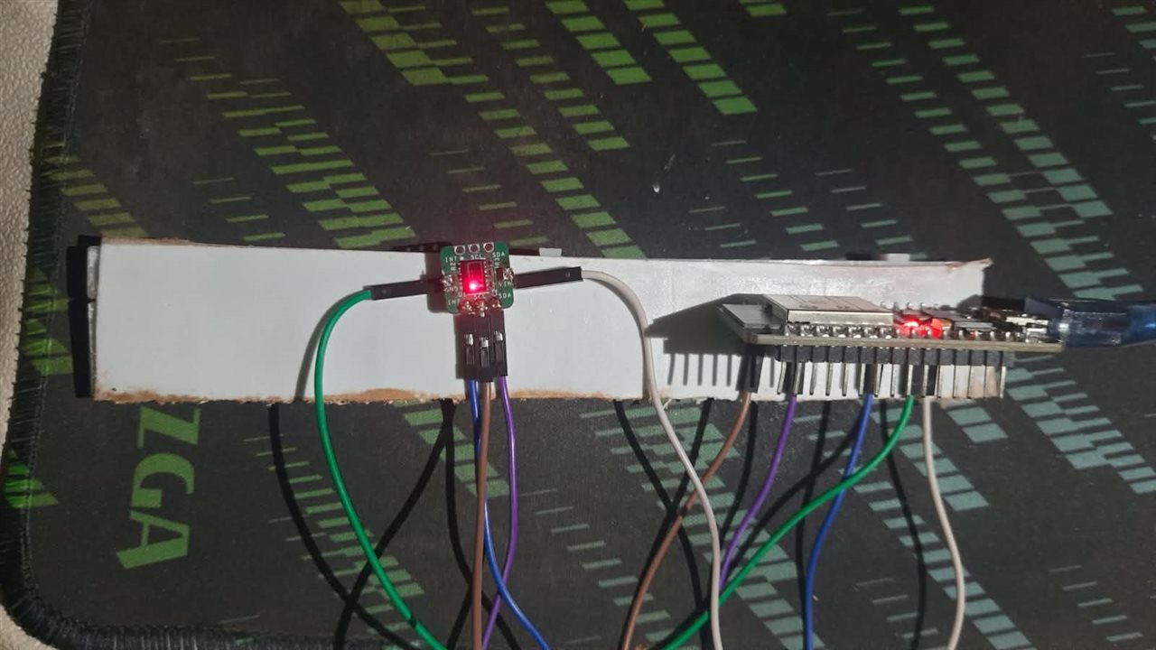
These are the results:
Red: 59081	IR: 53063
Red: 52519	IR: 48219
Red: 58457	IR: 53900
Red: 67719	IR: 62305
Red: 72758	IR: 66136
Red: 71056	IR: 64256
Red: 73083	IR: 66650
Red: 79899	IR: 73915
Red: 87685	IR: 83919
Red: 92788	IR: 91199
Red: 92413	IR: 90605
Red: 83488	IR: 78113
Red: 56625	IR: 50117
Red: 28141	IR: 25406
Red: 9477	IR: 9354
Red: 3063	IR: 3051
Red: 1520	IR: 1404
Red: 1107	IR: 947
Red: 979	IR: 841
Red: 967	IR: 870
Red: 1037	IR: 974
Red: 1067	IR: 1036
Red: 1108	IR: 1105
Red: 1209	IR: 1252
Red: 1328	IR: 1397
Red: 1390	IR: 1487
Red: 1450	IR: 1579
Red: 1481	IR: 1630
Red: 1535	IR: 1682
Red: 1641	IR: 1810
Red: 1750	IR: 1920
Red: 1921	IR: 2113
Red: 2216	IR: 2467
Red: 2425	IR: 2767
Red: 2457	IR: 2824
Red: 2390	IR: 2738
Red: 2272	IR: 2602
Red: 2186	IR: 2501
Red: 2124	IR: 2429
Red: 2128	IR: 2464
Red: 2244	IR: 2603
Red: 2230	IR: 2587
Red: 2141	IR: 2461
Red: 2063	IR: 2338
Red: 2042	IR: 2311
Red: 2041	IR: 2306
They differ from the distance from the sensor and movement of the object relative to the sensor.
This graph shows the noise signal(when the sensor is let undisturbed with nothing in its way)

(DAB I tried using py this time to plot the graph.)
This graph shows readings when the finger is placed with the least possible movement.
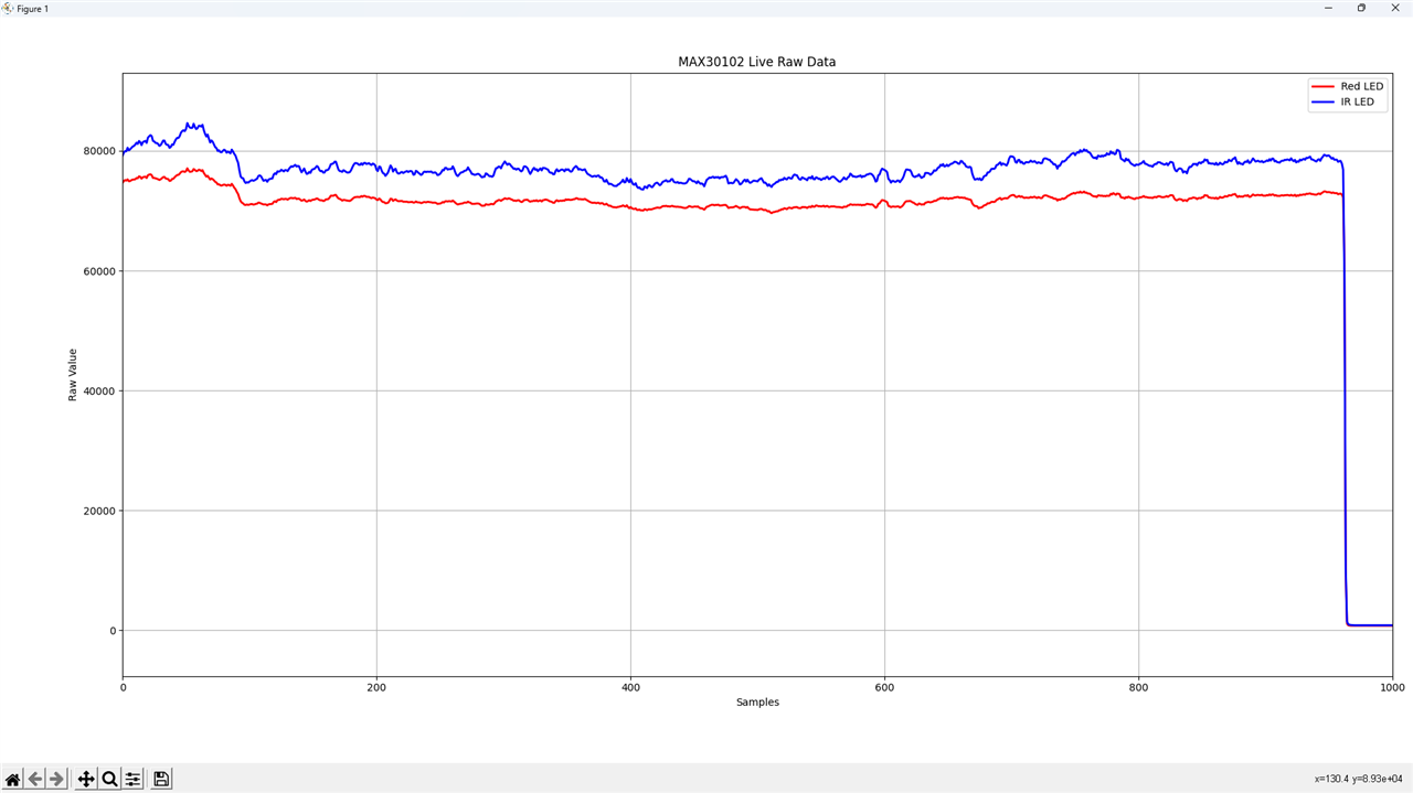
Then, I tried to make the algorithm to convert the raw signal to usable SPO2 and BPM readings but It didn't work quite well so.
So I used the algorithm that was in the design file. And modified it a little bit to suit my needs.
This the code using their algorithm:
#include <Arduino.h>
#include "algorithm.h"
#include "max30102.h"
#include <Wire.h>

#define INT_PIN 4
#define LED_PIN 2

uint32_t aun_ir_buffer[100]; //infrared LED sensor data
uint32_t aun_red_buffer[100];  //red LED sensor data
int32_t n_ir_buffer_length; //data length
int32_t n_spo2;  //SPO2 value
int8_t ch_spo2_valid;  //indicator to show if the SPO2 calculation is valid
int32_t n_heart_rate; //heart rate value
int8_t  ch_hr_valid;  //indicator to show if the heart rate calculation is valid
uint8_t uch_dummy;


// the setup routine runs once when you press reset:
void setup() {
  Wire.begin();
  maxim_max30102_reset(); //resets the MAX30102
  // initialize serial communication at 115200 bits per second:
  Serial.begin(115200);
  pinMode(INT_PIN, INPUT);  //pin connects to the interrupt output pin of the MAX30102
  pinMode(LED_PIN, OUTPUT);
  delay(1000);
  maxim_max30102_read_reg(REG_INTR_STATUS_1,&uch_dummy);  //Reads/clears the interrupt status register
  while(Serial.available()==0)  //wait until user presses a key
  {
    Serial.write(27);       // ESC command
    Serial.print(F("[2J"));    // clear screen command
    Serial.println(F("ESP32"));
    Serial.println(F("Press any key to start conversion"));
    delay(1000);
  }
  uch_dummy=Serial.read();
  maxim_max30102_init();  //initialize the MAX30102
}

// the loop routine runs over and over again forever:
void loop() {
  int32_t i;

  n_ir_buffer_length=100;  //buffer length of 100 stores 4 seconds of samples running at 25sps

  //read the first 100 samples, and determine the signal range
  for(i=0;i<n_ir_buffer_length;i++)
  {
    while(digitalRead(INT_PIN)==1);  //wait until the interrupt pin asserts
    maxim_max30102_read_fifo((aun_red_buffer+i), (aun_ir_buffer+i));  //read from MAX30102 FIFO

    Serial.print(F("red="));
    Serial.print(aun_red_buffer[i], DEC);
    Serial.print(F(", ir="));
    Serial.println(aun_ir_buffer[i], DEC);
  }
  //calculate heart rate and SpO2 after first 100 samples (first 4 seconds of samples)
  maxim_heart_rate_and_oxygen_saturation(aun_ir_buffer, n_ir_buffer_length, aun_red_buffer, &n_spo2, &ch_spo2_valid, &n_heart_rate, &ch_hr_valid);

  //Continuously taking samples from MAX30102.  Heart rate and SpO2 are calculated every 1 second
  while(1)
  {
    i=0;

    //dumping the first 25 sets of samples in the memory and shift the last 75 sets of samples to the top
    for(i=25;i<100;i++)
    {
      aun_red_buffer[i-25]=aun_red_buffer[i];
      aun_ir_buffer[i-25]=aun_ir_buffer[i];
    }

    //take 25 sets of samples before calculating the heart rate.
    for(i=75;i<100;i++)
    {
      while(digitalRead(INT_PIN)==1);
      digitalWrite(LED_PIN, !digitalRead(LED_PIN));
      maxim_max30102_read_fifo((aun_red_buffer+i), (aun_ir_buffer+i));

      //send samples and calculation result to terminal program through UART
      Serial.print(F("red="));
      Serial.print(aun_red_buffer[i], DEC);
      Serial.print(F(", ir="));
      Serial.print(aun_ir_buffer[i], DEC);

      Serial.print(F(", HR="));
      Serial.print(n_heart_rate, DEC);

      Serial.print(F(", HRvalid="));
      Serial.print(ch_hr_valid, DEC);

      Serial.print(F(", SPO2="));
      Serial.print(n_spo2, DEC);

      Serial.print(F(", SPO2Valid="));
      Serial.println(ch_spo2_valid, DEC);
    }
    maxim_heart_rate_and_oxygen_saturation(aun_ir_buffer, n_ir_buffer_length, aun_red_buffer, &n_spo2, &ch_spo2_valid, &n_heart_rate, &ch_hr_valid);
  }
}
It pulls in standard Arduino libraries along with Maxim's sensor driver and algorithm header files to handle the signal processing math behind calculating SpO2 and pulse rates.
When the ESP32 powers on, it sets up the I2C bus, resets the sensor, and prepares the interrupt and LED pins. It holds off on reading data until you press a key in the Serial Monitor, giving you time to open the terminal. Once triggered, it initializes the sensor settings and collects an initial set of 100 samples about 4 seconds worth of red and infrared light readings—to calculate your baseline heart rate and blood oxygen percentage.
After that baseline is set, the code enters an infinite loop using a sliding window technique. Every second, it discards the oldest 25 samples, shifts the remaining 75 samples forward, and fills the gap with 25 fresh readings. With every new sample read, it flashes an onboard LED and streams the optical raw values, heart rate, SpO2, and accuracy validity flags back to your serial console. Once the batch of 25 new samples is captured, it reruns the calculation algorithm to keep your vitals updated in real time.
These are the readings : (I tried my best to make keep my finger consistent but there was still a little bit shake, so I was not able to achieve high accuracy, I will improve this in the upcoming posts.)
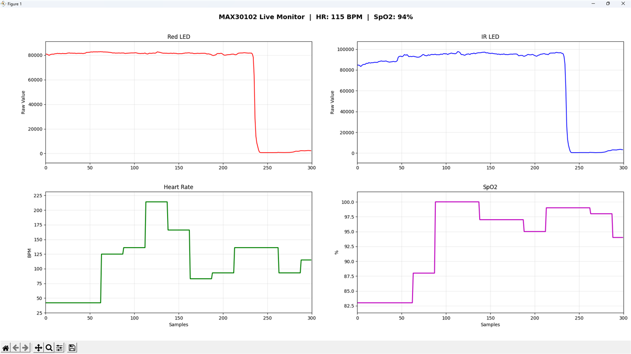
I have tested it on the Esp32 for now but the final version will be with the Arduino UNO Q. And you can checkout https://www.analog.com/media/en/technical-documentation/data-sheets/max30208-ev-sys.pdf for more details.
In the next post I will configure the Arduino UNO Q, MM wave radar sensor and the E- ink display and MPU6500(I have added to further enhance my project). Firstly I had decided to finish it in this post only, but I wasted a lot of time resolving the issue with the MAX32630FTHR MCU board, but I still was not able to resolve it. Do you faced the same issue with the MAX32630FTHR MCU board, your help will matter a lot.
And at last there is the question, Am I allowed to not use the MAX32630FTHR MCU board or I had to buy new one in order to qualify, because I had damaged it.
Thank you for giving your time reading it!

