


In Part 5, I'll interface an 4x4 Tactile Keypad without using an external library
Recap:
The idea is simple enough: stop making people swipe a card and type a PIN at every single door. Instead, the ID card (a MAX32630FTHR + ATECC508A in your pocket) unlocks once via PIN, then silently does challenge-response crypto over Bluetooth every time you walk up to a door. If the card gets yanked off you, the IMU detects the tug and it locks itself. No PIN, no entry. For more details check the Part 1 of the series
- Identity Protocol Part 1 - Plan
- Identity Protocol - Part 2 - Django Server
- Identity Protocol - Part 3 - Unboxing and Blinking with Maxim LPSDK
- Identity Protocol - Part 4 - BLE using PAN1326B and BTstack
For my ID Card device i need a way to enter the pin in order to unlock it, I initially thought of a membrane keyboard, but in my box of electronics treasure, I found an tactile keyboard which i had bought before from Robu: https://robu.in/product/4x4-matrix-16-keyboard-keypad/ and an datasheet attached to it.

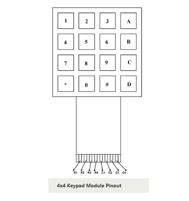
But when i tried with the code, it was not working well, the letter orientation came such that it seemed the rows and columns were transposed. Swapping the pins for Rows and Columns worked. Confusion set it, is my simple enough code wrong? Revelation set in when Adafruit's learning page showed the correct pin out here: https://learn.adafruit.com/matrix-keypad/pinouts . My Code is right, the datasheet was wrong. Here is the correct one

Photo Credits: Adafruit (Do note my code uses C0~C3 instead of C1~C4) and similarly for the Rows
Working of Keypad
The working of keypad is an age old and proven mechanism. Each key is a switch, one side of the switch is wired along the column and the other side is wired along the row. When switch is pressed, it connects the respective column to the row. To detect the key pressed, we wire the 4 Row and 4 Columns pins to GPIO

Photo Credits: Adafruit
- All the Rows are made input without any pull-ups / pull downs (HiZ - High impedance). The Columns are made input with pull ups
- One Row (lets saw R1) is driven low and the 4 columns are read to see which one is low. The column corresponding to the key pressed will be low.
- If no Column is found to be low, the next Row is made low after restoring the previous row to HiZ
- If all rows are scanned and no columns are found low, then it means no key is pressed
When One key is found to be pressed, It is saved in key and last key. During the next round of scan if the same key is found to be still pressed, it is ignored. This way i have implemented a simple hold detection. This happens until the the scan finds no key pressed, but last key is set, this signals a key release event, and last_key is set as none. a 10ms interval between scans should be sufficient for the de-bouncing delay. If you don't know what de-bouncing is check out https://www.picotech.com/library/articles/blog/what-is-switch-bounce-how-to-implement-debounce
In my implementation of this as a function - keypad_scan() it returns an integer such that the number starts from 0 and increases as keys go from top to bottom and left to right. This way i can quickly compare the pressed key to the last one in one statement, plus also is easier to debug in case a key / row / column is not working
1=0   2=1   3=2   A=3
4=4   5=5   6=6   B=7
7=8   8=9   9=10  C=11
*=12  0=13  #=14  D=15
Flow Chart of working

Keypad Wiring
| Signal | Pin |
| KPD_ROW0 | P5_0 |
| KPD_ROW1 | P5_1 |
| KPD_ROW2 | P5_2 |
| KPD_ROW3 | P5_3 |
| KPD_COL0 | P5_4 |
| KPD_COL1 | P5_6 |
| KPD_COL2 | P3_2 |
| KPD_COL3 | P3_3 |
The Results

This one is in a gif format. Below is the full video (there might be a video sync issue between the screen capture and the video of me pressing the button)
Source Code
#include <stdio.h>
#include "mxc_errors.h"
#include "gpio.h"
#include "tmr_utils.h"
#include "uart.h"

/* ---- Board_Init override ------------------------------------------------- */
int Board_Init(void) { return E_NO_ERROR; }

/* ---- Keypad configuration ------------------------------------------------ */
#define KEYPAD_ROWS  4
#define KEYPAD_COLS  4

/* Row pins: P5_0, P5_1, P5_2, P5_3 (SPI header pins, no SPI peripheral on ID device) */
static const gpio_cfg_t row_cfg[KEYPAD_ROWS] = {
    { PORT_5, PIN_0, GPIO_FUNC_GPIO, GPIO_PAD_NORMAL },
    { PORT_5, PIN_1, GPIO_FUNC_GPIO, GPIO_PAD_NORMAL },
    { PORT_5, PIN_2, GPIO_FUNC_GPIO, GPIO_PAD_NORMAL },
    { PORT_5, PIN_3, GPIO_FUNC_GPIO, GPIO_PAD_NORMAL },
};

/* Column pins: P5_4, P5_6, P3_2, P3_3 -- input with internal pull-up */
static const gpio_cfg_t col_cfg[KEYPAD_COLS] = {
    { PORT_5, PIN_4, GPIO_FUNC_GPIO, GPIO_PAD_INPUT_PULLUP },
    { PORT_5, PIN_6, GPIO_FUNC_GPIO, GPIO_PAD_INPUT_PULLUP },
    { PORT_3, PIN_2, GPIO_FUNC_GPIO, GPIO_PAD_INPUT_PULLUP },
    { PORT_3, PIN_3, GPIO_FUNC_GPIO, GPIO_PAD_INPUT_PULLUP },
};

#define KEY_NONE  -1   /* no key detected this scan, cant use 0 */

/* Key label lookup: row-major, matches physical layout
 *   Row 0: 1 2 3 A
 *   Row 1: 4 5 6 B
 *   Row 2: 7 8 9 C
 *   Row 3: * 0 # D
 */
static const char key_map[KEYPAD_ROWS][KEYPAD_COLS] = {
    { '1', '2', '3', 'A' },
    { '4', '5', '6', 'B' },
    { '7', '8', '9', 'C' },
    { '*', '0', '#', 'D' },
};

/*
 * keypad_init -- configure all row pins as outputs (high), all col pins as
 * inputs with pull-ups.
 */
static void keypad_init(void)
{
    for (int r = 0; r < KEYPAD_ROWS; r++) {
        GPIO_Config(&row_cfg[r]);
        GPIO_OutSet(&row_cfg[r]);   /* idle high */
    }
    for (int c = 0; c < KEYPAD_COLS; c++) {
        GPIO_Config(&col_cfg[c]);
    }
}

/*
 * keypad_scan -- drive each row low in turn, read columns, restore row.
 * Returns encoded key index (row*4+col) or KEY_NONE.
 *
 * Rows not being scanned are set to input (high-Z) to avoid bus contention
 * when multiple keys are wired to the same column.
 */
static int keypad_scan(void)
{
    for (int r = 0; r < KEYPAD_ROWS; r++) {
        /* Set all rows to input (high-Z) */
        for (int i = 0; i < KEYPAD_ROWS; i++) {
            gpio_cfg_t hi_z = row_cfg[i];
            hi_z.func = GPIO_FUNC_GPIO;
            hi_z.pad  = GPIO_PAD_INPUT;
            GPIO_Config(&hi_z);
        }

        /* Drive the target row low (output) */
        gpio_cfg_t out = row_cfg[r];
        out.func = GPIO_FUNC_GPIO;
        out.pad  = GPIO_PAD_NORMAL;
        GPIO_Config(&out);
        GPIO_OutClr(&out);

        /* Small settling time */
        TMR_Delay(MXC_TMR0, USEC(10));

        /* Read columns */
        for (int c = 0; c < KEYPAD_COLS; c++) {
            if (GPIO_InGet(&col_cfg[c]) == 0) {
                GPIO_OutSet(&out);
                GPIO_Config(&row_cfg[r]);
                GPIO_OutSet(&row_cfg[r]);
                return r * KEYPAD_COLS + c;
            }
        }

        /* Restore row */
        GPIO_OutSet(&out);
        GPIO_Config(&row_cfg[r]);
        GPIO_OutSet(&row_cfg[r]);
    }

    return KEY_NONE;
}

/* ---- Debounce ------------------------------------------------------------ */
/*
 * Two consecutive identical scan results 10 ms apart constitute a confirmed
 * state.  Transitions are only reported on confirmation.
 */
#define DEBOUNCE_MS  10

static int debounce(void)
{
    int first = keypad_scan();
    TMR_Delay(MXC_TMR0, MSEC(DEBOUNCE_MS));
    int second = keypad_scan();
    return (first == second) ? first : KEY_NONE - 1;  /* -2 = unstable */
}

/* ---- Main ---------------------------------------------------------------- */
int main(void)
{
    /* Init UART1 MAP_A for printf (DAPLink serial, P2_0/P2_1, 115200 baud).
     * CONSOLE_UART=1 in Makefile routes _write() here. */
    {
        const uart_cfg_t uart_cfg = {
            .parity     = UART_PARITY_DISABLE,
            .size       = UART_DATA_SIZE_8_BITS,
            .extra_stop = 0,
            .cts        = 0,
            .rts        = 0,
            .baud       = 115200,
        };
        const sys_cfg_uart_t uart_sys_cfg = {
            .clk_scale = CLKMAN_SCALE_AUTO,
            .io_cfg    = IOMAN_UART(1, IOMAN_MAP_A, IOMAN_MAP_UNUSED, IOMAN_MAP_UNUSED, 1, 0, 0),
        };
        UART_Init(MXC_UART1, &uart_cfg, &uart_sys_cfg);
    }

    keypad_init();

    printf("INIT\r\n");

    int last_key = KEY_NONE;

    while (1) {
        int key = debounce();

        if (key >= 0 && key != last_key) {
            /* New confirmed press */
            int row = key / KEYPAD_COLS;
            int col = key % KEYPAD_COLS;
            printf("KEY %c (%d,%d)\r\n", key_map[row][col], row, col);
            last_key = key;

        } else if (key == KEY_NONE && last_key != KEY_NONE) {
            /* Key released (confirmed idle) */
            printf("UP\r\n");
            last_key = KEY_NONE;
        }
        /* key == -2 (unstable): ignore, loop again immediately */
    }
}
Code for this particular post is available at https://github.com/arvindsa/identity-protocol-e14-challenge/tree/main/firmware/tests/keypad-scan
Code for entire project is available at https://github.com/arvindsa/identity-protocol-e14-challenge
Final Notes
The code worked brilliantly and now i can get on the next peripherals. I was supposed to do the Crypto signing work next, but i decided to do it on a weekend when i have a longer block of free time. Also i decided to move away from inkscape to draw.io website at https://app.diagrams.net/ for my flow chart creation. Gets work done faster. and I stick to copy-pasting from Typora for the github style tables.


