element14 Community
element14 Community
    Register Log In
  • Site
  • Search
  • Log In Register
  • Community Hub
    Community Hub
    • What's New on element14
    • Feedback and Support
    • Benefits of Membership
    • Personal Blogs
    • Members Area
    • Achievement Levels
  • Learn
    Learn
    • Ask an Expert
    • eBooks
    • element14 presents
    • Learning Center
    • Tech Spotlight
    • STEM Academy
    • Webinars, Training and Events
    • Learning Groups
  • Technologies
    Technologies
    • 3D Printing
    • FPGA
    • Industrial Automation
    • Internet of Things
    • Power & Energy
    • Sensors
    • Technology Groups
  • Challenges & Projects
    Challenges & Projects
    • Design Challenges
    • element14 presents Projects
    • Project14
    • Arduino Projects
    • Raspberry Pi Projects
    • Project Groups
  • Products
    Products
    • Arduino
    • Avnet & Tria Boards Community
    • Dev Tools
    • Manufacturers
    • Multicomp Pro
    • Product Groups
    • Raspberry Pi
    • RoadTests & Reviews
  • About Us
  • Store
    Store
    • Visit Your Store
    • Choose another store...
      • Europe
      •  Austria (German)
      •  Belgium (Dutch, French)
      •  Bulgaria (Bulgarian)
      •  Czech Republic (Czech)
      •  Denmark (Danish)
      •  Estonia (Estonian)
      •  Finland (Finnish)
      •  France (French)
      •  Germany (German)
      •  Hungary (Hungarian)
      •  Ireland
      •  Israel
      •  Italy (Italian)
      •  Latvia (Latvian)
      •  
      •  Lithuania (Lithuanian)
      •  Netherlands (Dutch)
      •  Norway (Norwegian)
      •  Poland (Polish)
      •  Portugal (Portuguese)
      •  Romania (Romanian)
      •  Russia (Russian)
      •  Slovakia (Slovak)
      •  Slovenia (Slovenian)
      •  Spain (Spanish)
      •  Sweden (Swedish)
      •  Switzerland(German, French)
      •  Turkey (Turkish)
      •  United Kingdom
      • Asia Pacific
      •  Australia
      •  China
      •  Hong Kong
      •  India
      •  Korea (Korean)
      •  Malaysia
      •  New Zealand
      •  Philippines
      •  Singapore
      •  Taiwan
      •  Thailand (Thai)
      • Americas
      •  Brazil (Portuguese)
      •  Canada
      •  Mexico (Spanish)
      •  United States
      Can't find the country/region you're looking for? Visit our export site or find a local distributor.
  • Translate
  • Profile
  • Settings
Smarter Life
  • Challenges & Projects
  • Design Challenges
  • Smarter Life
  • More
  • Cancel
Smarter Life
Blog PSoC Challange "Smart reflow oven"
  • Blog
  • Forum
  • Documents
  • Files
  • Events
  • Mentions
  • Sub-Groups
  • Tags
  • More
  • Cancel
  • New
  • Share
  • More
  • Cancel
Group Actions
  • Group RSS
  • More
  • Cancel
Engagement
  • Author Author: Kilohercas
  • Date Created: 1 Nov 2013 10:02 AM Date Created
  • Views 1643 views
  • Likes 3 likes
  • Comments 15 comments
  • stm32f429i-disco
  • smps
  • pwm
  • uart
  • smarter_life
  • amoled
  • pid
  • reflow_oven
  • psoc
Related
Recommended

PSoC Challange "Smart reflow oven"

Kilohercas
Kilohercas
1 Nov 2013

Hello, i would like to present my Smart Life challenge idea.


I am thinking about making reflow oven. It will have 3.7 inch capacitive touchscreen with 800x480 AMOLED or SLCD screen for user interace as well as encoder for setting up time and temperatures of each reflow process steps. (maybe i will going to use unipolar stepper for this function, since it has very positive feedback, and very long life span )


PSoC4/5 will run control algorithms for heating, and so on. I will use two K type thermocouples for temperature measurement ( maybe one will be glued to small pcb with only copper and solder mask to get idea about this arrangement temperature, and also maybe second thermocouple will be glued to small FR4 board, to get idea about pcb temperature without any copper around.So i could guess temperature of pcb. It will get all commands for GUI controller ( for now i am thinking about STM32F429isince i need lot of power to drive large 800x480 screen and at the same time get information from touchscreen


And third large part will be SMPS for heating. Since i want to get precise temperature control, i will use PWM control for heaters.  I don't want to use SCR , or even relay, since it can produce high temperature fluctuations.


Ok so first job was to reverse engineer HTC desire screen. that take me some time, but i finally get it working, so now i can produce similar user experience as any high end smartphone can give for users. I will share code and pin-out, so others can try this out  ( as well as where to get connectors, since it nonstandard 10 pin 0,4mm pitch small size board to board  connector)


You don't have permission to edit metadata of this video.
Edit media
x
image
Upload Preview
image


Still have many problems with AMOLED screen. It has not only RGB565 interface but also SPI interface for seting up screen, and at this time i don't know exact registers and data. but at least, i getit display something. This part will be hardest in this project


You don't have permission to edit metadata of this video.
Edit media
x
image
Upload Preview
image


Now comes easy part, making 2000-3000W PWM controller for heater. For now i am thinking about PWM controller driving high power IGBT transistor, and all data will come via Analog ISO digital I2C or simple isolator, since i don't want to have common ground that is directly connected to heater ground. So i will have to separate power supply, one for driver electronics, one for heater control electronics, simple .

You don't have permission to edit metadata of this video.
Edit media
x
image
Upload Preview
image


YES, get AMOLED panel working with my user interface controller. That was very very hard, but result is superb. I guess that would be oven with best display in the market image
Only problem is that screen is 800x480, i will try to get resolution cut by half of each axis (240x400 would be tip top but i will have to add small fpga fr it, bummer )


You don't have permission to edit metadata of this video.
Edit media
x
image
Upload Preview
image


wow, quality compared to other screens are just mind boggling


Fullscreen contentimage_45769.html Download
<html><head><title>Jive SBS</title></head>
<body><font face="arial,helvetica,sans-serif">
<b>Error</b><br><font size="-1">
An general error occurred while processing your request.
</font></font></body></html>


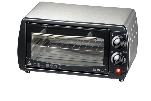
mini IR oven for my project. Its 800W and it has nice flat side for touchscreen mounting. Problem is, it will "just fit" with not much place around.

image

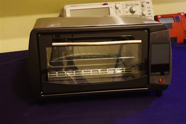
Also, all markings will be removed, and if all goes well, i have access to laser engraver for some custom markings ( in university we have laser marking machine ). Biggest problem is that i have very little room for my PWM controller, 12v power supply and my driver. I bet i have to integrate all electronics on single pcb and also send it to OHS Park for manufacturing, so not much time to spear image


Heater power control


As you might know,i will use PWM control, so i can adjust heating power , and by doing that i should get better temperature control ( low temperature "ringing" with flat temperature profile )

Idea is this. PSoC 5 will generate PWM signal by measuring temperature from sensors, and adjusting pulse width according to PID controller state. Set point will be controlled by STM32F429 via UART. At start-up, PSoC will check if driver has ULVO, if yes, displays error, since i can't run power mosfet with gate voltage below 10V. Temperature fault will not be used, since i have 100mOhms MOSFET and rms current is just 5A, that is very little of heat. ( maybe i will add more heaters to get faster heating curve, but for now original heaters will work just fine.


Simple schematic:

image


User interface

image

Hrr, is is very hard to make nice looking front panel. I have no room for any mountings, also very little room for AMOLED itself.
Plan is to use FR4 sheets, cut it with cnc, and glue them . For now it's my only option


If some one still has a question, do i really need stm32f429i, here is the answer : (still, it's only for basic functions, more pins will be used in this design )


image


Still lot of work to be done.

  • Sign in to reply
  • vitecd
    vitecd over 11 years ago

    Hello

    Can U share code and pin-outs? I like this project and also wants to try using this display.

    Thank you image

    • Cancel
    • Vote Up 0 Vote Down
    • Sign in to reply
    • More
    • Cancel
  • Kilohercas
    Kilohercas over 11 years ago in reply to jvdberg@ieee.org

    Nice to see that some one looks at my circuits and founds mistakes (well, sort of)
    Since my drawing skills are pore, i simplify circuit to fit on paper. Right now i will use two power supply's, one for FET driver, one for digital electronics. Since i am going to use power FET, i found relay unnecessary, that was just to get more control/safety. Also, i have digital insulator, so one supply ground will be connected to rectified main while digital part will be left floating, or connected to earth (case) (still don't decided yet)

    Also power fet (or maybe IGBT, i will do some calculations to see if my fet will generate less heat on same current) and rectifier will be bolted on heatsink, and heatsink fins will be outside casing, so i suspect it will have sufficient cooling. Rectifier generate on it's own very small amount of heat, so placing it on small heatsink will be more that sufficient.


    Also i can use 555 timer to trigger ( trigger delay set more than pwm period) ,so i just need to invert it, and connect to to small FET on output that turns on relay.

    • Cancel
    • Vote Up 0 Vote Down
    • Sign in to reply
    • More
    • Cancel
  • jvdberg@ieee.org
    jvdberg@ieee.org over 11 years ago

    Hi Linus, Looking at your simple schematic I found some strange things. 1e Is the transistor in the optocoupler capable of driving the coil of the relay? 2e The ground connection is connected to the negative connection of the mains rectifier.     This means the 12 Volt and 5 Volt sections of the circuit is connected to the mains voltage.     An optocoupler is not necessary; a single transistor can be used to drive the relay. A better solution would be to place the optocoupler in the PWM-signal. The control-circuit then can be isolated from the mains Voltage. Then you need an extra 12 Volt supply connected to the mains side for the driver for the IRFP32N50K Some tips: Check the temperature in the compartment where you intend to install the electronics. It might become very hot there. Thermal insulation and extra access of air might be necessary. To reduce arcing and pitting the relay-contact can be placed before the bridge rectifier. A hardware overtemperature protection can be added to switch off the heater when the control circuit fails.

    • Cancel
    • Vote Up 0 Vote Down
    • Sign in to reply
    • More
    • Cancel
  • Former Member
    Former Member over 12 years ago in reply to Kilohercas

    Last time i did PWM on mains over rectifier I nearly burned my favorite IGBT image

    But I'm sure you can test and see what happens using your load and your IGBTs.


    As for Zero Cross there are many ways to get it. In atmel datasheets it's mains connected to a digital input pin over 1meg resistor image

    I myself used one simple yet elegant optocoupled solution with small offset and one very precise with comparators in another project.

    I guess that using integrated PSoC comparator would earn you more points in this project than using external solutions image

    Try it out on your bench - depending on where will you tap into on your PSU you can use PSoCs comparator and maybe even opamp to get a very precise ZC signal.


    P.S.

    If using zero cross based control, you can configure your PWM so that it's cycle length matches 50Hz and so you would always turn transisor on during ZC but turn it off sooner or later based on duty cycle.

    What i'm trying to say here is - use trailing edge dimming equivalent:

    http://my.coolala.net/upload0713/2010/340/1291717773.jpg


    this way you will not have any noise at all - high or low frequency.


    it would look something like this:

    image


    PWM clock matching 8bit range over 10ms cycle.

    PWM configured for one-shot run activated by trigger (not sure if reset is needed after mosfet is turned off, but that's just a matter of one more virtual wire image)

    Primitive ZC implemented by comparator, comparator triggering on both, rising and falling edge.

    Add IGBT driver of your choice and double check all the stuff as this is just an idea on paper, not something already built.

    • Cancel
    • Vote Up 0 Vote Down
    • Sign in to reply
    • More
    • Cancel
  • Kilohercas
    Kilohercas over 12 years ago in reply to Former Member

    That is good idea, i will try that on my bench, and see if it works, but i have to use zero cross detector from power supply transformer to get reference for 50Hz.


    But still, backup plan is PWM control, since soon i should get parts for this project, and i will test how much RF kickback and heat i will get from my PWM controller. I know that heating is slow, but what is better, to get low frequency noise because of on/off action (flickering lights as example), or get small RF noise coupled into mains, but power draw would be very constant ? ( and LC filter will clean most of RF anyway...). and by using PWM i can mimic PFC  by adjusting dead time on zero crossing

    • Cancel
    • Vote Up 0 Vote Down
    • Sign in to reply
    • More
    • Cancel
>
element14 Community

element14 is the first online community specifically for engineers. Connect with your peers and get expert answers to your questions.

  • Members
  • Learn
  • Technologies
  • Challenges & Projects
  • Products
  • Store
  • About Us
  • Feedback & Support
  • FAQs
  • Terms of Use
  • Privacy Policy
  • Legal and Copyright Notices
  • Sitemap
  • Cookies

An Avnet Company © 2025 Premier Farnell Limited. All Rights Reserved.

Premier Farnell Ltd, registered in England and Wales (no 00876412), registered office: Farnell House, Forge Lane, Leeds LS12 2NE.

ICP 备案号 10220084.

Follow element14

  • X
  • Facebook
  • linkedin
  • YouTube