Table of contents
Abstract
In this project, I mounted a wireless camera on a slip ring driven by a stepper motor controlled by the TMC5272 controller. Motor controller and camera stream has been integrated in Octoprint to provide 360-degrees view of the object being printed
Project
The goal of this project is to built a mechanism that can provide a 360-degree view of the object being printed by my 3D printer. I own a FLSUN Q5 printer, which, with its peculiar delta configuration, drove some very specific design choices. For example, I built the spin ring to lean on three supports - one for each printer's leg. Despite this, I think the idea can be easily adapted to fit a generic cartesian printer.
But now, with no further ado, let's see how I built the Octoscope.
1. Overview
First of all, let's see the main components of the Octoscope
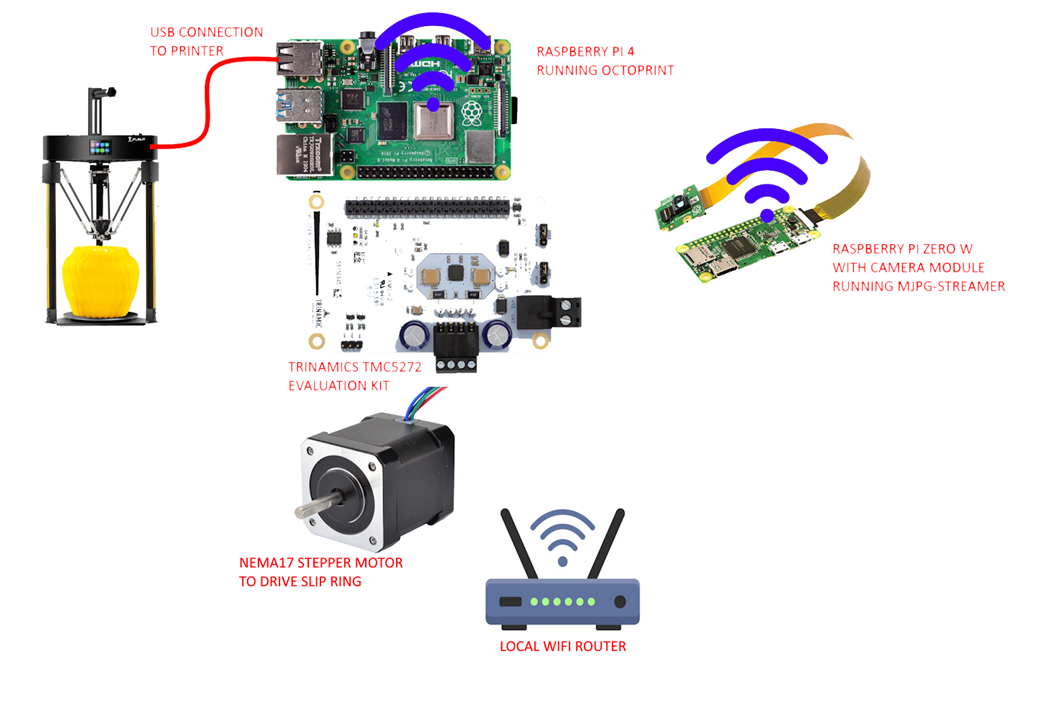
The main components here are
- A Raspberry Pi 4 SBC, which runs Octoprint and controls, through an SPI interface, the TMC5272 stepper motor controller
- The TMC5272 evaluation kit, which is controller by the Raspberry Pi 4 in velocity mode and driver the NEMA17 stepper motor
- A NEMA17 stepper motor, which drives the slip ring the wireless camera is mounted on
- A Raspberry Pi Zero W with camera module, which runs Mjpg-streamer application and stream still photos and videos to the Raspberry Pi 4
- Both the Raspberry Pi 4 and the Raspberry Pi Zero W are connected to the same local Wifi network
2. The wireless camera
First, let's see how the wireless camera has been built.
The wireless camera is built around a Raspberry Pi Zero W module with a standard Raspberry camera module. To stream photos and videos Octoprint, I installed mjpg-streamer application, but let's see the process step by step.
Step 1: Prepare the Raspberry Pi Zero W
-
Download DietPi Image:
- Visit the DietPi website.
- Navigate to the "Download" section and select the appropriate image for Raspberry Pi
-
Flash the DietPi Image to MicroSD Card:
- Download and install Raspberry Pi Imager. Using Raspberry Pi imager simplify the subsequent steps where we configure the Wifi SSID and password and enable SSH access
- Insert the microSD card into your computer.
- Use the tool to flash the downloaded DietPi image onto the microSD card.
-
Configure Wi-Fi (Optional):
- Follow the instructions in this Getting started guide to configured Wifi credentials and enable SSH access
- Insert and Boot:
- Insert the microSD card into your Raspberry Pi Zero W.
- Power on the Raspberry Pi.
Step 2: Enable the camera module
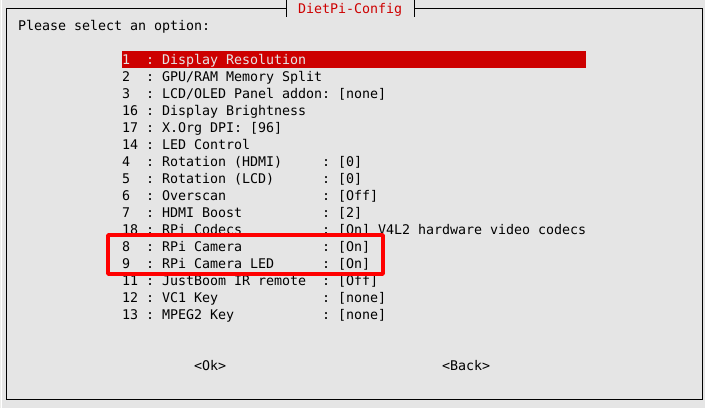
The official Raspberry Pi camera module can be enabled via dietpi-config > Display Options > RPi Camera to show [On].
Additionally, the behaviour of the cameras LED can be set in the same dialog via RPi Camera LED.
Remark: After changing the camera activation you need to reboot and/or sometimes power cycle the SBC incl. camera.
Step 3: Configure MJPEG-Streamer
You can now configure MJPEG-Streamer. Run the following command:
This will open the DietPi software management tool.
- Scroll through the available software or use the search function (press
/and typemjpeg). - Locate MJPEG-Streamer and select it by pressing the space bar. A
[X]will appear next to it. - After selecting MJPEG-Streamer, press Enter to proceed to the next step.
- DietPi-Software will prompt you to confirm the installation. Confirm and begin the installation process. DietPi will automatically handle the download, compilation, and installation of MJPEG-Streamer.
- After the build and installation process completes, edit file /etc/systemd/system/mjpg-streamer.service and replace mjpeg_streamer's commandline parameter "'input_raspicam.so" with "input_uvc.so"
- Restart the board to apply changes
Step 4: Print the case
Download, slice and print the three files in the STL/WirelessCamera folder of the github repository
- Pi_Zero_Case_Cover_Vented_2.STL
- Pi_Zero_Case_Arm_Mount.STL
- Pi_Zero_Arm.STL
Using some 1.5 mm screw, house the Raspberry Pi Zero W module and the camera module in the case and place the cover in place
3. Controlling the stepper motor from Python
To control the stepper motor, I developed the Python scripts you can find in the github repository in the folder scripts/tmc5272. Namely, the script to be invoked is move.py. This script accepts two parameters on the command line
- the first parameter is either "cw" or "ccw", to select the direction of the movement
- the second parameter is the velocity, which is represented by a value from 0 to 255. The value provided is multiplied by 256, to get a value of steps per unit of time that can range from 0 to 65280
Here is the code that configures the registers of the TMC5272 to set the velocity and acceleration
   direction = sys.argv[1]
    speed = int(sys.argv[2]) * 256

    print("Setting IHOLD_IRUN...")
    write_register(0x12, 0x04011F0A)
    print("Setting TPOWERDOWN...")
    write_register(0x13, 0x0000000A)
    print("Setting DRV_CONF...")
    write_register(0x05, 0x0000000E)
    print("Setting GLOBAL_SCALER...")
    write_register(0x06, 0x0000B0B0)

    print("Setting RAMPMODE...")
    write_register(0x07, 0x00000001)

    print("Setting CHOPCONF...")
    write_register(0x38, 0x10410153)

    gconf = 0x00020002
    if (direction == 'ccw'):
        gconf |= 0x00040004

    print(f"Setting GCONF to {gconf:08X}...")
    write_register(0x00, gconf)

    print("Setting AMAX and DMAX...")
    write_register(0x20, 0x00000631)
    write_register(0x22, 0x00000631)
    print(f"Setting VMAX to {speed} {speed:08X}...")
    write_register(0x21, speed)
The move.py script is invoked by three scripts (move_stop.sh, move_cw.sh, move_ccw.sh) which are located in the folder scripts of the github repository. These scripts will, in turn, be invoked by the Octoprint's GCODE System commands plugin (see next section for details)
The connections between the Raspberry Pi and the TMC5272 evaluation board are as follow (more details in this post)
- MOSI: Raspberry Pi Pin 19 (GPIO10) → TMC5272 SPI1_MOSI (Pin 32)
- MISO: Raspberry Pi Pin 21 (GPIO9) → TMC5272 SPI1_MISO (Pin 33)
- SCLK: Raspberry Pi Pin 23 (GPIO11) → TMC5272 SPI1_SCK (Pin 31)
- CS_0: Raspberry Pi Pin 24 (GPIO8) → TMC5272 SPI1_CSN (Pin 30)
- Power: Raspberry Pi Pin 2 (5V) → TMC5272 +5V_USB (Pin 5)
- Ground: Raspberry Pi Pin 6 (GND) → TMC5272 GND (Pin 3)
4. Octoprint integration
Let's now see how to install Octoprint on the Raspberry Pi 4 board and how to integrate the new commands to control the stepper motor
Step 1: Install Octoprint
Installing OctoPi on a Raspberry Pi board is quite straightforward: you can burn the image on an SD card using the Raspberry Pi Imager. You then have to choose the OctoPi image under “Choose OS”, by selecting “Other Specific Purpose OS” > “3D printing” > “OctoPi” and then the “stable” version.
Before proceeding, it's a good idea to enable SSH server and configure Wifi SSID and password. See the Raspberry's Getting started guide for more details.
When the image has been written, you can insert the SD card in the Raspberry Pi's SD slot and power up the system. You should be able to access OctoPi's web interface at the URL https://<Raspberry Pi's IP>/. You can login using the username "admin" and the default password "admin".
Step 2: Install GCODE System Commands plugin
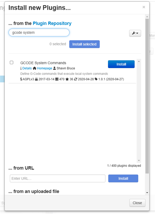
This plugin is required to handle to GCODE commands I will associate to the new command buttons I will add to the "Controls" tab of the Octoprint interface. To install the plugin, click on the wrench icon in the toolbar, then click, in the left pane, the Plugin manager item.
Start typing the plugin name in the search field, then, when you can locate the correct plugin in the search results, click "Install"
Let's now configure the plugin itself. Further down in the settings page, you can see a link to open the plugin custom settings. This link should bring you to a page like this
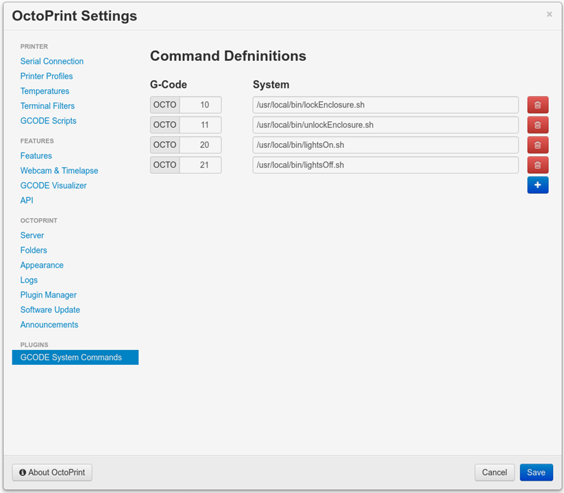
Here you can define new GCODE commands, each one uniquely identified by a fixed prefix ("OCTO") and a user-defined number). For each GCODE command, you can enter the system command or script to execute. In this case, I will create three new GCode commands
- OCTO900: calls /home/pi/move_stop.sh
- OCTO901: calls /home/pi/move_cw.sh
- OCTO902: calls /home/pi/move_ccw.sh
Scripts can access the command line parameters and other useful information by means of three environment variables
- OCTOPRINT_GCODESYSTEMCOMMAND_ID: this is the GCode command (for example OCTO900)
- OCTOPRINT_GCODESYSTEMCOMMAND_ARGS: this variables store the command arguments. For example, the OCTO901 and OCTO902 commands will be called with 1 parameter, as per config.yaml (more details about this file below)
command: OCTO902 %(speed)s
In this case, OCTOPRINT_GCODESYSTEMCOMMAND_ARGS will contain the value of the speed parameter, which can be changed through the slider control
- OCTOPRINT_GCODESYSTEMCOMMAND_LINE: stores the command (for example, /home/pi/move_cw.sh)
Step 3: Configure Octoprint's camera URLs
Remain in the Octoprint settings page, and locate the "Webcam classic" plugin custom settings. In the custom settings page, enter the following URLs
- Streaming URL: http://<OctoPi_IP>/stream
- Snapshot URL: http://<PiZeroW_IP>:8082/?action=snapshot
- Path to FFMPEG: This is required for features like time-lapse rendering. The typical path is: /usr/bin/ffmpeg
Step 4: Configure HAProxy to handle camera stream
In the above URLs, you may have noted that the Streaming URL points to the IP of the Raspberry Pi running the Octopi software, not to the Raspberry Pi Zero W with the MJPEG Streamer. This is because modern browsers tend to block mixed contents (served via HTTPS and HTTP).To make the stream work, I changed the configuration of the haproxy. HAProxy (High Availability Proxy) is an open-source software solution that provides load balancing, reverse proxying, and high availability for TCP and HTTP-based applications. I edited file /etc/haproxy/haproxy.cfg and added a new backend in the frontend public section
frontend public
bind :::80 v4v6
bind :::443 v4v6 ssl crt /etc/ssl/snakeoil.pem
option forwardfor except 127.0.0.1
use_backend webcam if { path_beg /webcam/ }
use_backend webcam_hls if { path_beg /hls/ }
use_backend webcam_hls if { path_beg /jpeg/ }
use_backend webcam_stream if { path_beg /stream }
default_backend octoprint
The new backend has been added at the end of the same file. I simply replaced the /stream URL with the URL requested by MJPEG streamer, and added the IP address of the Raspberry Pi Zero W that runs MJPEG streamer application (192.168.118.100)
backend webcam_stream
http-request replace-path /stream /?action=stream
server webcam_stream1 192.168.118.100:8082
Step 5: Copy files and Python scripts
Copy files from github repository to the Raspberry Pi folder according to the following table
github file Raspberry Pi folder
scripts/tmc5272/move.py /home/pi/tmc5272
scripts/move_stop.sh /home/pi
scripts/move_cw.sh /home/pi
scripts/move_ccw.sh /home/pi
scripts/config.yaml /home/pi/.octoprint
Ensure that scripts files (move_stop.sh, move_cw.sh, move_ccw.sh) have execute permission. To stay on the safe side, run the following command
cd /home/pi
sudo chmod +x *.sh
5. The slip ring
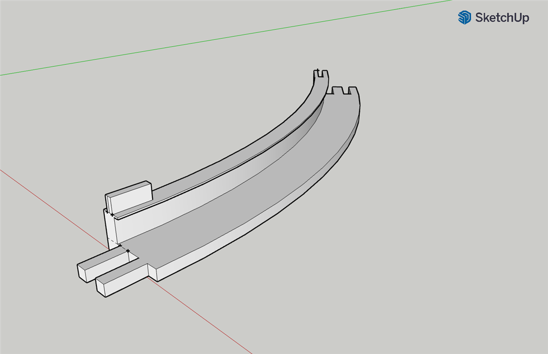
From a mechanical point of view, the slip ring is made of 16 different identical parts. The part to print is located in STL/SlipRing/Wheel2.STL. Hot-glue 8 sectors to make 2 rings, then hot-glue one ring on the top of the other. Apply a copper tape in the two grooves
The slip ring moves on three stands: two are standard stands, whereas the third one sports an housing for the stepper motor. The parts to print are
- STL/SlipRing/Bracket.STL
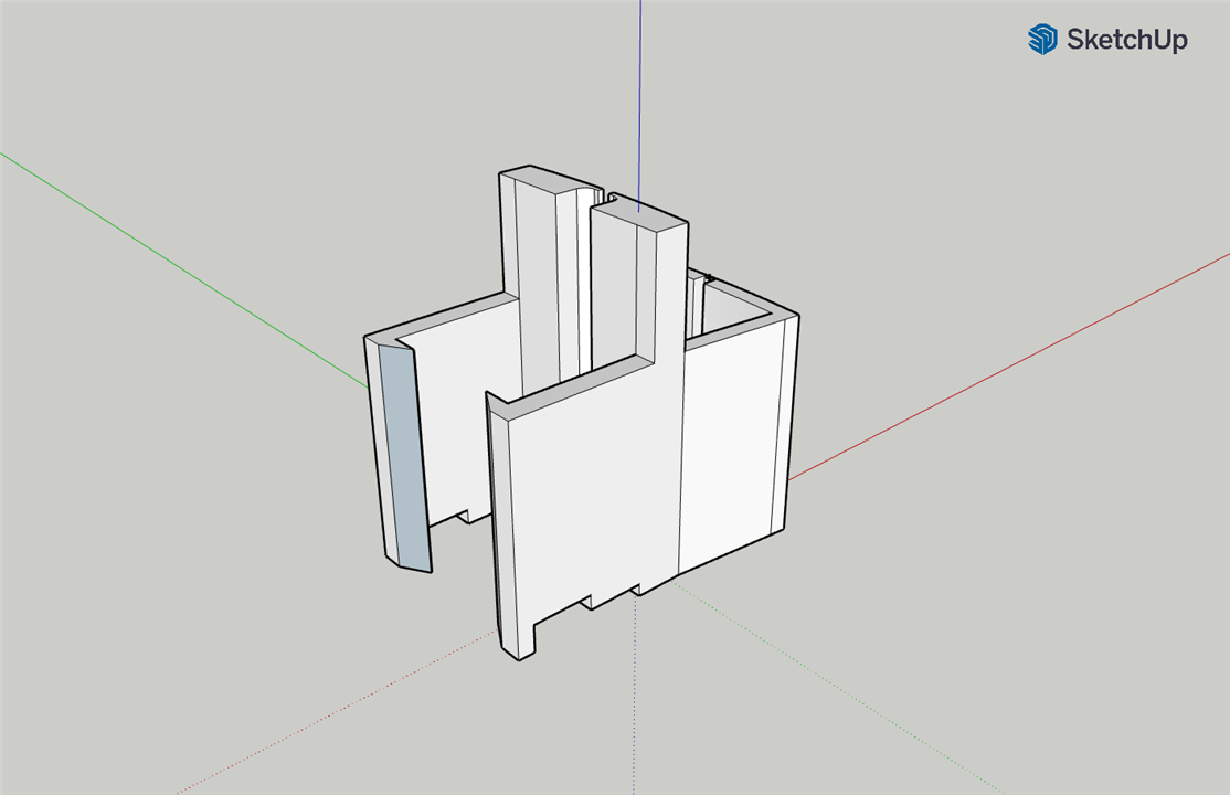
- STL/SlipRing/Bracket_Stepper.STL

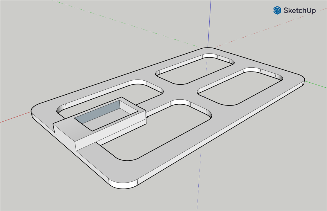
Finally print STL/SlipRing/Base.STL. This is the support where both the Raspberry Pi 4 and the TMC5272 Evaluation kit boards will be mounted. Base.STL must be glued to the part named Bracket_Stepper.STL
6. Demo video
References
Trinamics TMC5272 product page
Octoprint config.yaml specification
Octoprint's GCODE system commands plugin
___ FORUM POSTS ___
Connecting the TMC5272 Evaluation board to raspberry Pi
Configuring the wireless camera
Integrating motor control in Octoprint


Top Comments