1# Roadtest to TMC5272-EVAL-KIT and TRINAMIC stepper motor
Table of Contents
1 Introduction
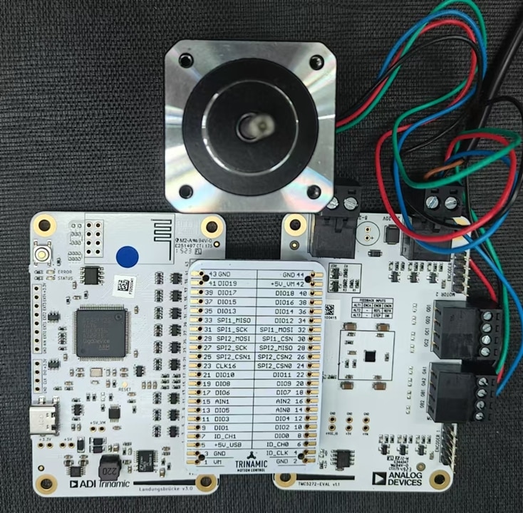
The TMC5272 is a Step/Dir Driver for Two-Phase Bipolar Stepper Motors up to 0.8 A (RMS) (1.12 A (PEAK)). TMC5272-EVAL-KIT and Landungsbruecke with with bridge Board can run with TMCL-IDE to rest the performance and function of the TMC5272. One RINAMIC Stepper Motor, Single Shaft, Hybrid, 42 mm, Bipolar, 1.8 °, 27 N-cm, 1 A is used as stepper motor in this road test.
Refer to TMC5272-EVAL Evaluation Board | Analog Devices and LANDUNGSBRUECKE Evaluation Board | Analog Devices for more details.

2 TMC5272-EVAL-KIT and TRINAMIC stepper motor
The TMC5272-EVAL allows evaluation of the TMC5272 in combination with the ADI TRINAMIC evaluation board system, or as a stand-alone board. It uses the standard schematic and offers several options in order to test different modes of operation. The TMC5272 is a Step/Dir Driver for Two-Phase Bipolar Stepper Motors up to 0.8 A RMS (1.5 A peak). The board is full functions with high performance and easy control. With features as,
CoolStep
Passive Braking
Short Detection
Slope Control
StallGuard2
MicroPlyer
DcStep
Position Mode
Velocity Mode
Dual Encoder
2x 2-phase stepper motor up to 0.8 A (RMS) coil current (1.12 A (PEAK))
Supply Voltage 2.1 to 20 V DC
SPI and Single Wire UART
Encoder Interface with alt. functions
1 to 256 microsteps
StealthChop2 silent PWM mode
StallGuard4 sensorless motor load detection
TriCoder Sensorless Standstill Steploss Detection and Full Step Encoder
There functions are good for smooth and precise control for high end tasks in industrial, medical and consumer products.
And this the parameter and function for this stepper motor.
3 TMCL-IDE
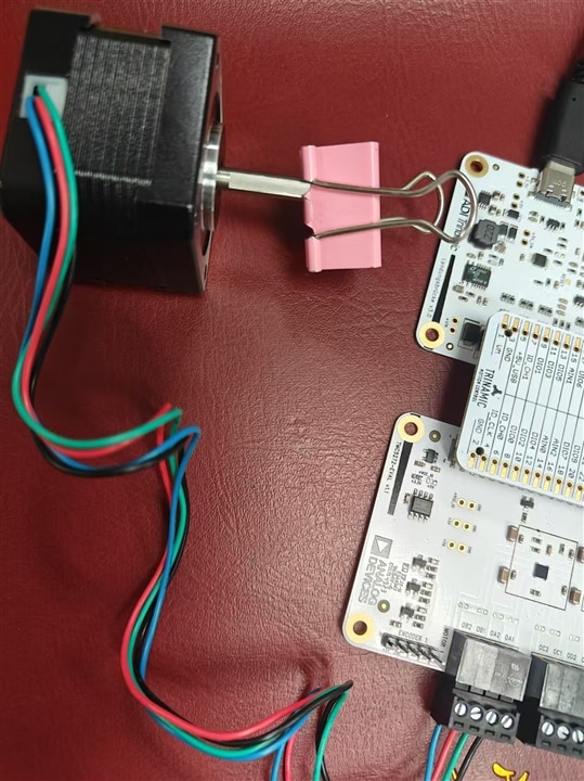
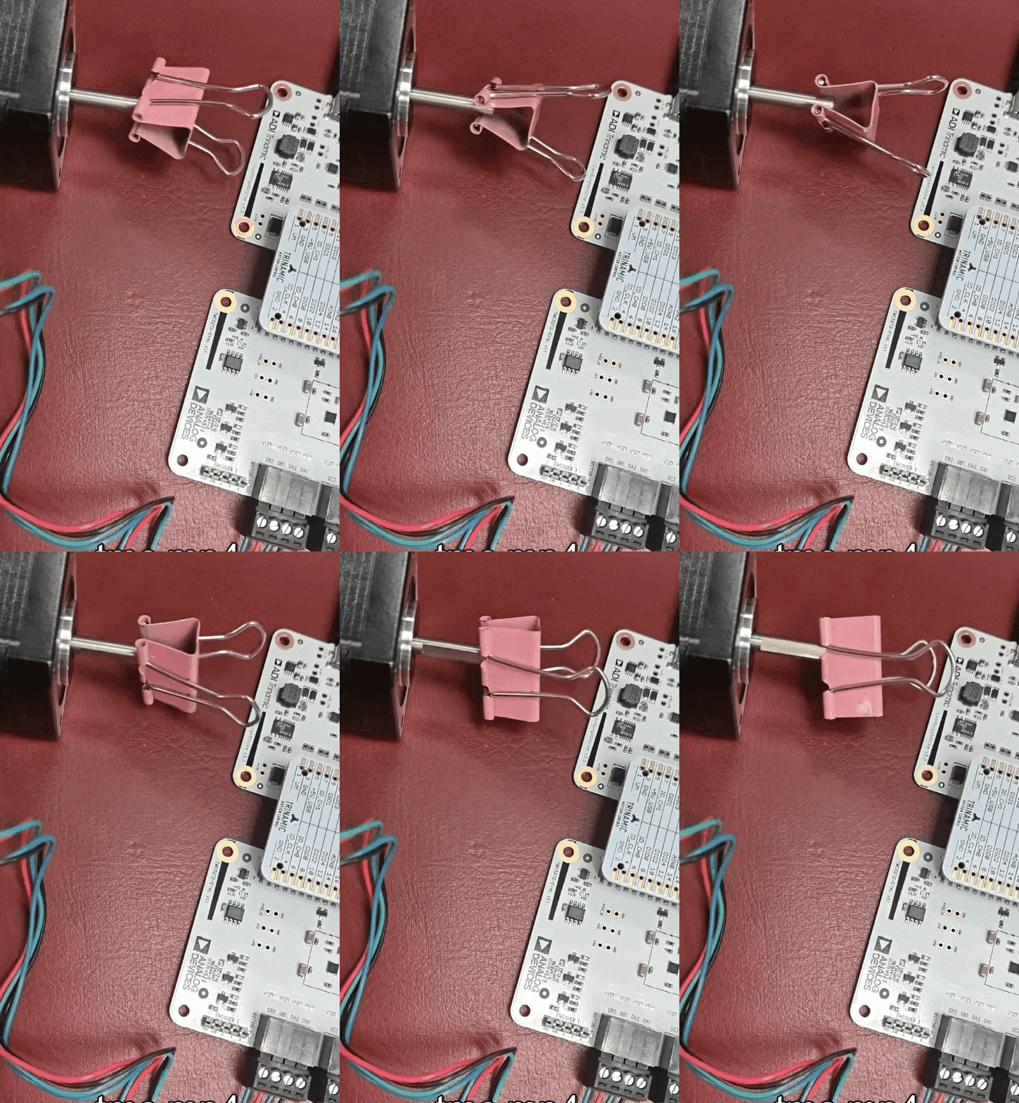
TMCL-IDE is best used in this road test and help understanding the how the above features works. The hardware is configurated below, one pink clipper on the shaft can show how the stepper motor runs.

This the short video for the stepper motor in velocity mode,

Start the TMCL-IDE,
if the board is not automatic recognized, manually select it. or it is in direct mode only
The board connect the TMIC-IDE in serial port, all function is opened for roadtest,
Here is settings, the drive board is unknown, so manually selected as well.
update the firmware for driver board first,
wait until if completed successfully.
All the function can be control and traced in registers,
Functions in GUI for easy control
IN direct mode, the registers are read or write directly for fast control
Now connect and plug 12V DC power, the ADC readings show the input voltages and some info.
adjust the reference current setting to make the calibration button green. In this case the settings is 0.1A
The feedback current sensing shows 0.1A as well,
For advance control in coolsteps and stallGuard
Square PWM waveform is normally used, and it can be configurated in sinus mode as this part shows,
The stepper motor can be controlled in position mode or velocity mode, 256 steps per round and the position is defined in steps
Here is the control GUI
this is velocity mode GUI
The velocity can be controlled as smooth as it can be , change the number or simple pull the virtual button, feel how the TMC5272 drive the stepper motors.
4 Drive the stepper motor and Next to do
This roadtest is easy and pleasant, try the TMCL-IDE with reading the reference manual. High performance of TMC5272 can easily be found out. My proposal is drive the rover with stepper motor, in fact , it can be more fit for precise control in millimeters or even smaller. Next step shall be build the rover and setting the range detect sensors.
