element14 Community
element14 Community
    Register Log In
  • Site
  • Search
  • Log In Register
  • About Us
  • Community Hub
    Community Hub
    • What's New on element14
    • Feedback and Support
    • Benefits of Membership
    • Personal Blogs
    • Members Area
    • Achievement Levels
  • Learn
    Learn
    • Ask an Expert
    • eBooks
    • element14 presents
    • Learning Center
    • Tech Spotlight
    • STEM Academy
    • Webinars, Training and Events
    • Learning Groups
  • Technologies
    Technologies
    • 3D Printing
    • FPGA
    • Industrial Automation
    • Internet of Things
    • Power & Energy
    • Sensors
    • Technology Groups
  • Challenges & Projects
    Challenges & Projects
    • Design Challenges
    • element14 presents Projects
    • Project14
    • Arduino Projects
    • Raspberry Pi Projects
    • Project Groups
  • Products
    Products
    • Arduino
    • Avnet Boards Community
    • Dev Tools
    • Manufacturers
    • Multicomp Pro
    • Product Groups
    • Raspberry Pi
    • RoadTests & Reviews
  • Store
    Store
    • Visit Your Store
    • Choose another store...
      • Europe
      •  Austria (German)
      •  Belgium (Dutch, French)
      •  Bulgaria (Bulgarian)
      •  Czech Republic (Czech)
      •  Denmark (Danish)
      •  Estonia (Estonian)
      •  Finland (Finnish)
      •  France (French)
      •  Germany (German)
      •  Hungary (Hungarian)
      •  Ireland
      •  Israel
      •  Italy (Italian)
      •  Latvia (Latvian)
      •  
      •  Lithuania (Lithuanian)
      •  Netherlands (Dutch)
      •  Norway (Norwegian)
      •  Poland (Polish)
      •  Portugal (Portuguese)
      •  Romania (Romanian)
      •  Russia (Russian)
      •  Slovakia (Slovak)
      •  Slovenia (Slovenian)
      •  Spain (Spanish)
      •  Sweden (Swedish)
      •  Switzerland(German, French)
      •  Turkey (Turkish)
      •  United Kingdom
      • Asia Pacific
      •  Australia
      •  China
      •  Hong Kong
      •  India
      •  Korea (Korean)
      •  Malaysia
      •  New Zealand
      •  Philippines
      •  Singapore
      •  Taiwan
      •  Thailand (Thai)
      • Americas
      •  Brazil (Portuguese)
      •  Canada
      •  Mexico (Spanish)
      •  United States
      Can't find the country/region you're looking for? Visit our export site or find a local distributor.
  • Translate
  • Profile
  • Settings
Start a Movement Challenge
  • Challenges & Projects
  • Design Challenges
  • Start a Movement Challenge
  • More
  • Cancel
Start a Movement Challenge
Forum AVR Part 5 – Connecting Variac and Stepper
  • Blog
  • Forum
  • Projects
  • DC
  • Leaderboard
  • Files
  • Members
  • More
  • Cancel
  • New
Join Start a Movement Challenge to participate - click to join for free!
Actions
  • Share
  • More
  • Cancel
Forum Thread Details
  • Replies 10 replies
  • Subscribers 46 subscribers
  • Views 813 views
  • Users 0 members are here
  • design challenge
  • avr
  • start a movement
  • tmc5272 evaluation kit
Related

AVR Part 5 – Connecting Variac and Stepper

Gough Lui
Gough Lui 8 months ago

In this chapter, I’ll be looking at my last-ditch attempt to progress my “Make a Movement” design challenge in spite of my medical conditions. As I cannot walk, I’ve had to literally crawl around to make this happen. After all, the finish line is getting closer by the day.

The Variac

The unit in question is an old Yamabishi Electric Variac from Japan. This was a purchase from a ham-fest many years back, so it’s nothing particularly modern, so safety isn’t exactly high on the list of features.

image

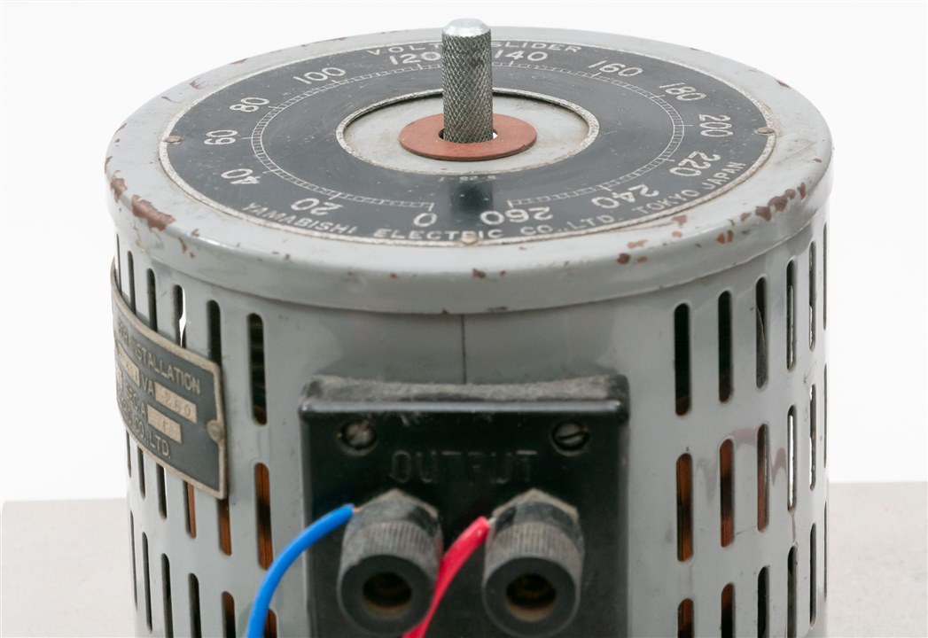
Nevertheless, after removing the grub screw and removing the knob, I found the centre shaft to be 8mm in diameter with knurling. The shaft protrudes 18.5mm from the surface of the Variac. There is no flat-section on the shaft, being entirely round. The top surface of the Variac didn’t have any mounting holes, so there is nowhere to directly anchor the stepper motor.

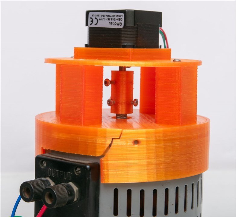
As a result, I decided that I needed to design a “hat” to fit over the top 117mm diameter surface of the unit and hold itself in place with some screws pushing on the metal surface of the casing and using the rectangular surface near the terminals. That way, it would be like a “hat” sitting on top of the Variac.

In order to do this, I drew up a quick design in TinkerCAD to accommodate this, but also to adapt this “hat” up to a new mounting surface which would be just the right height to keep the stepper and Variac shafts centred and not quite touching one-another.

image

Stepper Motor

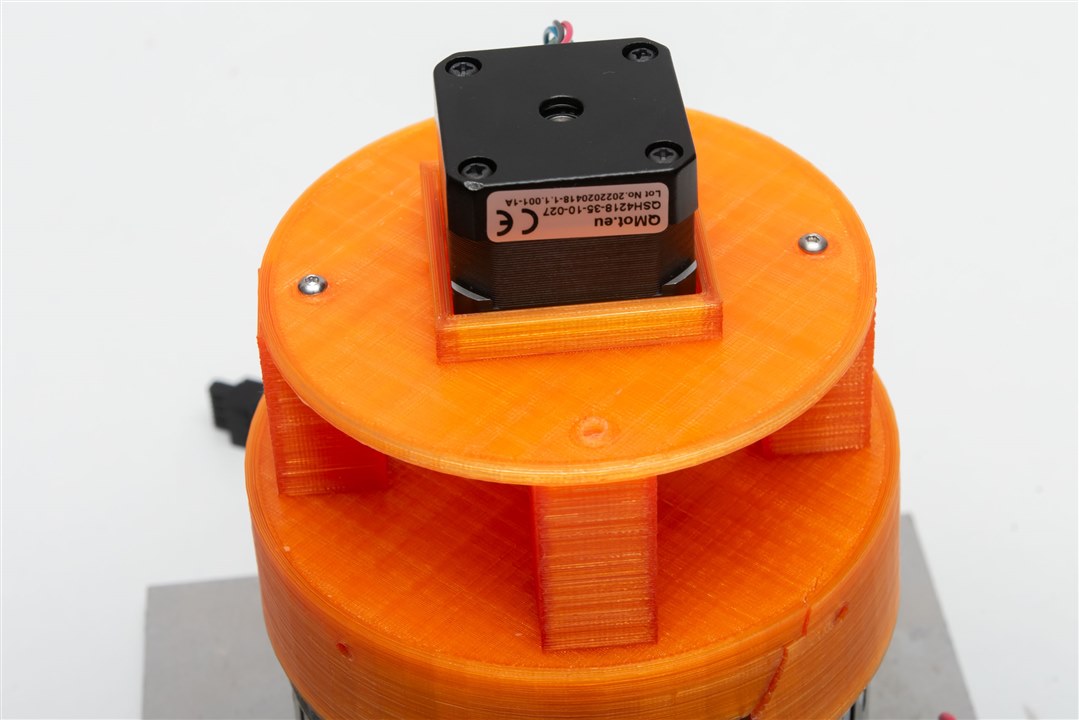
The stepper motor is a NEMA17 style motor. As a result, it has a square form factor with M3 mounting holes spaced 31mm apart. They appear to be tapped to a depth about 4-5mm. The motor body itself measures 42mm and is 33.5mm deep. The shaft measured 5mm diameter with a D-cut profile with 20mm of height. The shaft raises 24mm from the body of the motor, including the 2mm raised portion of 22mm diameter.

image

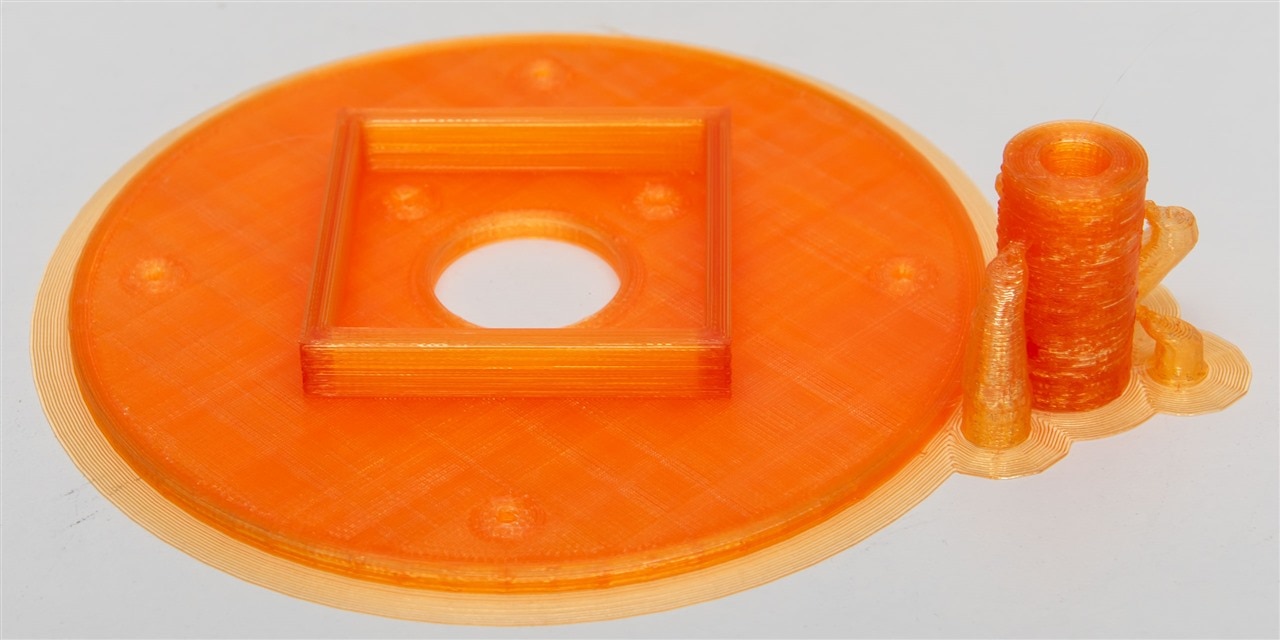
To adapt this, I have a flat, round plate of 3mm thickness with the mounting holes for the NEMA17 style motor and a barrier surrounding the motor itself to add additional strength. I felt this was necessary to ensure that any over-stress doesn’t destroy the adapter.

Coupling

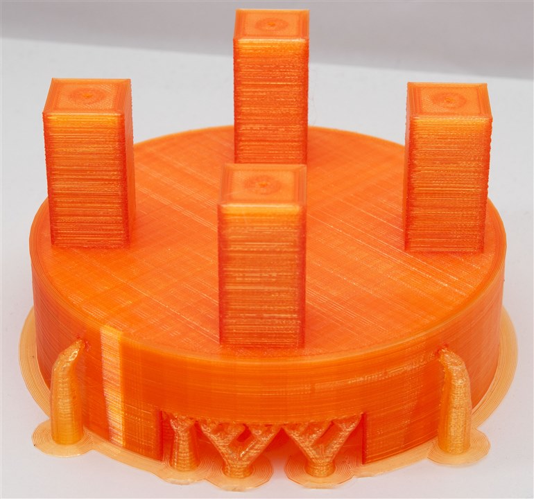
Coupling two round shafts together is a bit of complex business, as they might not be perfectly aligned in the centre. Nevertheless, not having any access to mechanical hardware like belts and pulleys or spider couplings, I decided simply to 3D print a “tube” with the provision for screws to add additional clamping force. It’s not high-tech and it won’t work for high torque, but perhaps that’s a “feature” and not a bug, in case of any unexpected accidents.

image

3D Printing and Fitting

image

After designing it, I decided to employ my 3D printer to manufacture these parts and see if it would work. My printer is a bit old and the belts are a bit sloppy, given the short time remaining, I’ve pushed the speed to the absolute maximum.

image

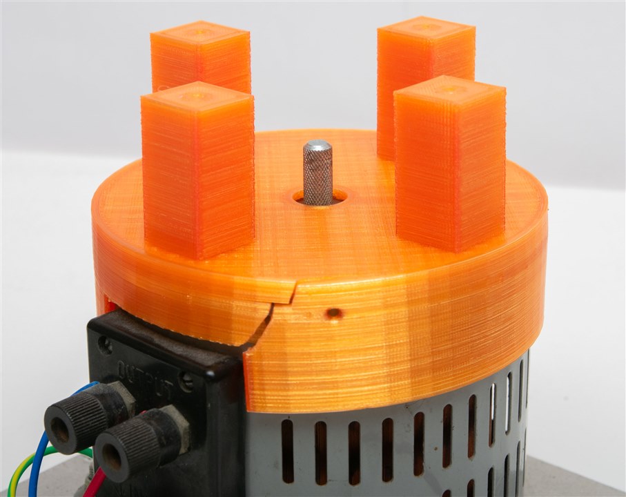
The “Variac hat” was supposed to be a tight fit, but this was too tight. After tapping it a few times with a hammer, it split along the side. It’s still tight on the unit, although this does mean that there might be a bit of off-axis alignment when fitting the stepper.

image

The stepper plate and coupler were printed as a second job due to bed space limitations.

image image

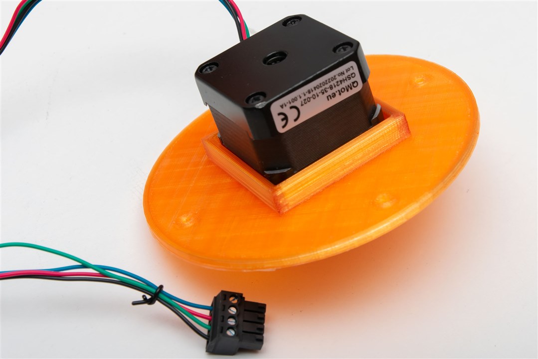
The motor fits well within the plate.

image

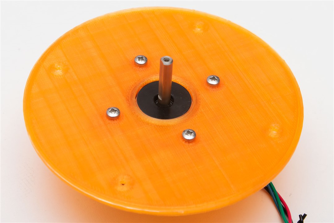
The coupling needed to be cleaned out with a drill bit to get to the right diameter. Unfortunately, once the coupling had both shafts inserted, it was evident that the two axes were not quite aligned, resulting in difficulties getting the top plate installed.

image

As a result, just two screws were used to secure the top plate to the hat, alongside some reaming of the screw holes to provide a bit more adjustment room. The coupling was unfortunately not very tight on the Variac side, leading to the potential for slip. Using plastic and having machine screws cut threads into it doesn’t result in much strength. This might protect the Variac from over-torque damage, but it does mean that step-to-ratio correspondence may not be maintained. The design also doesn't have a defined way to detect the end stops (e.g. by limit switches) and would instead have to either naively bump into an end stop repeatedly to guarantee a position or use StallGuard.

Attempting to run the board today, it seemed that the Landungsbrucke didn’t detect the driver. Even pressing scan didn’t work, but manually selecting it seemed to restore it to operation.

image

Not sure what went wrong – it was automatically detected previously. Perhaps I have a bad/broken connection somewhere.

You don't have permission to edit metadata of this video.
Edit media
x
image
Upload Preview
image

Testing with the board shows the motor has sufficient torque to overcome the slightly stiff shaft of the Variac. The coupling does result in some motor resonances being coupled into the wiper brush assembly, which is probably not good for lifetime, but turning on StealthChop seemed to reduce some of them.

Conclusion

Well, it seems I made some rookie mistakes by not accounting for the tolerances in the top of the Variac and the 3D printer, resulting in an adapter that was just too tight, resulting in it cracking as soon as it was fitted. This could be remedied with a slight adjustment to the 3D model and a re-print. The slightly off-center part of the spindle on the Variac was not expected, but made the top plate mounting difficult. Testing seemed to show the motor to be capable enough of driving the wiper, but there is a potential for slipping with the current plastic coupling and the potential for resonances to be coupled into the wiper which might accelerate its wear.

Unfortunately, I hadn’t had any time to work on the integration of the driver control with a third-party microcontroller platform. I’m intending to use the Wiznet W5500-EVB-Pico based on the RP2040 as I’ve used with other creations, but the software will need to be ported, driver connected and tested. This time, I’m really out of time … so this will be the end of the series. At least, I’m somewhat closer to my goal, even if I did not reach it in the end.

  • Sign in to reply
  • Cancel

Top Replies

  • michaelkellett
    michaelkellett 8 months ago +4
    Heroic effort ! Most of us just have to overcome laziness and inertia. Good to read about it - I've often wanted an excuse to buy a motorised 3 phase Variac but nothing workwise has ever come up which…
  • dougw
    dougw 8 months ago +1
    A valiant effort. Good job getting as far as you did. I can relate to trying to complete a project without being able to walk. On my printer, when going fast I would need to oversize the cylinder by…
  • kmikemoo
    kmikemoo 8 months ago +1
    Gough Lui I still like it. You've demonstrated that the concept and device will do what you wanted it to do. I was wondering if the stepper could overcome the resistance to movement that all Variacs have…
Parents
  • michaelkellett
    michaelkellett 8 months ago

    Heroic effort !

    Most of us just have to overcome laziness and inertia.

    Good to read about it  - I've often wanted an excuse to buy a motorised 3 phase Variac but nothing workwise has ever come up which can't be solved by the hand cranked second hand one I already have. It has a good history, having belonged to the guy who designed a pickup arm and cartridge for the leak HiFi company in 1950s.

    I hope you recover soon.

    Here's a picture of a 60A 3 phase job to cheer you up !

    image

    MK

    • Cancel
    • Vote Up +4 Vote Down
    • Sign in to reply
    • Cancel
  • Gough Lui
    Gough Lui 8 months ago in reply to michaelkellett

    I knew those things existed and I've been secretly jealous of the ones I've seen on photonicinduction's channel. Heavy duty beasts - I've heard some being used on industrial processes or as lighting dimmers for old stage shows back in the incandescent days. But alas, Variacs aren't cheap nowadays and motorised ones especially. This was an attempt to make-do with what I had on hand ... I think conceptually, it's all fine. The execution is still lacking though, but can yet be refined. Nevertheless, I'm going to publish the "wrap-up" project posting for this design challenge with under 24h to go. Perhaps this is something I can revisit when I end up having a bit more energy and time.

    Thanks everyone for your support and for following along. It really means a lot to me. As usual, please show your support to all the other, arguably more worthy, competitors as well Slight smile.

    - Gough

    • Cancel
    • Vote Up 0 Vote Down
    • Sign in to reply
    • Cancel
Reply
  • Gough Lui
    Gough Lui 8 months ago in reply to michaelkellett

    I knew those things existed and I've been secretly jealous of the ones I've seen on photonicinduction's channel. Heavy duty beasts - I've heard some being used on industrial processes or as lighting dimmers for old stage shows back in the incandescent days. But alas, Variacs aren't cheap nowadays and motorised ones especially. This was an attempt to make-do with what I had on hand ... I think conceptually, it's all fine. The execution is still lacking though, but can yet be refined. Nevertheless, I'm going to publish the "wrap-up" project posting for this design challenge with under 24h to go. Perhaps this is something I can revisit when I end up having a bit more energy and time.

    Thanks everyone for your support and for following along. It really means a lot to me. As usual, please show your support to all the other, arguably more worthy, competitors as well Slight smile.

    - Gough

    • Cancel
    • Vote Up 0 Vote Down
    • Sign in to reply
    • Cancel
Children
No Data
element14 Community

element14 is the first online community specifically for engineers. Connect with your peers and get expert answers to your questions.

  • Members
  • Learn
  • Technologies
  • Challenges & Projects
  • Products
  • Store
  • About Us
  • Feedback & Support
  • FAQs
  • Terms of Use
  • Privacy Policy
  • Legal and Copyright Notices
  • Sitemap
  • Cookies

An Avnet Company © 2025 Premier Farnell Limited. All Rights Reserved.

Premier Farnell Ltd, registered in England and Wales (no 00876412), registered office: Farnell House, Forge Lane, Leeds LS12 2NE.

ICP 备案号 10220084.

Follow element14

  • X
  • Facebook
  • linkedin
  • YouTube