element14 Community
element14 Community
    Register Log In
  • Site
  • Search
  • Log In Register
  • About Us
  • Community Hub
    Community Hub
    • What's New on element14
    • Feedback and Support
    • Benefits of Membership
    • Personal Blogs
    • Members Area
    • Achievement Levels
  • Learn
    Learn
    • Ask an Expert
    • eBooks
    • element14 presents
    • Learning Center
    • Tech Spotlight
    • STEM Academy
    • Webinars, Training and Events
    • Learning Groups
  • Technologies
    Technologies
    • 3D Printing
    • FPGA
    • Industrial Automation
    • Internet of Things
    • Power & Energy
    • Sensors
    • Technology Groups
  • Challenges & Projects
    Challenges & Projects
    • Design Challenges
    • element14 presents Projects
    • Project14
    • Arduino Projects
    • Raspberry Pi Projects
    • Project Groups
  • Products
    Products
    • Arduino
    • Avnet Boards Community
    • Dev Tools
    • Manufacturers
    • Multicomp Pro
    • Product Groups
    • Raspberry Pi
    • RoadTests & Reviews
  • Store
    Store
    • Visit Your Store
    • Choose another store...
      • Europe
      •  Austria (German)
      •  Belgium (Dutch, French)
      •  Bulgaria (Bulgarian)
      •  Czech Republic (Czech)
      •  Denmark (Danish)
      •  Estonia (Estonian)
      •  Finland (Finnish)
      •  France (French)
      •  Germany (German)
      •  Hungary (Hungarian)
      •  Ireland
      •  Israel
      •  Italy (Italian)
      •  Latvia (Latvian)
      •  
      •  Lithuania (Lithuanian)
      •  Netherlands (Dutch)
      •  Norway (Norwegian)
      •  Poland (Polish)
      •  Portugal (Portuguese)
      •  Romania (Romanian)
      •  Russia (Russian)
      •  Slovakia (Slovak)
      •  Slovenia (Slovenian)
      •  Spain (Spanish)
      •  Sweden (Swedish)
      •  Switzerland(German, French)
      •  Turkey (Turkish)
      •  United Kingdom
      • Asia Pacific
      •  Australia
      •  China
      •  Hong Kong
      •  India
      •  Korea (Korean)
      •  Malaysia
      •  New Zealand
      •  Philippines
      •  Singapore
      •  Taiwan
      •  Thailand (Thai)
      • Americas
      •  Brazil (Portuguese)
      •  Canada
      •  Mexico (Spanish)
      •  United States
      Can't find the country/region you're looking for? Visit our export site or find a local distributor.
  • Translate
  • Profile
  • Settings
Summer of FPGA
  • Challenges & Projects
  • Design Challenges
  • Summer of FPGA
  • More
  • Cancel
Summer of FPGA
Blog Analog signal processing on FPGA #2 - Integration of the MicroBlaze IP core into the FPGA
  • Blog
  • Forum
  • Documents
  • Files
  • Mentions
  • Sub-Groups
  • Tags
  • More
  • Cancel
  • New
  • Share
  • More
  • Cancel
Group Actions
  • Group RSS
  • More
  • Cancel
Engagement
  • Author Author: maxpowerr
  • Date Created: 28 Jan 2022 2:32 PM Date Created
  • Views 781 views
  • Likes 3 likes
  • Comments 0 comments
  • spartan 7
  • xilinx
  • fpga
  • vivado
  • summer of fpga
  • microblaze
  • cmod s7
Related
Recommended

Analog signal processing on FPGA #2 - Integration of the MicroBlaze IP core into the FPGA

maxpowerr
maxpowerr
28 Jan 2022

In this part, I will describe how I integrated the MicroBlaze IP core into the FPGA.

I have Vivado 2019.1 installed. There is a good description of how to install Vivado and Board File here: https://digilent.com/reference/programmable-logic/ guides/installing-vivado-and-sdk

How to launch Vivado, create a new project, add a constraint file - Xilinx Design Constraint (XDC) and get acquainted with a brief description of the interface here: https://digilent.com/reference/vivado/getting_started/2018.2

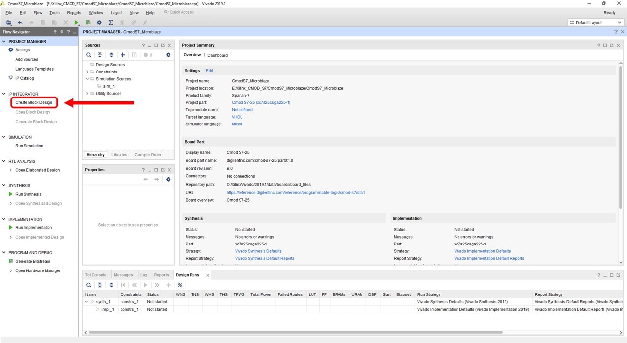
1.In order to add the MicroBlaze IP block, we will use the IP Integrator tool, which can be opened from the Flow Navigator on the left side of the window. Expand the IP Integrator tab and select Create Block Design.

image

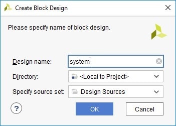
2.In the dialog box, give the block construct a name. I named it system. The directory location is where the block design will be stored, you can change it, but it is recommended to leave it as <local to the project>. Make sure Specify source set is set to Design Sources.

image

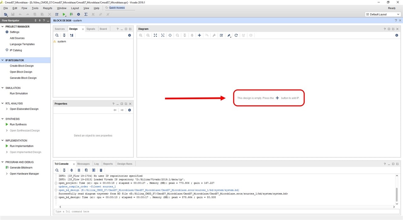
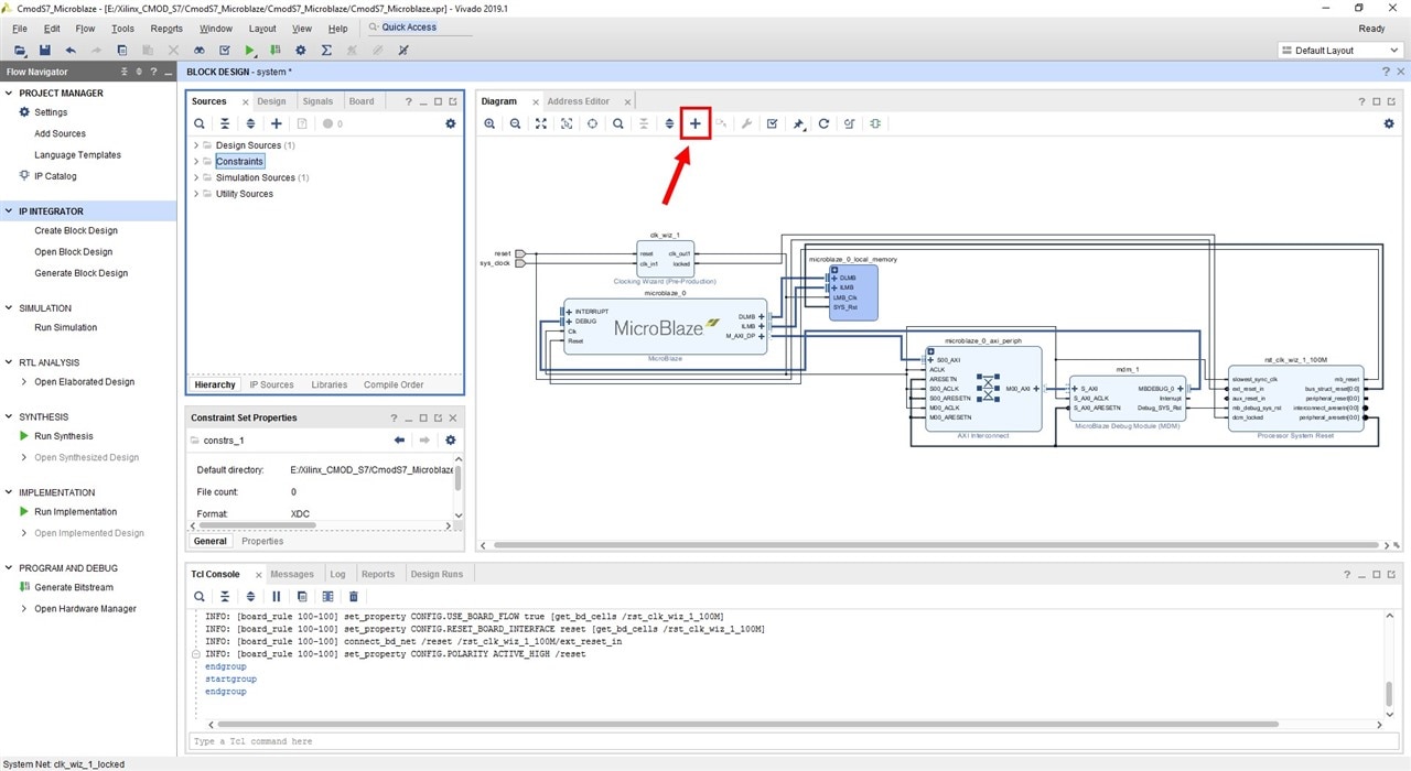
3.Most of the upper right of the Vivado window is taken up by the Diagram pane. This pane displays a graphical rendition of the current block design. In the center of the window is the inscription "This design is empty. Press the + button to add IP". Click on it to add an IP block.

image

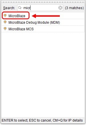
4.A dialog box pops up to select an IP block. In the Search line, enter microblaze and we are given three options. I choose the first MicroBlaze.

image

5.The MicroBlaze IP block has appeared on the Diagram panel. And in the same panel at the top, the inscription "Designer Assistance available. Run Block Automation" appeared highlighted in green.This inscription says that if any IP block has any presets, then we can see them by clicking on this inscription. We click on it.

image

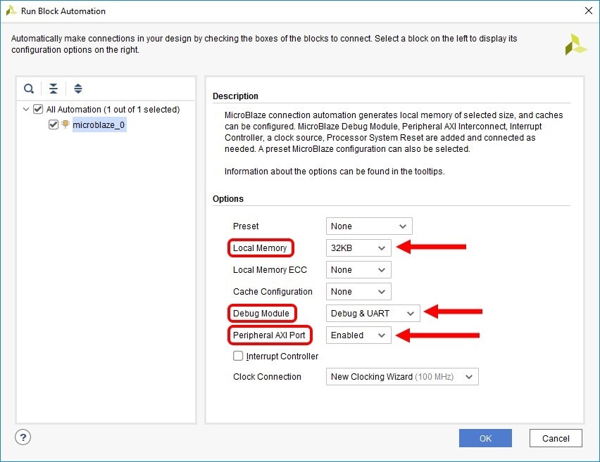
6.The "Run Block Automation" window will open, which allows you to very quickly configure the MicroBlaze processor system to the required parameters. The parameters that I chose are shown in the figure below. I installed 32KB of local memory, indicated debugging with UART and enabled AXI ports (Xilinx has all the peripherals connected to the processor via the AXI bus).

image

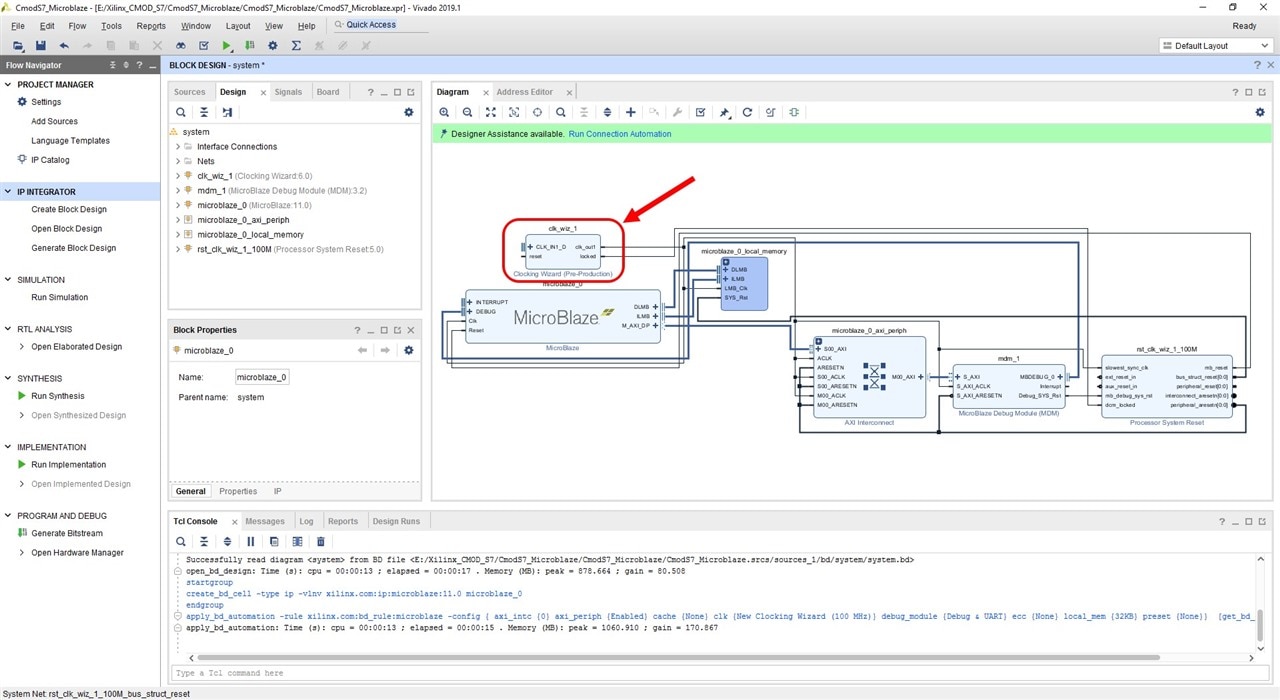
7.After pressing the OK button. The assembly of the presets that we indicated earlier will begin and after a short period of time we will see the MicroBlaze block with additional modules on the Diagram panel.

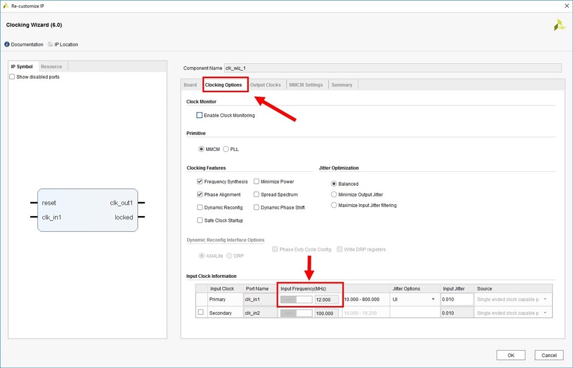
After that, we need to adjust the clock speed for our processor system. On the Diagram panel, double-click the left mouse button on the Clocking Wizard block.

image

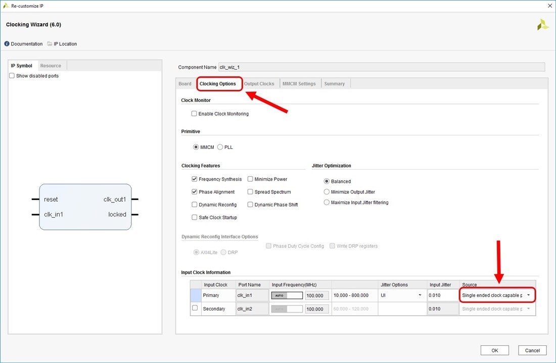
8.The Clocking Wizard block settings window opens. Click on the Clocking Options tab and in the Input Clock Information section at the end of the first first line in the Source column, select the Single ended clock capable pin parameter. Press the OK button.

image

9.After that, again click the inscription "Designer Assistance available. Run Block Automation".

image

10.In the Run Connection Automation window, check all the boxes so that Vivado will automatically configure and connect the Clocking Wizard block. Press the OK button.

image

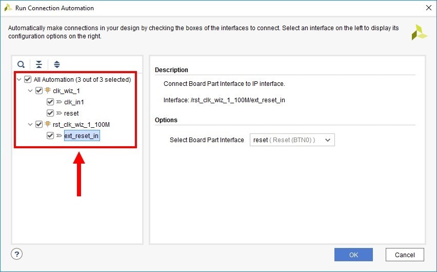
11.On the Diagram panel, we see that Vivado automatically connected the crystal oscillator installed on the Cmod S7 board to the input of the Clocking Wizard block and also connected the BTN0 button to the Reset input and connected the clk_out1 output to the processor system clock line.

image

image


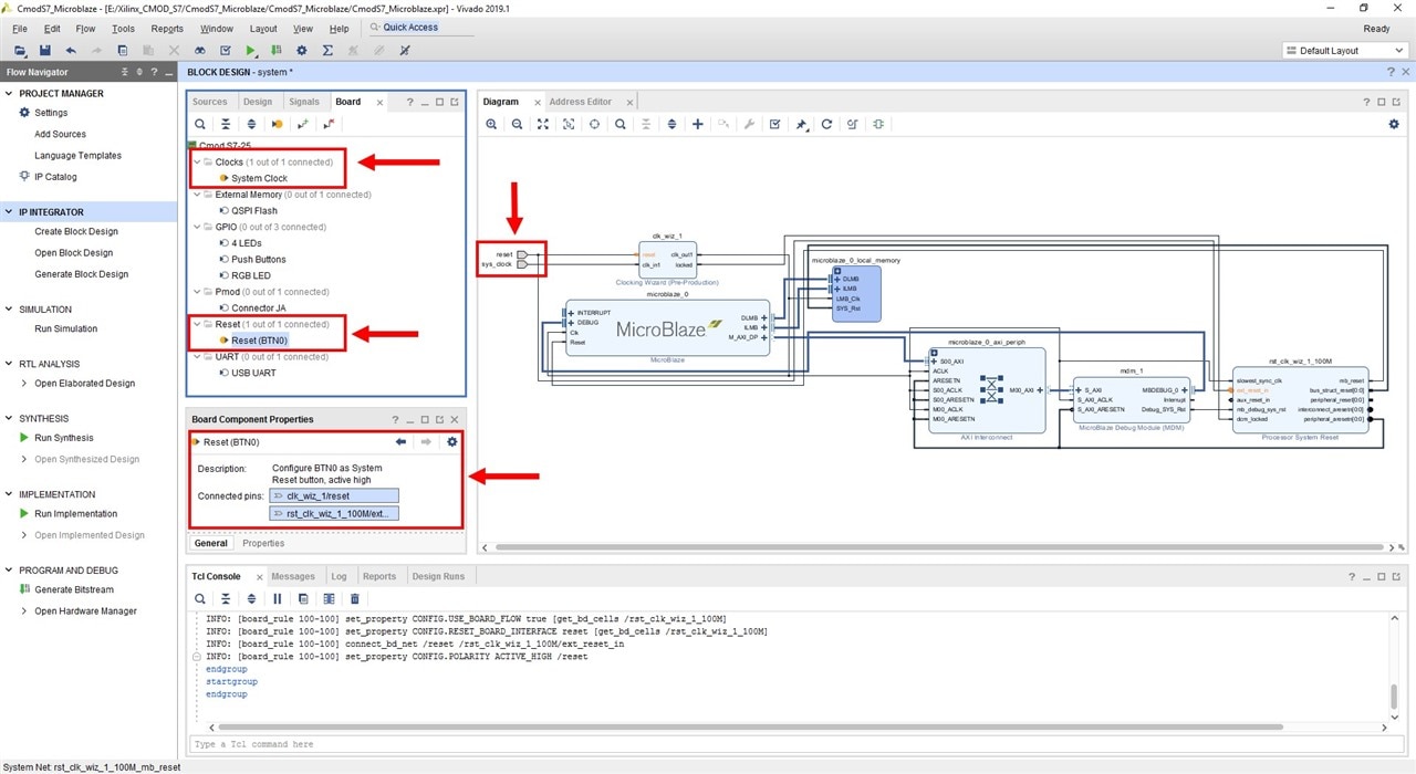
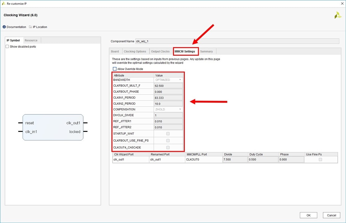
Vivado also automatically adjusted the clock speed and additional parameters according to the Cmod S7 board.

image

image

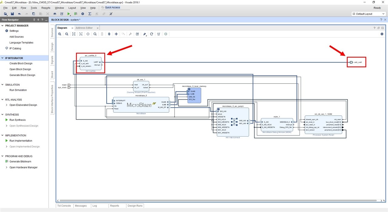
12.Now you need to configure the UART block to transfer data from the processor system to the computer. Click + on the Diagram panel.

image

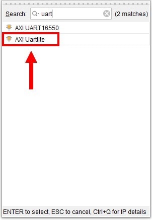
13.In the Search line, enter uart and select AXI Uartlite from the list.

image

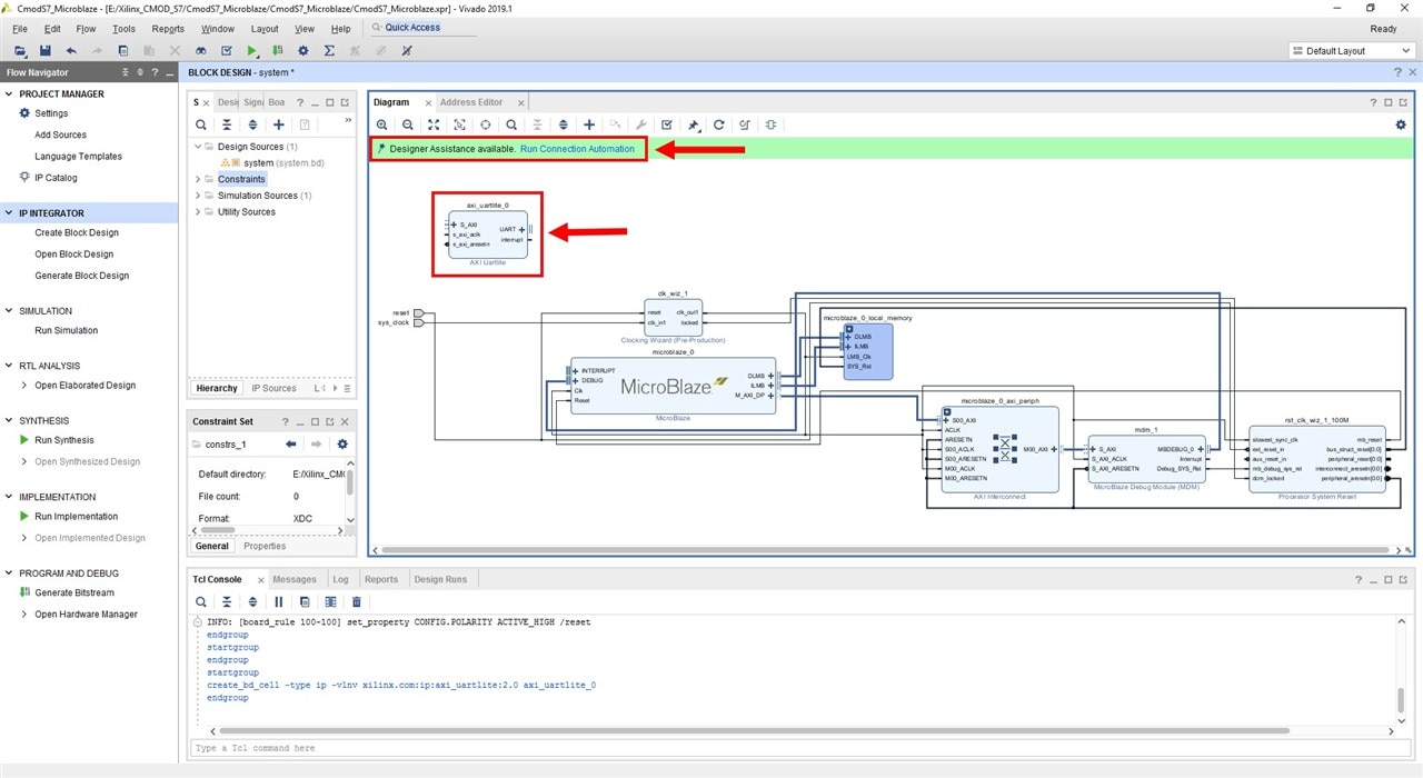
14.The AXI Uartlite block will appear on the Diagram panel. Again, click the inscription "Designer Assistance available. Run Block Automation".

image

15.In the "Run Connection Automation" window that appears, check all the boxes. Press the OK button.

image

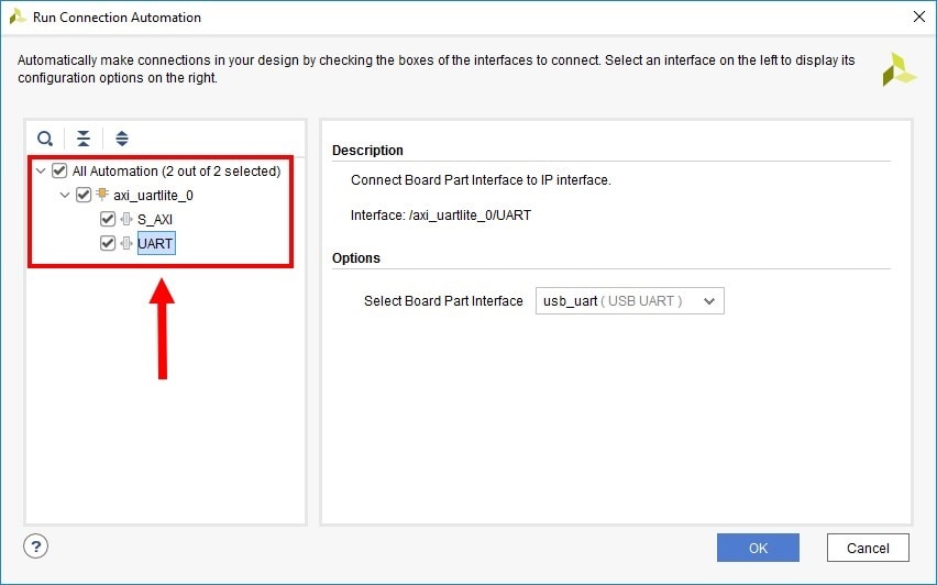
16.We see that Vivado automatically connected all the lines to the processor system and also brought out the Uart output.

image

  • Sign in to reply
element14 Community

element14 is the first online community specifically for engineers. Connect with your peers and get expert answers to your questions.

  • Members
  • Learn
  • Technologies
  • Challenges & Projects
  • Products
  • Store
  • About Us
  • Feedback & Support
  • FAQs
  • Terms of Use
  • Privacy Policy
  • Legal and Copyright Notices
  • Sitemap
  • Cookies

An Avnet Company © 2025 Premier Farnell Limited. All Rights Reserved.

Premier Farnell Ltd, registered in England and Wales (no 00876412), registered office: Farnell House, Forge Lane, Leeds LS12 2NE.

ICP 备案号 10220084.

Follow element14

  • X
  • Facebook
  • linkedin
  • YouTube