[Note: I am new in FPGA and just started learning it. I will share my understanding here. I may be wrong in some cases or something can be oversimplified.]
Introduction
Vehicle Number Plate Recognition (NPR) or License Plate Recognition (LPR) or Registration Plate Recognition (RPR) is an enhanced computer vision technology that connects vehicles without direct human connection through their number plates. Recognition of Vehicle License Number Plates (VLNP) is an important task. It is valuable in numerous applications, such as entrance admission, security, parking control, road traffic control, and speed control. An ANPR (Automatic Number Plate Recognition) is a system in which the image of the vehicle is captured through high definition cameras. The image is then used to detect vehicles of any type (car, van, bus, truck, and bike, etc.), its’ color (white, black, blue, etc.), and its’ model (Toyota Corolla, Honda Civic etc.). Furthermore, this image is processed using segmentation and OCR techniques to get the vehicle registration number in form of characters. Once the required information is extracted from VLNP, this information is sent to the control center for further processing. License Plate Recognition consists of three main phases:
1. License Plate Detection/Extraction
2. Character Segmentation and
3. Character Recognition.
Rapid development of the Field Programmable Gate Array (FPGA) offers an alternative way to provide acceleration for computationally intensive tasks such as digital signal and image processing. Its ability to perform parallel processing shows the potential in implementing a high-speed vision system. Out of numerous applications of computer vision, this project focuses on the hardware implementation of one that is commercially known as Automatic Number Plate Recognition (ANPR).
In recent years, the significant evolution of computer vision can be seen as it is making its way into an increasing number of application domains. The research and development in the field of computer or machine vision has defined methods for processing and analyzing images from real world to provide human capabilities of understanding images to machines and robots. There is a strong and growing demand for computer vision systems in the automotive domain. Intelligent cars that are available in the market nowadays are equipped with various camera-based driver assistance systems such as lane detection, night view assist, pedestrian detection and traffic sign recognition. These applications are required to work reliably in a large range of lighting and climatic conditions and to process a very high frame rate video signal in real-time. Besides those above-mentioned applications, the Automatic Number Plate Recognition (ANPR) is also one of the computer vision applications that is widely used in the automotive domain. However, it is better known as a surveillance technology rather than a driver assistance system. Vehicles are usually identified by their registration number which are easily readable by humans. But for machines, a plate number is a grey image defined as a mathematical function that represents light intensity at a certain point within an image. The ANPR application is implemented on FPGA as illustrated is suitable for a wide range of applications. The application is constructed using basic computer vision and image processing algorithms. Various hardware cores are developed for each algorithm that later can simply be reused by other vision applications.
What is FPGA?
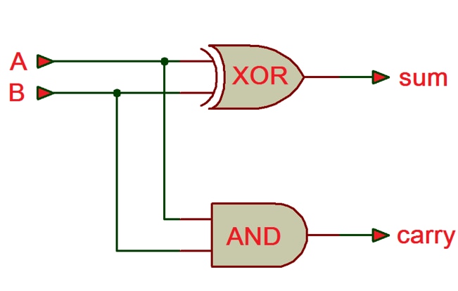
Any digital circuit can be made with basic logic gates like AND, OR, NOT, EX-OR, or universal gates like NAND. So, using lots of logic gates you can make a fully functional processor. An FPGA is a piece of silicon that has thousands of basic gates integrated inside the silicon. Using an FPGA you can make any digital device like a simple adder circuit to a complex processor, memory, or network controller. FPGA stands for Field Programmable Gate Array. As we know an FPGA has thousands of gates and for designing anything using an FPGA we need to make connections among those gates in a definite way. For example, for making a half adder like the following image we need to choose one X-OR gate and one AND gate and make the connection like the circuit. We choose the gates and make connections among them inside an FPGA using Hardware Description Language (HDL) like Verilog or VHDL. We can change the connection anytime to make another circuit and from that idea, the Field Programmable term comes.

One question can come into your mind, way we will not use Application Specific IC (ASIC) instead of FPGA. For example, we can use an adder IC directly instead of making an adder circuit using FPGA (of course we will not make such a simple thing using an FPGA). The answer is that the readymade IC for your specific work may not be available and making one for your own is only economically viable if you need it more than a few million pcs. Then you can say, OK I will solve my problem using a microcontroller or microprocessor. Again the answer is that the microprocessors are sequential in nature and if you have lots of work need to do simultaneously without any delay then FPGA is the only option.
The fact is that FPGAs are not so simple. Modern FPGA has lookup tables (LUT) instead of basic gates. A LUT can be programmed to implement any combinational logic equation. A combination of LUT and Flip Flop is called Configurable Logic Block (CLB). Modern FPGA consists of many thousands of CLBs which include local memory, arithmetic functions, and shift registers. For making a digital system these CLBs must be interconnected. An FPGA contains programmable interconnect which connects CLBs and distributes the clocks.
I recommend reading Programmable Devices I: Programmable Logic for a better understanding of FPGA if you are new to this.
How to get started with FPGA?
Maybe you are familiar with Arduino or any other microcontroller-based system development. FPGA and Microcontroller both are programmable devices. Without a program, they are just a piece of silicon and can do nothing. For microcontroller programming nowadays we use high-level language like C or C++. We then compile the program to generate a .hex file which we then upload to the target microcontroller. An IDE like Arduino IDE helps us to do all the tasks from a single tool.
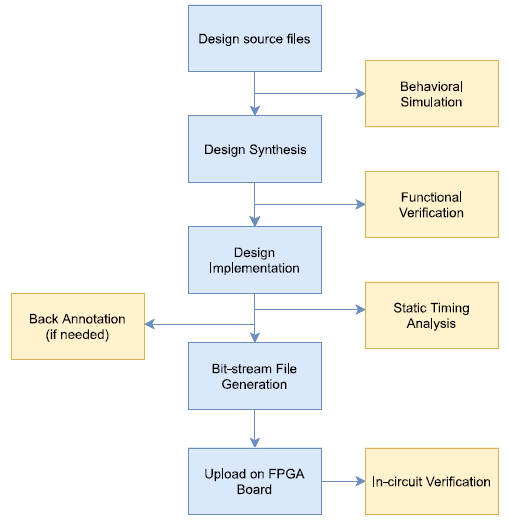
Unlike microcontroller, FPGAs are programmed using hardware description languages like Verilog or VHDL. After developing the HDL code the source file is synthesized. The synthesized file is then implemented (placement & route) to generate a Bit-stream file which is uploaded to the FPGA. The following block diagram gives an overview of the FPGA design flow. FPGA manufacturers usually provide their own IDE and using those IDE we can complete all the design steps from a single tool.

The Xilinx Spartan-7 FPGA
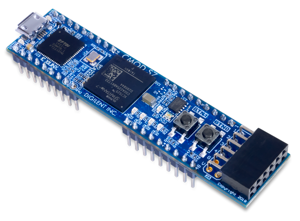
Definitely Xilinx is the leader in FPGA industry and Spartan-7 is the Xilinx's most cost effective design with the latest technology. We will use here a Spartan-7 (XC7S25-1CSGA225C) based FPGA development board from Digilant named as CMOD S7. The Digilent Cmod S7 is a small, 48-pin DIP form factor board built around a Xilinx Spartan 7 FPGA. 32 FPGA digital I/O signals, 2 FPGA analog input signals, an external power input rail, and ground are routed to 100-mil-spaced through-hole pins, making the Cmod S7 well suited for use with solderless breadboards. At just 0.7” by 3.05” inches, it can be loaded in a standard socket and used in embedded systems. The board also includes a programming ROM, clock source, USB programming and data transfer circuit, power supplies, LEDs, and buttons.

Digilant Official Cmod S7 Reference Manual is here.
Getting Started with Xilinx Spartan-7
For getting started with any FPGA it is always good to buy a development board. Lots of FPGA development board with different price range are available. As I already said I am going to use Digilant Cmod S7 board for my tutorial series you can buy one from here.
After getting the development board the next thing is to prepare your development environment. We are going to use Xilinx Vivado for our project. Follow the Digilant guide: Installing Vivado, Xilinx SDK, and Digilent Board Files for preparing your development environment.
Then for running your 'Hello World' program follow the Digilant guide: Getting Started with Vivado.
