


Over the last few years, FPGAs have moved from glue logic to computing platforms. They effectively provide a reconfigurable hardware platform for implementing logic and algorithms. Being fine-grained hardware, FPGAs are able to exploit the parallelism inherent within a hardware design while at the same time maintaining the reconfigurability and programmability of software. This has led to FPGAs being used as a platform for accelerating computationally intensive tasks. This is particularly seen in the field of image processing, where the FPGA-based acceleration of imaging algorithms has become mainstream.
Field programmable gate arrays (FPGAs) are increasingly being used for the implementation of image processing applications. This is especially the case for real-time embedded applications, where latency and power are important considerations. An FPGA embedded in a smart camera is able to perform much of the image processing directly as the image is streamed from the sensor, with the camera providing a processed output data stream, rather than a sequence of images. The parallelism of hardware is able to exploit the spatial (data level) and temporal (task level) parallelism implicit within many image processing tasks. Unfortunately, simply porting a software algorithm onto an FPGA often gives disappointing results, because many image processing algorithms have been optimized for a serial processor. It is usually necessary to transform the algorithm to efficiently exploit the parallelism and resources available on an FPGA.
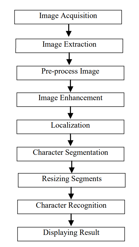
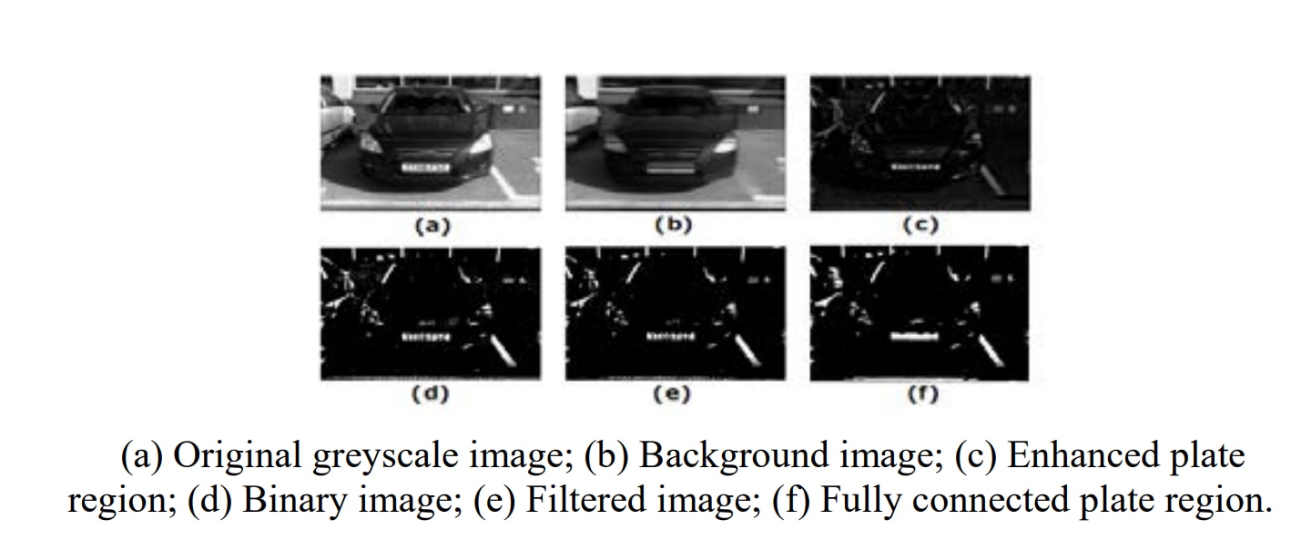
Automatic Number plate recognition (ANPR) may be found useful in many applications ranging from applications such as monitoring parking lots to identifying speeding vehicles in expressways. The procedure of implementing such systems may be found tedious due to problems such as: maintaining a constant distance with the rear view of the vehicle, varying lighting conditions, or the number plate being obstructed by some other object or dirt. Although the above-mentioned factors make the task of isolating and recognizing a number plate tedious, the speed of processing is a great concern because character recognition in real-time is vital in such applications. This research is focused mainly on the prime requirement for an improved number plate recognition system - the speed of processing. Hence, this system is based on a Field Programmable Gate Array (FPGA). Also, the implemented ANPR system has the ability to recognize characters of the number plate even if it is slightly obscured. The proposed Methodology of this project involves extracting the number plate from a rearview image of a vehicle and processing it in a suitable manner to perform character recognition using a template matching technique. This system is implemented based on several assumptions such as; the number plate being exposed to constant lighting conditions and that the frame of the number plate is captured for processing at a constant distance from the camera. These assumptions were made so that more focus could be given to faster processing, character recognition, and other concerns when using image processing techniques in hardware descriptive languages.
Before processing an image we need to load the image to the FPGA but Verilog cannot read image directly. To read a .bmp image in Verilog, the image is required to be converted from bitmap format to the hexadecimal format. An image can be easily converted to hexadecimal/binary data using Matlab, C, Python, etc. Below is a Matlab example code to convert a bitmap image to a .hex file. The input image size is 768x512 and the .hex file includes R, G, B data of the bitmap image.
For Verilog code, you can use $readmemh(for hexadecimal data) or $readmemb(for binary data) command to load a converted binary/hexadecimal text file directly. Example Verilog code for loading a text file or an image into FPGA using $readmemh.
b=imread('kodim24.bmp'); % 24-bit BMP image RGB888

k=1;
for i=512:-1:1 % image is written from the last row to the first row
for j=1:768
a(k)=b(i,j,1);
a(k+1)=b(i,j,2);
a(k+2)=b(i,j,3);
k=k+3;
end
end
fid = fopen('kodim24.hex', 'wt');
fprintf(fid, '%x\n', a);
disp('Text file write done');disp(' ');
fclose(fid);
% fpga4student.com FPGA projects, Verilog projects, VHDL projects
To read the image hexadecimal data file, Verilog uses this command: $readmemh or $readmemb if the image data is in a binary text file. After reading the image .hex file, the RGB image data are saved into memory and read out for processing.
Below is the Verilog code to the image reading:
/******************************************************************************/
/******************  Module for reading image     **************/
/******************************************************************************/
`include "parameter.v"       // Include definition file

module image_read
#(
  parameter     WIDTH  = 768,   // Image width
         HEIGHT  = 512,   // Image height
  INFILE  = "./img/kodim01.hex",  // image file
  START_UP_DELAY = 100, // Delay during start up time
  HSYNC_DELAY = 160,// Delay between HSYNC pulses
  VALUE= 100, // value for Brightness operation
  THRESHOLD= 90, // Threshold value for Threshold operation
  SIGN=1         // Sign value using for brightness operation
  // SIGN = 0: Brightness subtraction
  // SIGN = 1: Brightness addition
)
(
  input HCLK,          // clock
  input HRESETn,         // Reset (active low)
  output VSYNC,        // Vertical synchronous pulse
 // This signal is often a way to indicate that one entire image is transmitted.
 // Just create and is not used, will be used once a video or many images are transmitted.
  output reg HSYNC,        // Horizontal synchronous pulse
 // An HSYNC indicates that one line of the image is transmitted.
 // Used to be a horizontal synchronous signals for writing bmp file.
  output reg [7:0]  DATA_R0,  // 8 bit Red data (even)
  output reg [7:0]  DATA_G0,  // 8 bit Green data (even)
  output reg [7:0]  DATA_B0,  // 8 bit Blue data (even)
  output reg [7:0]  DATA_R1,  // 8 bit Red  data (odd)
  output reg [7:0]  DATA_G1,  // 8 bit Green data (odd)
  output reg [7:0]  DATA_B1,  // 8 bit Blue data (odd)
  // Process and transmit 2 pixels in parallel to make the process faster, you can modify to transmit 1 pixels or more if needed
  output     ctrl_done     // Done flag
);
//-------------------------------------------------
// Internal Signals
//-------------------------------------------------
parameter sizeOfWidth = 8;   // data width
parameter sizeOfLengthReal = 1179648;   // image data : 1179648 bytes: 512 * 768 *3
// local parameters for FSM
localparam  ST_IDLE  = 2'b00,// idle state
   ST_VSYNC = 2'b01,// state for creating vsync
   ST_HSYNC = 2'b10,// state for creating hsync
   ST_DATA  = 2'b11;// state for data processing
reg [1:0] cstate,   // current state
nstate;    // next state
reg start;         // start signal: trigger Finite state machine beginning to operate
reg HRESETn_d;   // delayed reset signal: use to create start signal
reg   ctrl_vsync_run; // control signal for vsync counter
reg [8:0] ctrl_vsync_cnt; // counter for vsync
reg   ctrl_hsync_run; // control signal for hsync counter
reg [8:0] ctrl_hsync_cnt; // counter  for hsync
reg   ctrl_data_run; // control signal for data processing
reg [7 : 0]   total_memory [0 : sizeOfLengthReal-1];// memory to store  8-bit data image
// temporary memory to save image data : size will be WIDTH*HEIGHT*3
integer temp_BMP   [0 : WIDTH*HEIGHT*3 - 1];
integer org_R  [0 : WIDTH*HEIGHT - 1];  // temporary storage for R component
integer org_G  [0 : WIDTH*HEIGHT - 1]; // temporary storage for G component
integer org_B  [0 : WIDTH*HEIGHT - 1]; // temporary storage for B component
// counting variables
integer i, j;
// temporary signals for calculation: details in the paper.
integer tempR0,tempR1,tempG0,tempG1,tempB0,tempB1; // temporary variables in contrast and brightness operation

integer value,value1,value2,value4;// temporary variables in invert and threshold operation
reg [ 9:0] row; // row index of the image
reg [10:0] col; // column index of the image
reg [18:0] data_count; // data counting for entire pixels of the image
//-------------------------------------------------//
// -------- Reading data from input file ----------//
//-------------------------------------------------//
initial begin
    $readmemh(INFILE,total_memory,0,sizeOfLengthReal-1); // read file from INFILE
end
// use 3 intermediate signals RGB to save image data
always@(start) begin
    if(start == 1'b1) begin
        for(i=0; i<WIDTH*HEIGHT*3 ; i=i+1) begin
            temp_BMP[i] = total_memory[i+0][7:0];
        end

        for(i=0; i<HEIGHT; i=i+1) begin
            for(j=0; j<WIDTH; j=j+1) begin
     // Matlab code writes image from the last row to the first row
     // Verilog code does the same in reading to correctly save image pixels into 3 separate RGB mem
                org_R[WIDTH*i+j] = temp_BMP[WIDTH*3*(HEIGHT-i-1)+3*j+0]; // save Red component
                org_G[WIDTH*i+j] = temp_BMP[WIDTH*3*(HEIGHT-i-1)+3*j+1];// save Green component
                org_B[WIDTH*i+j] = temp_BMP[WIDTH*3*(HEIGHT-i-1)+3*j+2];// save Blue component
            end
        end
    end
end
//----------------------------------------------------//
// ---Begin to read image file once reset was high ---//
// ---by creating a starting pulse (start)------------//
//----------------------------------------------------//
always@(posedge HCLK, negedge HRESETn)
begin
    if(!HRESETn) begin
        start <= 0;
  HRESETn_d <= 0;
    end
    else begin           //          ______
        HRESETn_d <= HRESETn;       //        |  |
  if(HRESETn == 1'b1 && HRESETn_d == 1'b0)  // __0___| 1 |___0____ : starting pulse
   start <= 1'b1;
  else
   start <= 1'b0;
    end
end
//-----------------------------------------------------------------------------------------------//
// Finite state machine for reading RGB888 data from memory and creating hsync and vsync pulses --//
//-----------------------------------------------------------------------------------------------//
always@(posedge HCLK, negedge HRESETn)
begin
    if(~HRESETn) begin
        cstate <= ST_IDLE;
    end
    else begin
        cstate <= nstate; // update next state
    end
end
//-----------------------------------------//
//--------- State Transition --------------//
//-----------------------------------------//
// IDLE . VSYNC . HSYNC . DATA
always @(*) begin
 case(cstate)
  ST_IDLE: begin
   if(start)
    nstate = ST_VSYNC;
   else
    nstate = ST_IDLE;
  end
  ST_VSYNC: begin
   if(ctrl_vsync_cnt == START_UP_DELAY)
    nstate = ST_HSYNC;
   else
    nstate = ST_VSYNC;
  end
  ST_HSYNC: begin
   if(ctrl_hsync_cnt == HSYNC_DELAY)
    nstate = ST_DATA;
   else
    nstate = ST_HSYNC;
  end
  ST_DATA: begin
   if(ctrl_done)
    nstate = ST_IDLE;
   else begin
    if(col == WIDTH - 2)
     nstate = ST_HSYNC;
    else
     nstate = ST_DATA;
   end
  end
 endcase
end
// ------------------------------------------------------------------- //
// --- counting for time period of vsync, hsync, data processing ----  //
// ------------------------------------------------------------------- //
always @(*) begin
 ctrl_vsync_run = 0;
 ctrl_hsync_run = 0;
 ctrl_data_run  = 0;
 case(cstate)
  ST_VSYNC:  begin ctrl_vsync_run = 1; end  // trigger counting for vsync
  ST_HSYNC:  begin ctrl_hsync_run = 1; end // trigger counting for hsync
  ST_DATA:  begin ctrl_data_run  = 1; end // trigger counting for data processing
 endcase
end
// counters for vsync, hsync
always@(posedge HCLK, negedge HRESETn)
begin
    if(~HRESETn) begin
        ctrl_vsync_cnt <= 0;
  ctrl_hsync_cnt <= 0;
    end
    else begin
        if(ctrl_vsync_run)
   ctrl_vsync_cnt <= ctrl_vsync_cnt + 1; // counting for vsync
  else
   ctrl_vsync_cnt <= 0;

        if(ctrl_hsync_run)
   ctrl_hsync_cnt <= ctrl_hsync_cnt + 1; // counting for hsync
  else
   ctrl_hsync_cnt <= 0;
    end
end
// counting column and row index  for reading memory
always@(posedge HCLK, negedge HRESETn)
begin
    if(~HRESETn) begin
        row <= 0;
  col <= 0;
    end
 else begin
  if(ctrl_data_run) begin
   if(col == WIDTH - 2) begin
    row <= row + 1;
   end
   if(col == WIDTH - 2)
    col <= 0;
   else
    col <= col + 2; // reading 2 pixels in parallel
  end
 end
end
//-------------------------------------------------//
//----------------Data counting---------- ---------//
//-------------------------------------------------//
always@(posedge HCLK, negedge HRESETn)
begin
    if(~HRESETn) begin
        data_count <= 0;
    end
    else begin
        if(ctrl_data_run)
   data_count <= data_count + 1;
    end
end
assign VSYNC = ctrl_vsync_run;
assign ctrl_done = (data_count == 196607)? 1'b1: 1'b0; // done flag