For image recognition first, we need to capture an image using the FPGA. We will use an OV7670 CMOS camera for capturing real-time images for our project. The OV7670 is a CMOS parallel camera with VGA resolution from OmniVision. The camera has an image array of 656x488 pixels, of which 640x480 pixels are active. The camera can operate from 1.7 to 3V. The camera interface consists of a parallel 8-bit bus, synchronization signals VSYNC and HSYNC, pixel clock, master clock, and reset and power down signals.


Source: https://www.hackster.io/dhq/fpga-camera-system-14d6ea
The camera interfacing code consists of two main modules. The input capture image and the camera configuration image. The input capture code is responsible for transmitting the pixels to the frame buffer. This module decodes the pixels coming from the camera. Each pixel is packed into 2 consecutive bytes. The Input capture module converts this to RGB444. This is done to save space since the VGA interface uses an RGB444 interface. The camera supports multiple pixel image formats however the one selected in this application is RGB565 meaning Red, Green, and Blue gets 5, 6, and 5 pixels each respectively.

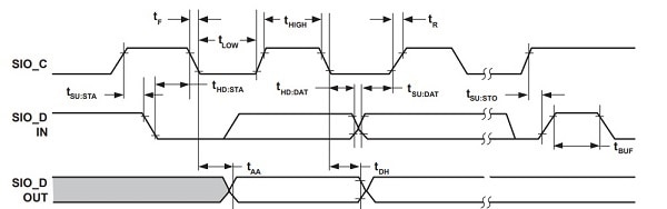
The camera is configured via SCCB (Serial Camera Communication Bus). This is mostly compatible with I2C.

LIBRARY ieee;
USE ieee.std_logic_1164.ALL;
USE ieee.numeric_std.ALL;

LIBRARY blk_mem_gen_v8_4_0;
USE blk_mem_gen_v8_4_0.blk_mem_gen_v8_4_0;

ENTITY frame_buffer IS
  PORT (
    clka : IN STD_LOGIC;
    wea : IN STD_LOGIC_VECTOR(0 DOWNTO 0);
    addra : IN STD_LOGIC_VECTOR(16 DOWNTO 0);
    dina : IN STD_LOGIC_VECTOR(11 DOWNTO 0);
    clkb : IN STD_LOGIC;
    addrb : IN STD_LOGIC_VECTOR(16 DOWNTO 0);
    doutb : OUT STD_LOGIC_VECTOR(11 DOWNTO 0)
  );
END frame_buffer;
The top-level VHDL sample code for the OV7670 camera for an FPGA is:
library IEEE;
use IEEE.STD_LOGIC_1164.ALL;
entity top_level is
    Port ( clk100          : in  STD_LOGIC;
           btnl            : in  STD_LOGIC;
           btnc            : in  STD_LOGIC;
           btnr            : in  STD_LOGIC;
           config_finished : out STD_LOGIC;

           vga_hsync : out  STD_LOGIC;
           vga_vsync : out  STD_LOGIC;
           vga_r     : out  STD_LOGIC_vector(3 downto 0);
           vga_g     : out  STD_LOGIC_vector(3 downto 0);
           vga_b     : out  STD_LOGIC_vector(3 downto 0);

           ov7670_pclk  : in  STD_LOGIC;
           ov7670_xclk  : out STD_LOGIC;
           ov7670_vsync : in  STD_LOGIC;
           ov7670_href  : in  STD_LOGIC;
           ov7670_data  : in  STD_LOGIC_vector(7 downto 0);
           ov7670_sioc  : out STD_LOGIC;
           ov7670_siod  : inout STD_LOGIC;
           ov7670_pwdn  : out STD_LOGIC;
           ov7670_reset : out STD_LOGIC
           );
end top_level;
architecture Behavioral of top_level is

 COMPONENT VGA
 PORT(
  CLK25 : IN std_logic;
                rez_160x120 : IN std_logic;
                rez_320x240 : IN std_logic;
  Hsync : OUT std_logic;
  Vsync : OUT std_logic;
  Nblank : OUT std_logic;
  clkout : OUT std_logic;
  activeArea : OUT std_logic;
  Nsync : OUT std_logic
  );
 END COMPONENT;

 COMPONENT ov7670_controller
 PORT(
  clk : IN std_logic;
  resend : IN std_logic;
  siod : INOUT std_logic;
  config_finished : OUT std_logic;
  sioc : OUT std_logic;
  reset : OUT std_logic;
  pwdn : OUT std_logic;
  xclk : OUT std_logic
  );
 END COMPONENT;

 COMPONENT debounce
 PORT(
  clk : IN std_logic;
  i : IN std_logic;
  o : OUT std_logic
  );
 END COMPONENT;

 COMPONENT frame_buffer
  PORT (
      clka : IN STD_LOGIC;
      wea : IN STD_LOGIC_VECTOR(0 DOWNTO 0);
      addra : IN STD_LOGIC_VECTOR(16 DOWNTO 0);
      dina : IN STD_LOGIC_VECTOR(11 DOWNTO 0);
      clkb : IN STD_LOGIC;
      addrb : IN STD_LOGIC_VECTOR(16 DOWNTO 0);
      doutb : OUT STD_LOGIC_VECTOR(11 DOWNTO 0)
    );
 END COMPONENT;
 COMPONENT ov7670_capture
 PORT(
                rez_160x120 : IN std_logic;
                rez_320x240 : IN std_logic;
  pclk : IN std_logic;
  vsync : IN std_logic;
  href : IN std_logic;
  d : IN std_logic_vector(7 downto 0);
  addr : OUT std_logic_vector(18 downto 0);
  dout : OUT std_logic_vector(11 downto 0);
  we : OUT std_logic
  );
 END COMPONENT;
 COMPONENT RGB
 PORT(
  Din : IN std_logic_vector(11 downto 0);
  Nblank : IN std_logic;
  R : OUT std_logic_vector(7 downto 0);
  G : OUT std_logic_vector(7 downto 0);
  B : OUT std_logic_vector(7 downto 0)
  );
 END COMPONENT;
 component clocking
 port (
                CLK_100           : in     std_logic;
                -- Clock out ports
                CLK_50          : out    std_logic;
                CLK_25          : out    std_logic);
 end component;
 COMPONENT Address_Generator
 PORT(
  CLK25       : IN  std_logic;
                rez_160x120 : IN std_logic;
                rez_320x240 : IN std_logic;
  enable      : IN  std_logic;
                vsync       : in  STD_LOGIC;
  address     : OUT std_logic_vector(18 downto 0)
  );
 END COMPONENT;
   signal clk_camera : std_logic;
   signal clk_vga    : std_logic;
   signal wren       : std_logic_vector(0 downto 0);
   signal resend     : std_logic;
   signal nBlank     : std_logic;
   signal vSync      : std_logic;
   signal nSync      : std_logic;

   signal wraddress  : std_logic_vector(18 downto 0);
   signal wrdata     : std_logic_vector(11 downto 0);

   signal rdaddress  : std_logic_vector(18 downto 0);
   signal rddata     : std_logic_vector(11 downto 0);
   signal red,green,blue : std_logic_vector(7 downto 0);
   signal activeArea : std_logic;

   signal rez_160x120 : std_logic;
   signal rez_320x240 : std_logic;
   signal size_select: std_logic_vector(1 downto 0);
   signal rd_addr,wr_addr  : std_logic_vector(16 downto 0);
begin
   vga_r <= red(7 downto 4);
   vga_g <= green(7 downto 4);
   vga_b <= blue(7 downto 4);

   rez_160x120 <= btnl;
   rez_320x240 <= btnr;
   your_instance_name : clocking
     port map
      (-- Clock in ports
       CLK_100 => CLK100,
       -- Clock out ports
       CLK_50 => CLK_camera,
       CLK_25 => CLK_vga);
       vga_vsync <= vsync;

 Inst_VGA: VGA PORT MAP(
  CLK25      => clk_vga,
                rez_160x120 => rez_160x120,
                rez_320x240 => rez_320x240,
  clkout     => open,
  Hsync      => vga_hsync,
  Vsync      => vsync,
  Nblank     => nBlank,
  Nsync      => nsync,
                activeArea => activeArea
 );
 Inst_debounce: debounce PORT MAP(
  clk => clk_vga,
  i   => btnc,
  o   => resend
 );
 Inst_ov7670_controller: ov7670_controller PORT MAP(
  clk             => clk_camera,
  resend          => resend,
  config_finished => config_finished,
  sioc            => ov7670_sioc,
  siod            => ov7670_siod,
  reset           => ov7670_reset,
  pwdn            => ov7670_pwdn,
  xclk            => ov7670_xclk
 );
 size_select <= btnl&btnr;

    with size_select select
    rd_addr <= rdaddress(18 downto 2) when "00",
        rdaddress(16 downto 0) when "01",
        rdaddress(16 downto 0) when "10",
        rdaddress(16 downto 0) when "11";

   with size_select select
    wr_addr <= wraddress(18 downto 2) when "00",
            wraddress(16 downto 0) when "01",
            wraddress(16 downto 0) when "10",
            wraddress(16 downto 0) when "11";
 Inst_frame_buffer: frame_buffer PORT MAP(
  addrb => rd_addr,
  clkb   => clk_vga,
  doutb        => rddata,

  clka   => ov7670_pclk,
  addra => wr_addr,
  dina      => wrdata,
  wea      => wren
 );
 Inst_ov7670_capture: ov7670_capture PORT MAP(
  pclk  => ov7670_pclk,
                rez_160x120 => rez_160x120,
                rez_320x240 => rez_320x240,
  vsync => ov7670_vsync,
  href  => ov7670_href,
  d     => ov7670_data,
  addr  => wraddress,
  dout  => wrdata,
  we    => wren(0)
 );
 Inst_RGB: RGB PORT MAP(
  Din => rddata,
  Nblank => activeArea,
  R => red,
  G => green,
  B => blue
 );
 Inst_Address_Generator: Address_Generator PORT MAP(
  CLK25 => clk_vga,
                rez_160x120 => rez_160x120,
                rez_320x240 => rez_320x240,
  enable => activeArea,
                vsync  => vsync,
  address => rdaddress
 );
end Behavioral;
The main code was collected from here.
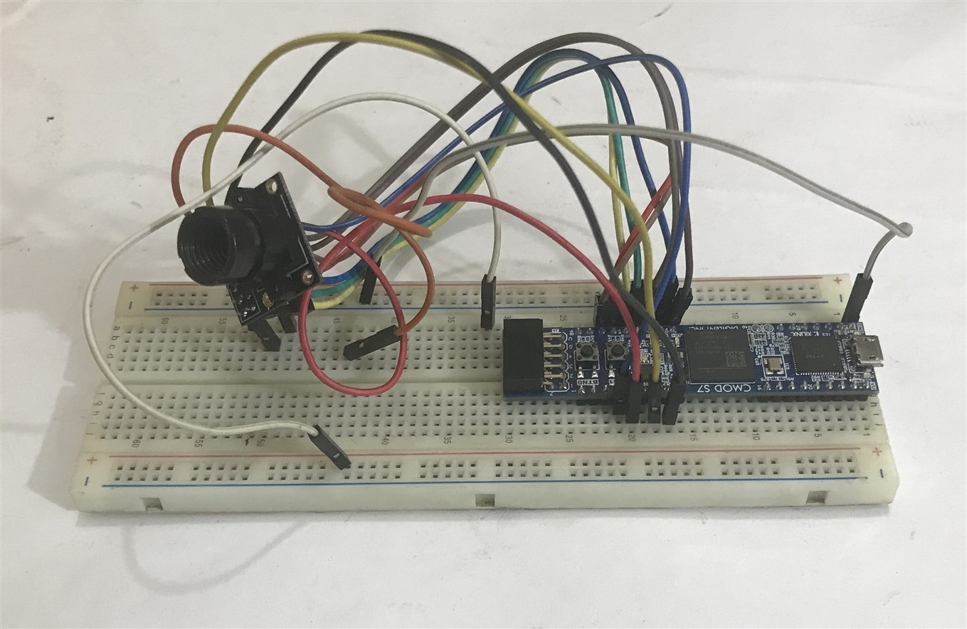
Camera Connection to Cmod 7 board