element14 Community
element14 Community
    Register Log In
  • Site
  • Search
  • Log In Register
  • Community Hub
    Community Hub
    • What's New on element14
    • Feedback and Support
    • Benefits of Membership
    • Personal Blogs
    • Members Area
    • Achievement Levels
  • Learn
    Learn
    • Ask an Expert
    • eBooks
    • element14 presents
    • Learning Center
    • Tech Spotlight
    • STEM Academy
    • Webinars, Training and Events
    • Learning Groups
  • Technologies
    Technologies
    • 3D Printing
    • FPGA
    • Industrial Automation
    • Internet of Things
    • Power & Energy
    • Sensors
    • Technology Groups
  • Challenges & Projects
    Challenges & Projects
    • Design Challenges
    • element14 presents Projects
    • Project14
    • Arduino Projects
    • Raspberry Pi Projects
    • Project Groups
  • Products
    Products
    • Arduino
    • Avnet & Tria Boards Community
    • Dev Tools
    • Manufacturers
    • Multicomp Pro
    • Product Groups
    • Raspberry Pi
    • RoadTests & Reviews
  • About Us
  • Store
    Store
    • Visit Your Store
    • Choose another store...
      • Europe
      •  Austria (German)
      •  Belgium (Dutch, French)
      •  Bulgaria (Bulgarian)
      •  Czech Republic (Czech)
      •  Denmark (Danish)
      •  Estonia (Estonian)
      •  Finland (Finnish)
      •  France (French)
      •  Germany (German)
      •  Hungary (Hungarian)
      •  Ireland
      •  Israel
      •  Italy (Italian)
      •  Latvia (Latvian)
      •  
      •  Lithuania (Lithuanian)
      •  Netherlands (Dutch)
      •  Norway (Norwegian)
      •  Poland (Polish)
      •  Portugal (Portuguese)
      •  Romania (Romanian)
      •  Russia (Russian)
      •  Slovakia (Slovak)
      •  Slovenia (Slovenian)
      •  Spain (Spanish)
      •  Sweden (Swedish)
      •  Switzerland(German, French)
      •  Turkey (Turkish)
      •  United Kingdom
      • Asia Pacific
      •  Australia
      •  China
      •  Hong Kong
      •  India
      • Japan
      •  Korea (Korean)
      •  Malaysia
      •  New Zealand
      •  Philippines
      •  Singapore
      •  Taiwan
      •  Thailand (Thai)
      • Vietnam
      • Americas
      •  Brazil (Portuguese)
      •  Canada
      •  Mexico (Spanish)
      •  United States
      Can't find the country/region you're looking for? Visit our export site or find a local distributor.
  • Translate
  • Profile
  • Settings
Summer of FPGA
  • Challenges & Projects
  • Design Challenges
  • Summer of FPGA
  • More
  • Cancel
Summer of FPGA
Blog Security Hardware Accelerator #3 Create first Block Design and Add Microblaze Core.
  • Blog
  • Forum
  • Documents
  • Files
  • Mentions
  • Sub-Groups
  • Tags
  • More
  • Cancel
  • New
  • Share
  • More
  • Cancel
Group Actions
  • Group RSS
  • More
  • Cancel
Engagement
  • Author Author: fyaocn
  • Date Created: 6 Dec 2021 7:19 AM Date Created
  • Views 1381 views
  • Likes 5 likes
  • Comments 1 comment
Related
Recommended

Security Hardware Accelerator #3 Create first Block Design and Add Microblaze Core.

fyaocn
fyaocn
6 Dec 2021

1. Add Microblaze Core First

It is easy to start with template. But that is not FPGA born to be. I start from scratch, add soft-core, UART, GPIO, peripherals. Then coding with Verilog to make the project run. 

2. Create first Block Design 

2.1 Click the Create Block Design button in the IP Integrator dropdown of Vivado's Flow Navigator pane. A block design provides a visual representation of the hardware design, and can be used to easily connect and configure IP cores.The two fields should be left as defaults with your customized Project Name.

image

image

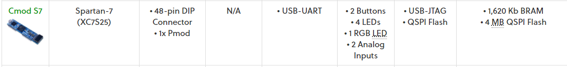
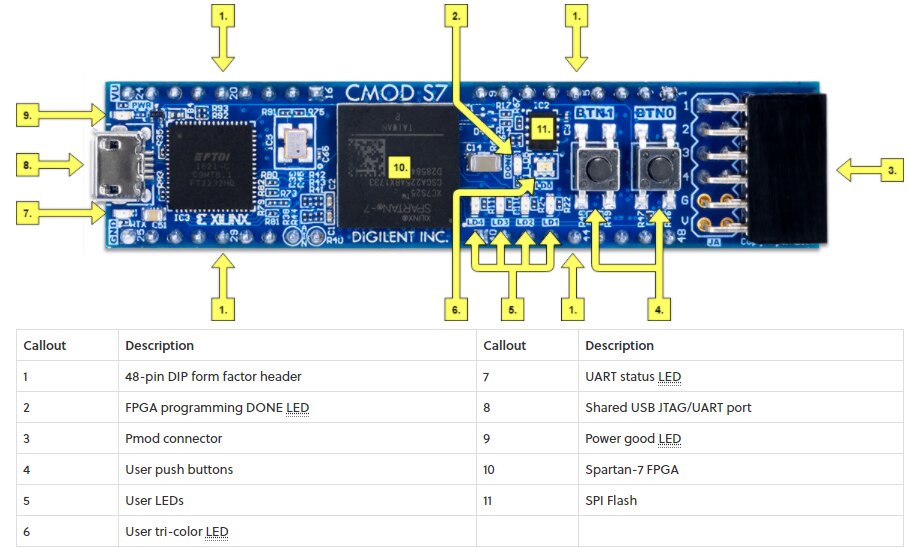
Then add a Microblaze soft-core Processor IP to a Block Designroblaze processor IP to instantiate a processor within the FPGA design, refer to Programmable Logic - Digilent Reference, find CMOD-S7 with brief specifications

image

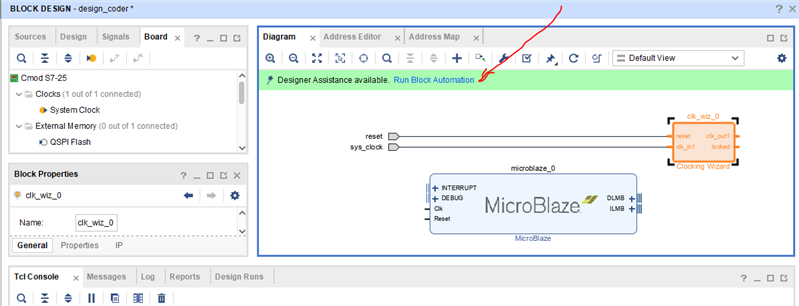
An external clock should be added to the block design. Open the Board tab, and find the system clock. Right-click on it and select Connect Board Component.

image

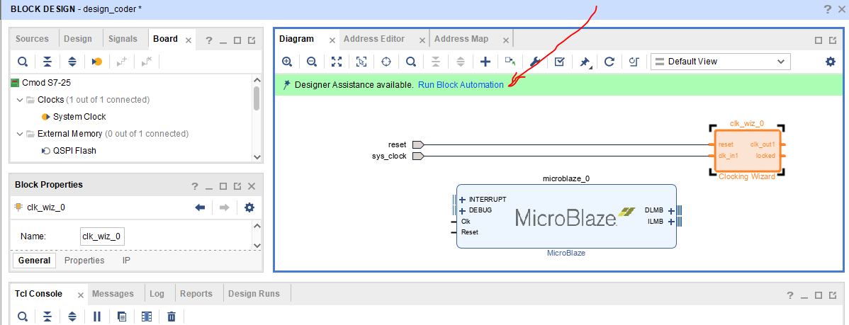
An external reset port added to the design. Click the Run Connection Automation button in the green Designer Assistance toolbar. 

image

BTN0 is set as Reset Button,

image

Select Polarity,

image

Double click to modify the Clock Property
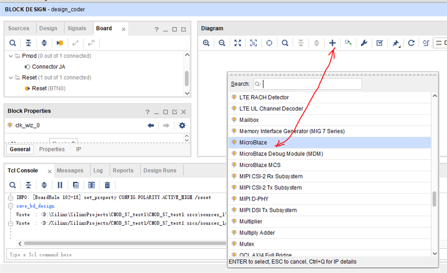
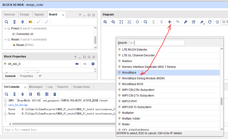
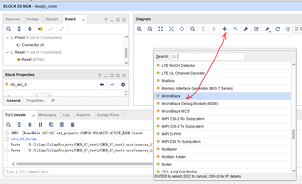
image

Now, use the Add IP button (image) to add the MicroBlaze IP to the design. 

image

image

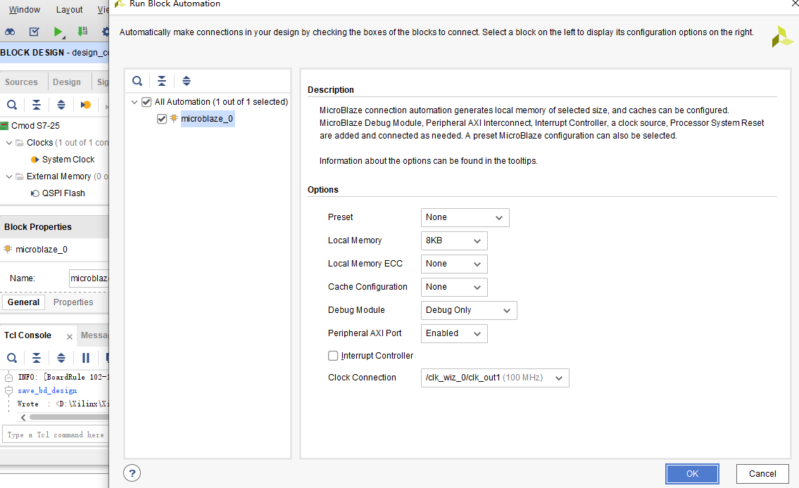
Run Block Automation dialog, specify settings and make right the first time or it would be better to delete the core and add again than modify it.

image

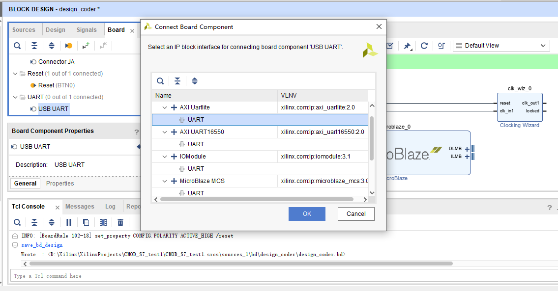
Find the USB UART interface in the Board tab, right click on it, and select Connect Board Component to add UART

image

Run Auto Block Connect , then run Auto connection

image

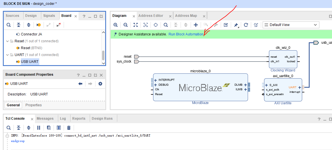
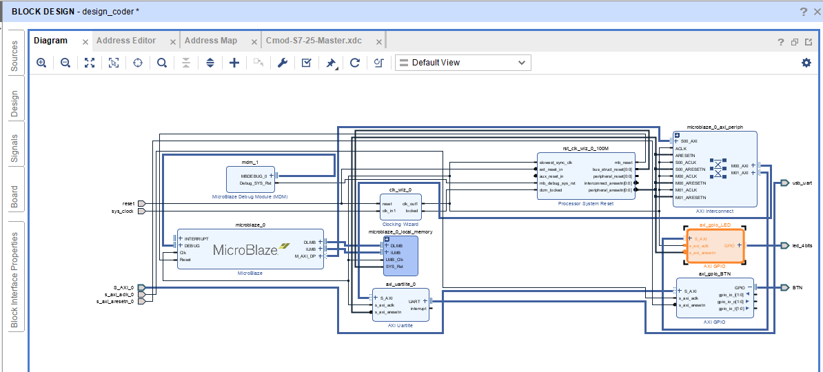
Amazingly, neccessary blocks are added and connected automatically. 

Of course, function shall be verified later.


3. Add GPIO Peripherals

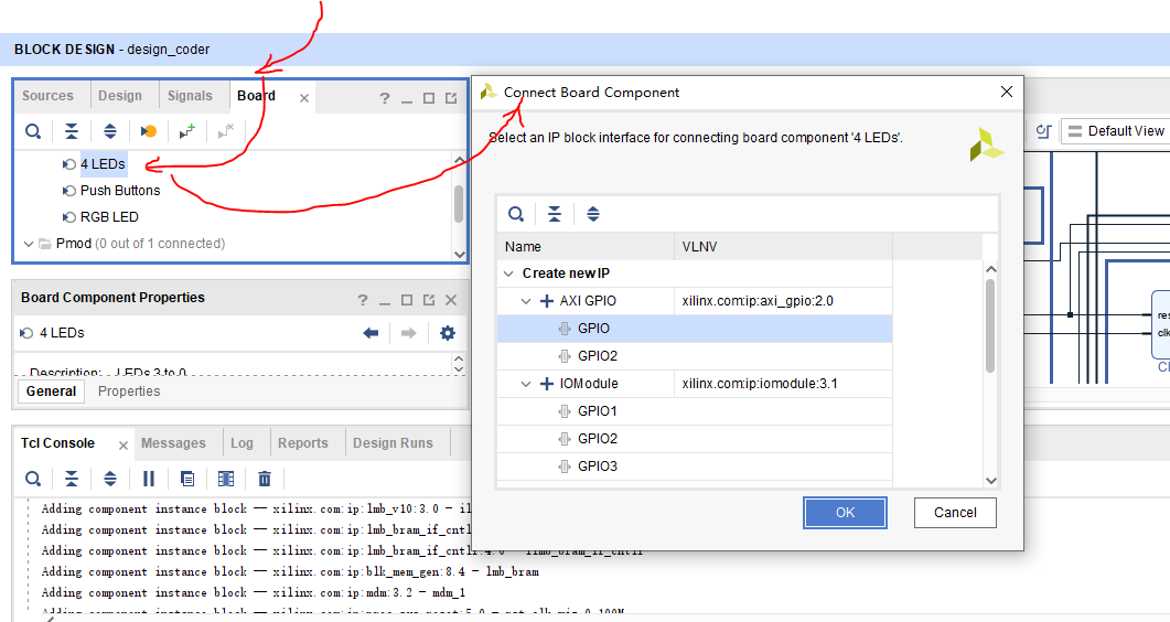
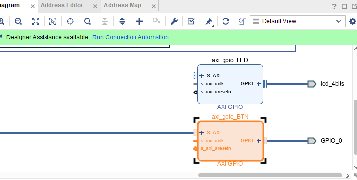
3.1 Find the GPIO section in Board Frame, right click on an LED interface, and select the Connect Board Interface option.

image

In the dialog that pops up, choose the “GPIO” interface (not GPIO2) of a new AXI GPIO IP

image

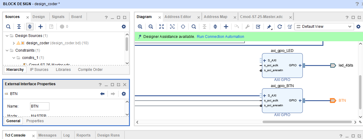
Manually addeda second AXI GPIO IP and manually constrained with an XDC file as Button. Click the Add IP button () and search for “AXI GPIO”. Then rename it to axi_gpio_BTN

image

Clicking on the text “GPIO”, right click on the highlighted text, and select Make External.

A Xilinx Design Constraint (XDC) file must be added to the project to tell Vivado which FPGA pins to connect the interface to.

image

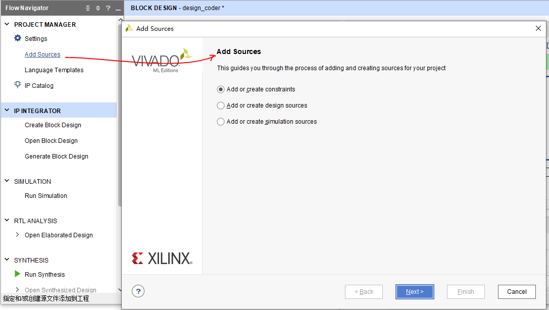
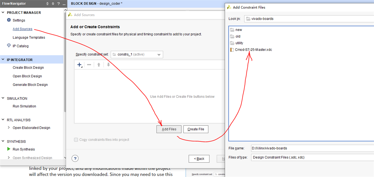
3.2 Add a Master XDC File to a Vivado Project

Download and extract digilent-xdc-master.zip and click the Add Sources button ,

image

imageimageimage

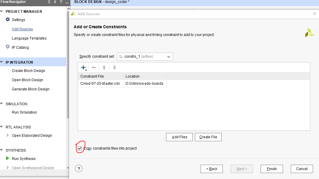
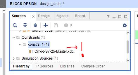
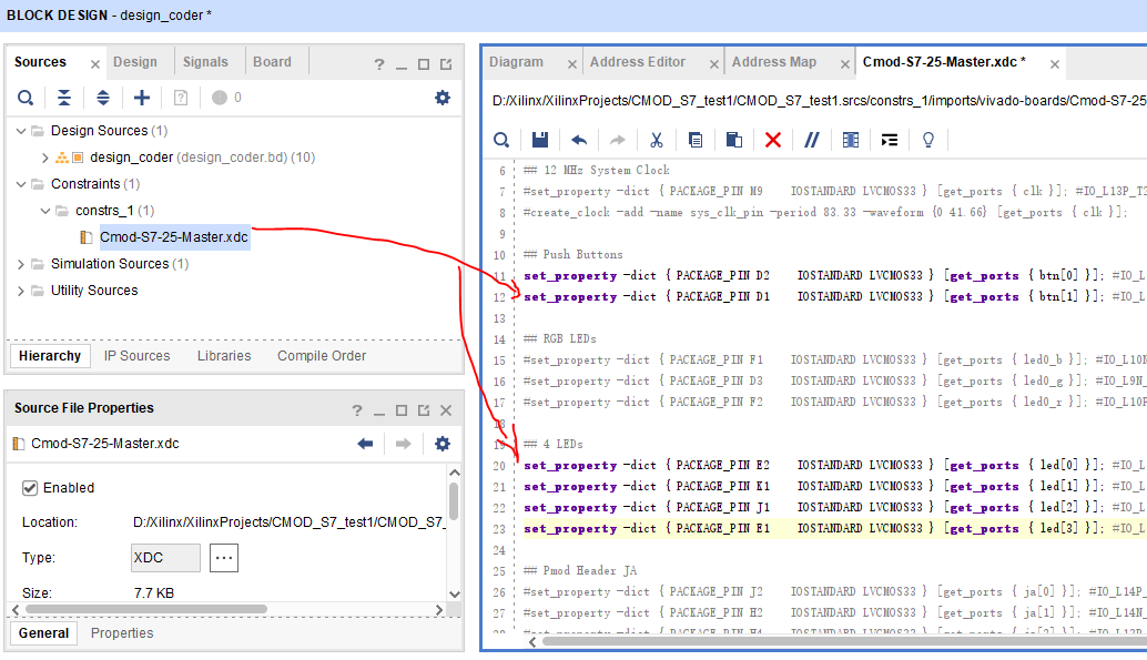
Un-comment the button constraints by removing the single leading '#' character in each line corresponding to the buttons in the XDC file will appear in the Sources tab.

image

Select the GPIO_0 external port that is connected to the AXI_GPIO_BUTTONS block. Change the name of the external interface to “btn” in the Properties pane.

image

image

Then Run Connection Automation again after setting the property of GPIOs.

image

image

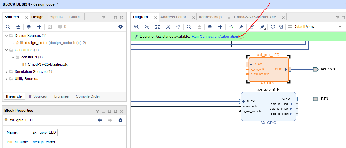
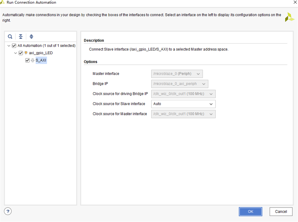
Address assignment is part of work, if not automated , it has to be made manually.

image

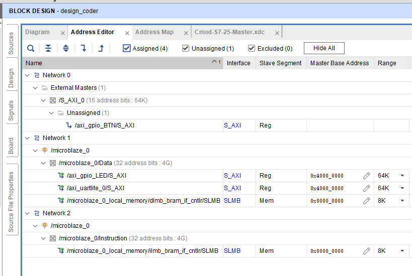
If Ok, the diagram shown without errors.

image

  • Sign in to reply
  • navadeepganeshu
    navadeepganeshu over 4 years ago

    Nice gear-up.

    Agree with the first line. I still find it hard to start from an empty main.c file.

    • Cancel
    • Vote Up 0 Vote Down
    • Sign in to reply
    • More
    • Cancel
element14 Community

element14 is the first online community specifically for engineers. Connect with your peers and get expert answers to your questions.

  • Members
  • Learn
  • Technologies
  • Challenges & Projects
  • Products
  • Store
  • About Us
  • Feedback & Support
  • FAQs
  • Terms of Use
  • Privacy Policy
  • Legal and Copyright Notices
  • Sitemap
  • Cookies

An Avnet Company © 2025 Premier Farnell Limited. All Rights Reserved.

Premier Farnell Ltd, registered in England and Wales (no 00876412), registered office: Farnell House, Forge Lane, Leeds LS12 2NE.

ICP 备案号 10220084.

Follow element14

  • X
  • Facebook
  • linkedin
  • YouTube