The project so far:
Blog One – In the Air Tonight Project Start
Blog Two– In the Air Tonight, unboxing, connecting and first try outs
Blog Three– In the Air Tonight, Design, Parameters and a Plan!
Blog Four– In the Air Tonight, The Build
Blog 5 - extending and stretch objectives <--- This one.
Extending and Stretch Objectives.
Going back through the original objectives as set, I am as satisfied as I am going to be in the absence of incorporating the Renesas sensors into my final build.
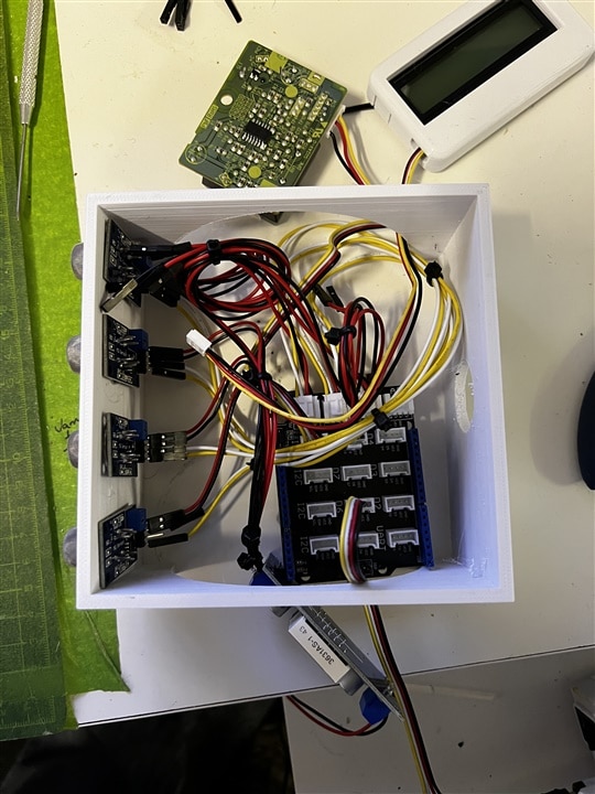
The array of sensors fit nicely within the enclosure. Which brings me to stretch objective no 1. Tidy up the power lines and seperate from the signal. To do this I will be creating a rear rail for the buck to mount on and the VCC/ GND lines to run right hand side / left hand side keeping the main enclosure area free.
Objective no 2. seperate the DO / AO lines and tidy up. To do this I am going to make up my own wiring harness once my grove latch free connectors arrive
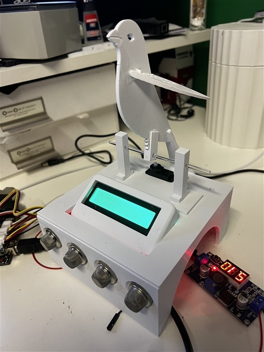
Conclusion, Pass or Fail?
The Renesas sensors are quite something. I was exciting to give the very high precious devices a try, as such things would be normally outside my budget for "projects". From the first box to getting up and running, it is clear that these are designed and built to a high standard and very much have industrial application in mind. This is where there is a gap for the home hobbyist / amateur or poker of things like myself. The gap i speak off is part software, part documentation and the near absence of any prior build or use that I could find by hobbyists.
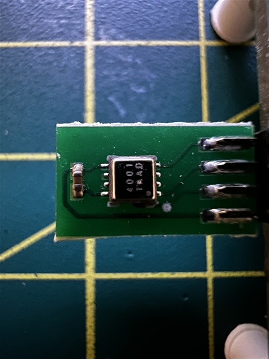
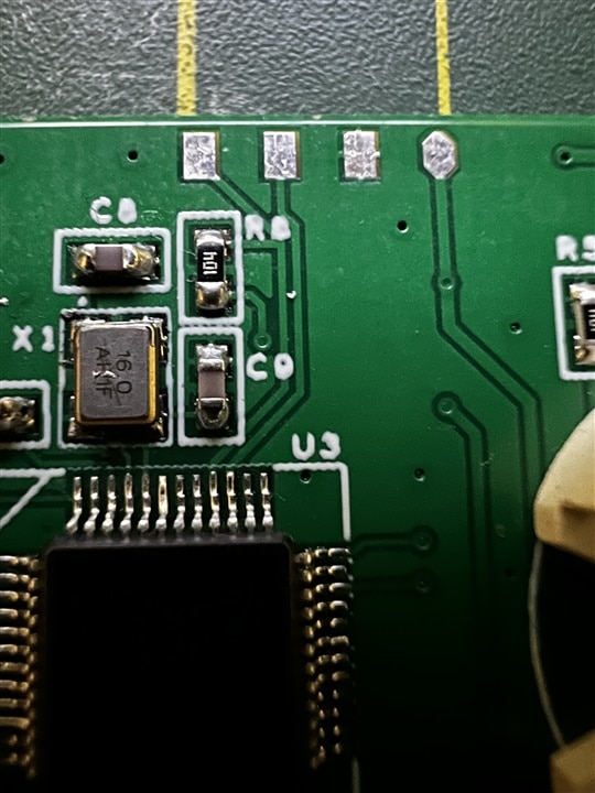
To appreciate quite how small this is, it is tiny. I sough to source a socket for the connectors used and whilst I have bought some, they are on their way from China at the moment and due sometime between end of September 22 and Feb 23
My attempts to create a breakout board for the breakout (similar to the Dupoint USB power connector), alas no cigar (it did not work despite being a strange idea). Having worked my way through options, I did note that on the back of the host board, these four pads. VCC right, ground pad and .. could they be SCL SDA? 3.3v logic on them ... and no cigar. My hopes of including the tem sensor were dashed.

Not to be beaten, despire the fact that it has me beat, I had little more success or joy with the AQ sensor. Again a ltiny little package, some incredible stats - up to a 10- year operational life? really? thats quite something.
Having only been able to successfully connect via my PC, following the last update and upgrading the FTDI drivers my own desktop PC refused to acknowledge the sensor, is it connected? have you installed the FTDI drivers .. zxyz missing. Hours, I have burnt hours on this to no avail. As an absolute last resort I tried using (shhhh, dont tell anyone) my work laptop. Installed, connected, worked a treat, until blocked as a previously unseen application.
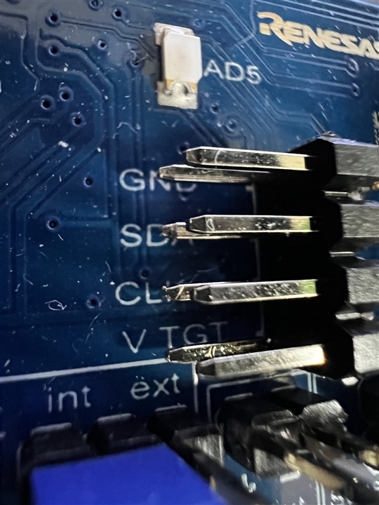
I had high hopes here, and my exitement went to disappointment, to frustration to why do you hate me Renesas sensors, we were going to be so good. You were going to be the crowning glory of my desk AQ box.
As I have not managed to successfully build either sensor into my final project, asides from being disappointed with myself I would like to offer the pair of sensors to anyone who applied to the competition who were not successful in being selected for the sponsored kit. I think this is OK to do and will confirm with E14 peoples, but if this is you and the postage is reasonable, I shall happily do so. Please drop me a message.
I now have a AQ sensor which ticks the boxes from my original specification, witht he exception of the sponsored kit / Renesas sensors so, pass for 90% of the project. Fail for the 10% that has 99% of the time burnt on it.
Other bits I had not included up to this point, BOM for building your own and the 3D files for priting your own bits and pieces.
Bill of materials
| Part name | No |
| Arduino Uno | 1 |
| Grove Sensor Shield V2 | 2 |
| MQ Sensors (usually MQ2,3,4,5,6,7,8,9,135) | - |
| Shinyei Optical Dust sensor PPD42NS-PPD42NJ | 1 |
| Grove 4 way connector - female header | 8 |
| 5v BUCK power convertor | 1 |
| Arduino Power supply | 1 |
| Low voltage servo (anaglog) | 1 |
| Low voltage audio sounder (grove) | 1 |
| RGD LCD 2x16 display | 1 |
| Consumerables | |
| White PLA Filament | 0.3kg |
| Superglue | |
| Clear 3mm modelling rod |
3D pieces to print
The attached zip file contains the STL files needed to print your own enclosure, no screws are required and 3-4 spot of super glue, thats it.
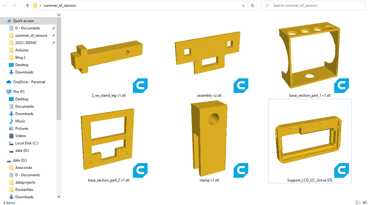
If you are reading this and want the design files let me know and I can happily post them.
My own attempt to draw a canary profile was closer to the dinosaurs that they are than the modern day cousins.
Canary / Budgie credit goes to Hey Jude over at instructables.com for his "Sonny the UV Budgie - an automata IoT bird who looks up online weather data from the Met Office API and announces the UV index for the day and the week ahead (in doing so, he flaps his wings automaton-style!)."
https://www.instructables.com/Build-a-UV-Level-Monitoring-Budgie-Using-IoT-and-W/ - a very cool build. YOu can grab the stl files for the budgie / canary here to print.

Top Comments