


Table of Contents
Introduction
Welcome again! This is my 7th blog in a series I am writing for the Summer of Sensors Design Challenge kindly sponsored by Element14 and in my case Vishay. The challenge is to make use of two selected sensor boards from Vishay’s SensorXplorer range. My project is an adaptive, smart bulb controller and in my last two blogs I successfully integrated both sensor boards to the ESP32 micro-controller and was able to obtain readings from them and print them to the console. Today we will be integrating the final component in this project – the smartbulb.
Selection of the Smartbulb
There are dozens of manufacturers of smart home accessories and almost all of them have a product range of smart bulbs available. As mentioned in an earlier blog I decided to go down the WiFi route as it suited my design needs and target audience the best. Browsing through Amazon you will see there are many really cheap, unbranded smart bulbs. Although these work perfectly well in general, I made the decision to go with a bigger brand as they would have better support, a wider product range and will probably be around for much longer.
I remembered reading an article a while back about TP-Link’s range of smart devices and it seemed to indicate that controlling the smart bulb was relatively straightforward using a defined set of JSON commands over a TCP connection. Since a lot of the other manufacturers seemed to have inaccessible or proprietary APIs, TP-Link seemed like a decent way to go and they also seemed to have a nice range of smart bulbs, plugs, switches and cameras. I particularly like the new range of smart spotlights that they have coming soon!
https://www.tp-link.com/uk/home-networking/smart-bulb/
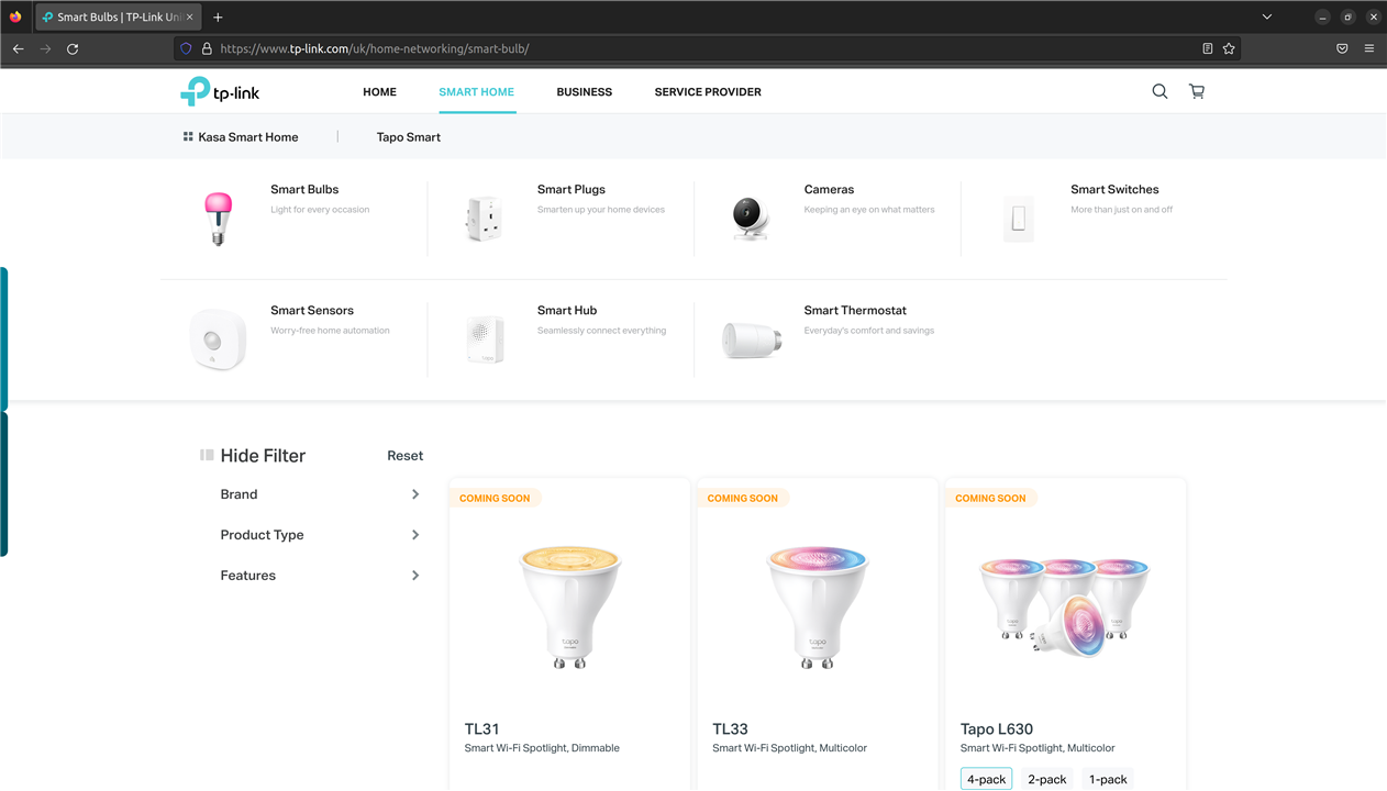
So having decided to go for a TP-Link smart bulb I immediately want to Amazon and bought the cheapest WiFi, colour, non-hub, smartbulb that TP-Link sold. At this stage I hadn’t realised that they had two product lines (“Kasa” and “Tapo”), so I bought the TapoL530B available here (more on the other product range later).
Reverse Engineering the Smart Bulb Protocol
In order to manually control the bulb from my own code running on the ESP32 I need to know what protocol and messages are used to set the colour, brightness and on/off state of the bulb. The easiest way to do this is to set the bulb up on my home WiFi, get the app installed on my phone, and then sniff the packets being sent to the bulb whilst I control it from my phone. This way I will see what protocol is used, how the messages are formatted and what the message payload consists of.
Wireshark is by far the most popular tool to capture network traffic, so after setting up the bulb on the WiFi I started capturing packets being sent to the IP address of the bulb whilst I played with the useful controls on the smart bulb app. This produced some captures like the following:
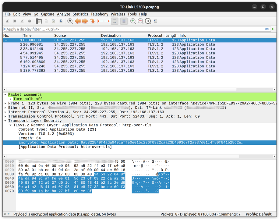
This is my packet capture when commanding the bulb off using the smartphone app. I did similar captures for turning the bulb on, setting the colour, and adjusting the brightness. However, this was not quite what I was hoping for! If you look carefully at this capture you will see the data is encrypted using TLSv1.2 and sent over TCP port 443 – basically HTTPS commands. In the article I read a few months ago I was lead to believe that the data used some noddy “encryption” and was sent over TCP port 9000 so would be easy to intercept.
At this stage, I did another bit of research into these TP-Link lightbulbs and discovered that they made two different ranges of smartbulbs. The newer range (“Tapo”) which is what I bought and their original range “Kasa”. It would appear that one of the new features of the newer “Tapo” range is that they use better encryption, and the older “Kasa” range is the one I read about using basic commands to TCP port 9000.
In theory this newer bulb would not be a showstopper because I could set up a MITM (man in the middle) attack by tunnelling all the HTTPS traffic through a proxy running on my laptop. This way I could install my own SSH certificate for the proxy and then I would be able to decode this encrypted payload. However, since the main emphasis of this project is to make good use of the Vishay sensors, I figured it would be better use of my time to purchase a smartbulb from the other range which would be easier to interface to.
Thanks to Amazon Prime, my TP-Link Kasa L130B smartbulb arrived the following day and I set it up on my WiFi network. Once I found the IP address of the bulb, I ran Wireshark to capture all traffic going to this new bulb using the Wireshark filter “dst host 192.168.1.171” and started controlling the bulb from the android app.
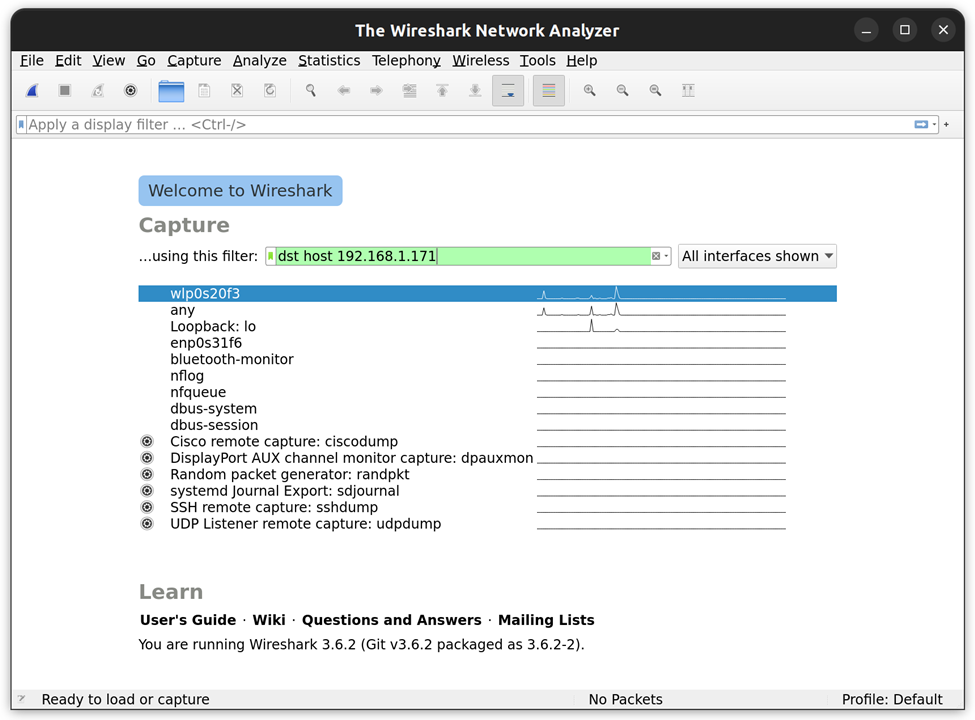
Before long packets started appearing and Wireshark, being the amazing tool it is, automatically detected the protocol as TPLINK-SMARTHOME and it even decrypted the packets for me and displayed the unencrypted payload – JSON formatted strings.
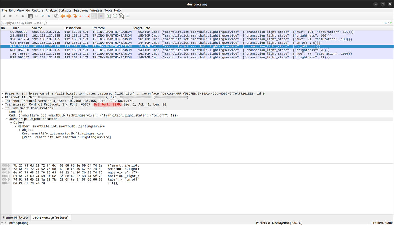
After turning the bulb on/off, setting the brightness and adjusting the colour, I now had all the information required to construct my own commands which would contain the following JSON strings:
{
    "smartlife.iot.smartbulb.lightingservice":
    {
        "transition_light_state":
        {
            "on_off": 1,
            "brightness": 100,
            "hue": 180,
            "saturation": 100
        }
    }
}
I knocked up a bit of python code to create an async client connection to the smartbulb on port 9000 and tried sending some commands to bulb. Sure enough, I was able to control the smart bulb successfully with the JSON string above (after encrypting with a basic autokey cypher).
I don’t want to spend too much time on this part of the project as it is not the main focus, but I thought I would include those few paragraphs as network diagnostics and reverse engineering protocols is very interesting. I am very grateful for some amazing documentation on this topic in this article which I found extremely useful for this project. Although the article is about a smart plug, the same process can be used for a smart bulb. If you are at all interested in reverse engineering some of your IoT devices, then that article is well worth a read.
Setting up WiFi on the ESP32
Having successfully controlled the smartbulb manually from a basic python script, I ditched the official android app on my phone – don’t need that anymore! The next step was to connect my ESP32 to the WiFi network. If you’ve done any work on the ESP32 family of micro-controllers, you will know how easy this is. To start with I scrolled through the list of example applications (just like we did a few weeks ago when creating the I2C application) until I found one which looked useful:
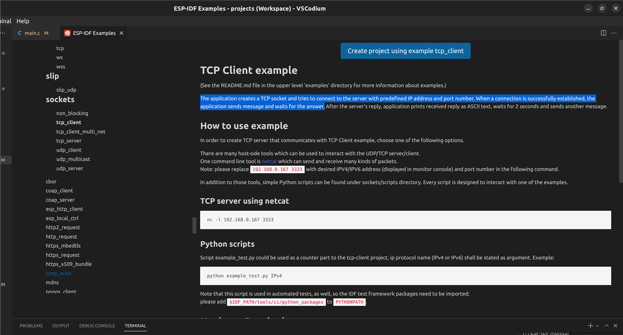
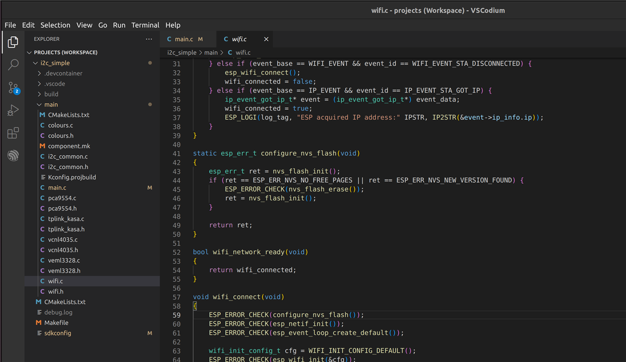
Looking through the source files for this example project it was very easy to see the functions required to set up the WiFi on the ESP32 and connect to an AP (access point). Going back to my original project, I added a new source/header file to handle the WiFi side of the system. The WiFi connection function was taken directly from the example project and is literally only 20 lines of code. I then added some event handlers to flash the RGB LED on the Vishay VEML3328 sensor board depending on the WiFi connection status.
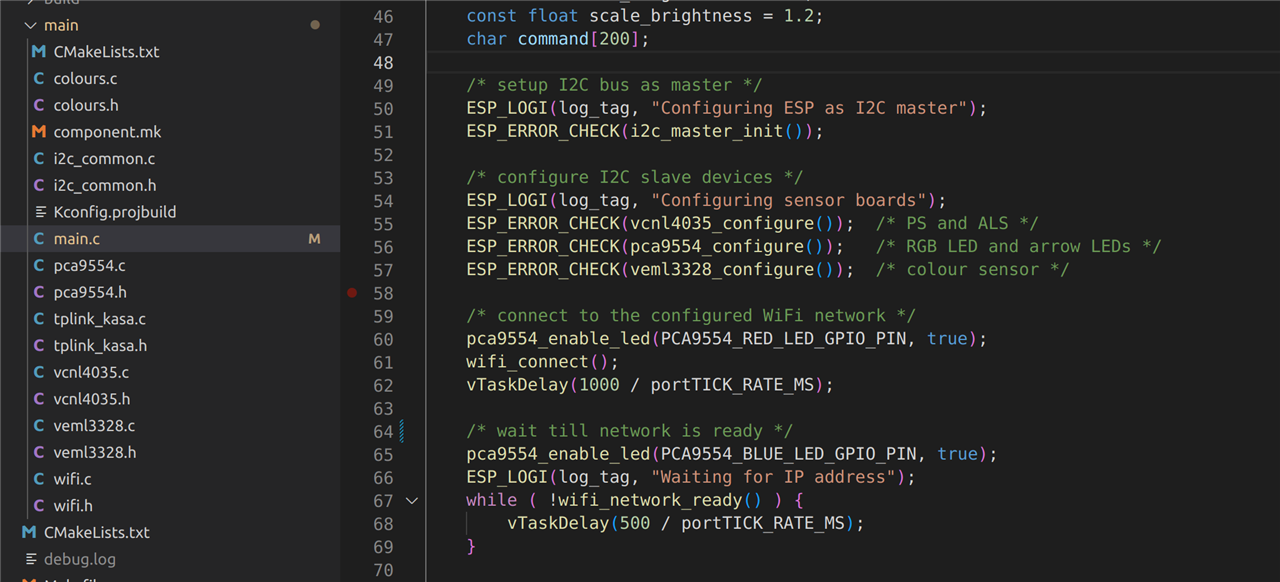
And then in the main application loop, after setting up the I2C sensors, I configure the WiFi and wait till the ESP32 has acquired an IP address before continuing:
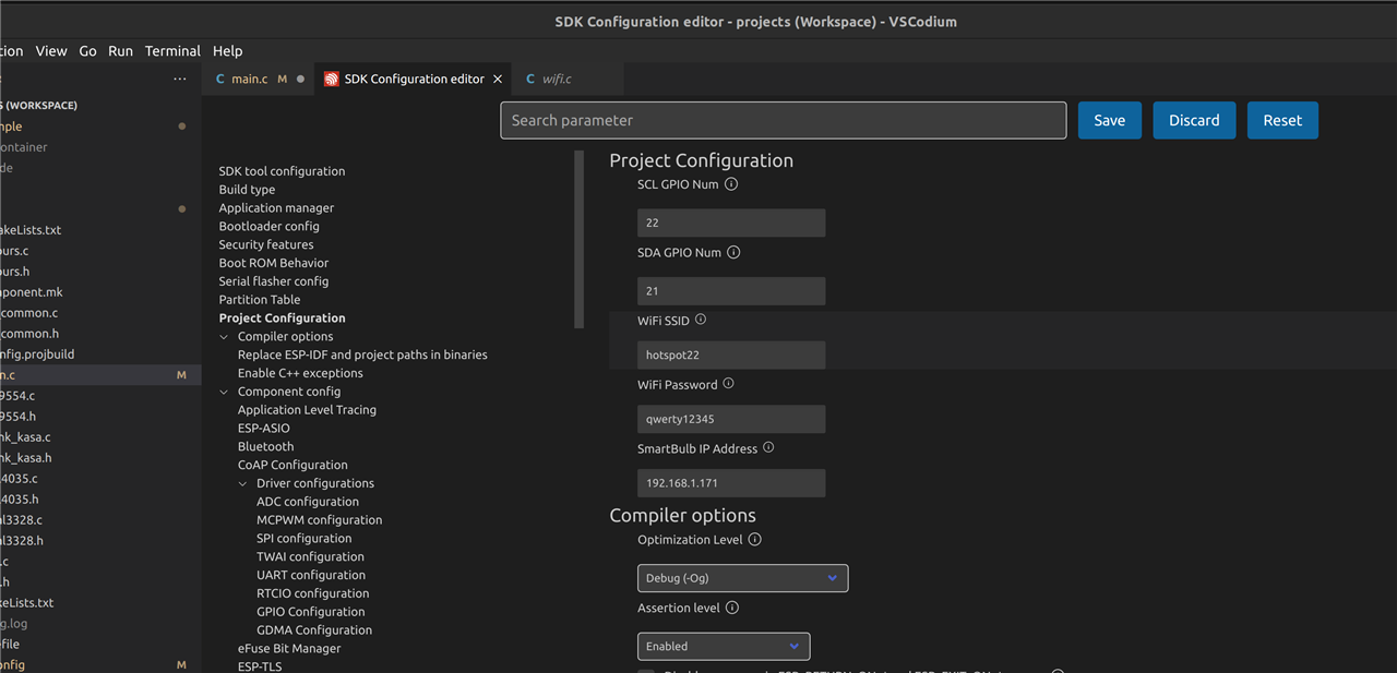
Instead of hardcoding the smartbulb IP address, WiFi SSID and WiFi password in the source code, I added it as a setting to the configuration page so it can be edited with the ESP Configuration Editor (part of the ESP VSCode extension):
And that is about everything needed for setting up a TCP client on the ESP32.
Communicating with the smartbulb from the ESP32
With the TCP client connection established to the smartbulb (on port 9000), the next stage is to build some JSON strings, encrypt them and send them. As is my habit, I like to keep every source file short/simple and having one purpose, so I created a new pair of files to handle the TP-Link/Kasa side of things – generating the JSON strings and encryption.
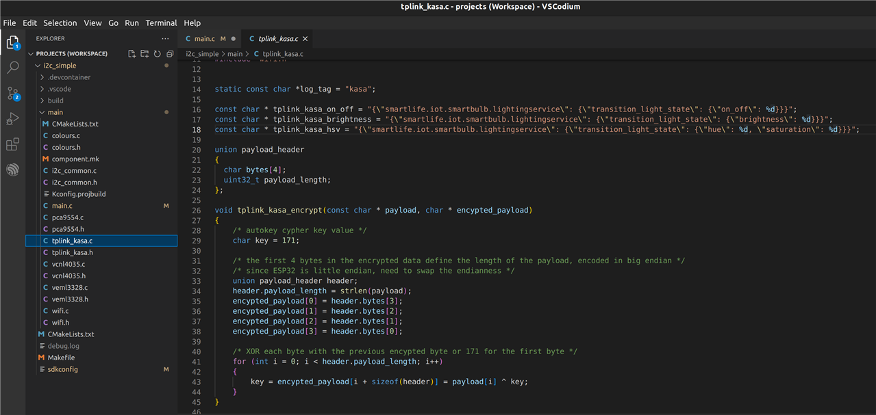
This snippet of code shows the very simple autokey cypher “encryption” method and the unencrypted JSON strings which will be used to control the smartbulb. Here you can see that I have split the JSON command into 3 separate commands so that I can control the on/off state, the brightness and the colour individually.
Using the sensor readings to control the smartbulb
The final step now is to use the readings from the two sensor boards (which we were able to read the other week over I2C) and use them to populate the values in the JSON string which I can then encrypt and send to the smartbulb. This is all handled from the main application loop in the main source file.
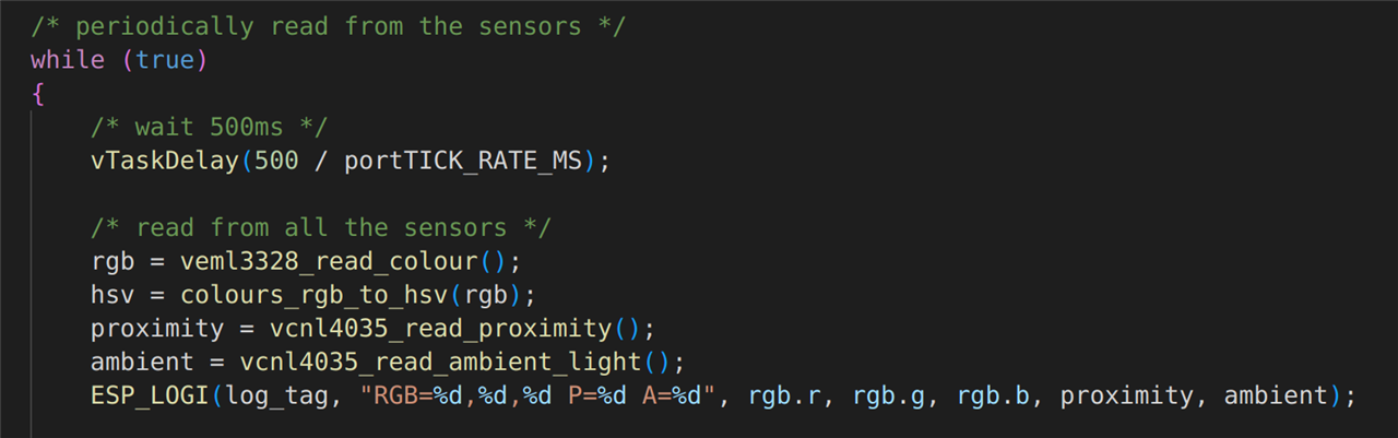
The first thing that happens once in the main loop is to read from all the sensors. Note, the colour sensor reports an RGB value, but the smartbulb requires HSV format, so the RGB value is converted after reading it from the Vishay VEML3328 sensor board. The values are all printed to the terminal for debugging purposes.
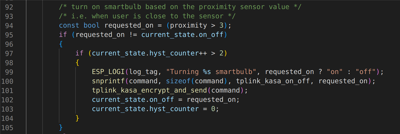
The first sensor which is processed is the proximity sensor. This sensor is used to detect when someone has sat down next to the lamp stand. If it detects an object close by, it will turn on the smartbulb. When that object (hopefully a person and not the cat) has moved away, the smartbulb will be commanded off. This is achieved by this next block of code in the main application loop:
The ambient light sensor is used to set the brightness of the bulb. This is achieved by the next block of code in the main application loop:
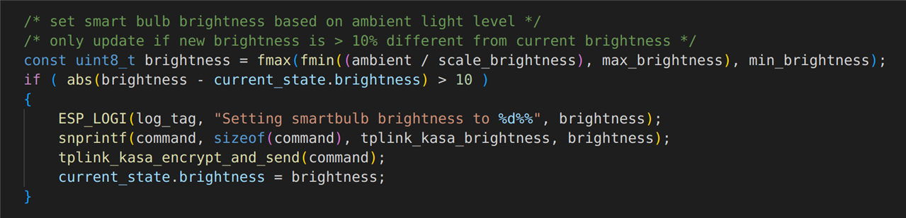
Note that the brightness of the bulb is only adjusted if a ±10% change in brightness is required. If the required brightness is right on the threshold of two values (e.g. oscillating between 50% and 51%), then very slight differences in the room lighting would keep triggering the bulb to change brightness. The reason for adding this 10% hysteresis is two-fold:
- Without the hysteresis, the bulb could flicker, and although a 1% change in brightness might not be noticeable it could easily cause headaches which is exactly the opposite to what we are trying to achieve here.
- The second reason is that continually adjusting for minor corrections in brightness (which will not even be noticed) will add to the network traffic, and yes, I know the packets are very small, but it is still unnecessary network traffic...and by the time you have several of these devices in you home it could get quite congested.
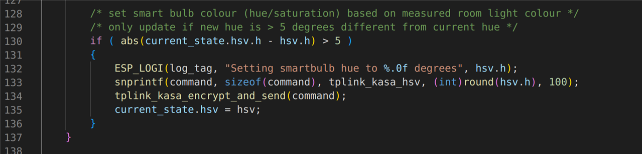
The colour sensor is used to measure the colour of the main lighting in the room. This is then used to set the colour of the bulb to match it. If the room has a nice warm yellow glow to it, then I don’t want my lamp in the corner to be a cold blue glow! This is achieved by the next block of code in the main application loop:
Testing it all out
All the code is now written, so after building, flashing and executing the code, the output can be viewed in the terminal:
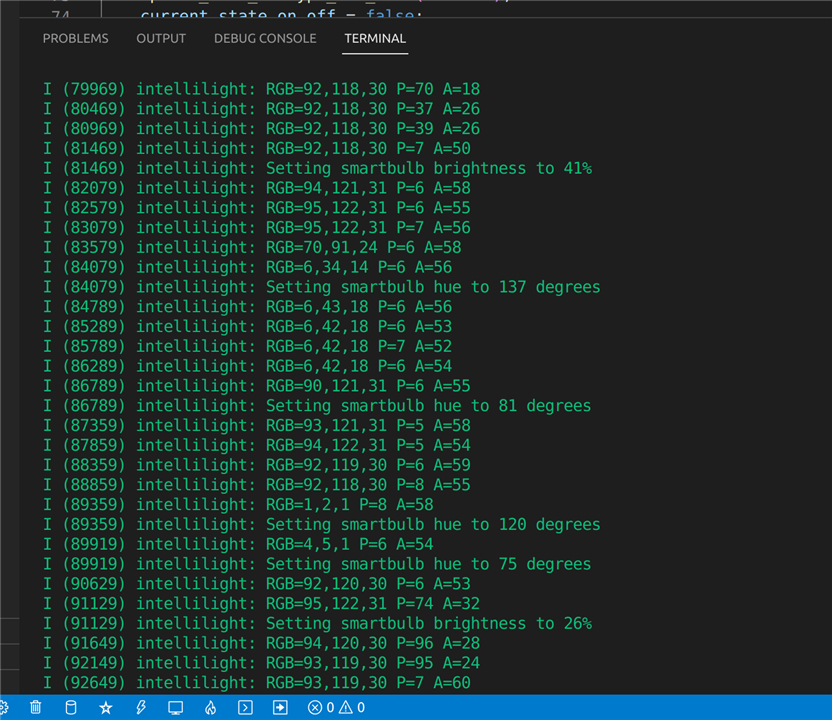
These results are really self-explanatory, but just to walk through one of them: if you look at the 5th line of debug, it is sending the encrypted JSON string to the smartbulb to set the brightness to 41%. The brightness is controlled by the ambient light sensor. On the line immediately before, the ambient light level was read as 50 whereas the previous reads were 26, so the ambient light level has increased (because I turned the room lights on) and therefore it is adjusting the brightness of the smartbulb accordingly.
Same explanation for the next command (setting the hue to 137 degrees). The previous line of debug indicates that the RGB value coming from the colour sensor changed from “70,91,24” to “6,34,14” hence the colour of the bulb is being adjusted accordingly.
Coming Next…
So all the sensors are working, the smartbulb is working, the WiFi is working and all the communications in-between are working and behaving well. I need to perform some calibration of the sensors to make sure I’ve got the correct trigger level for the proximity sensor and to make sure I’ve got the right threshold and scale for the brightness etc., but on the whole it is all responding correctly. So, the next stage of the project is to box it all up! If you are interested in 3D printing, CAD models, soldering, or hot glue guns, then please stay tuned for my next blog. As always, many thanks for taking the time to read this blog, please keep the comments coming and I’ll see you in a few days’ time.
| Previous Blog (Part 6) | Next Blog (Part 8) |
-

dougw
-
Cancel
-
Vote Up
0
Vote Down
-
-
Sign in to reply
-
More
-
Cancel
-

osjef
in reply to dougw
-
Cancel
-
Vote Up
0
Vote Down
-
-
Sign in to reply
-
More
-
Cancel
Comment-

osjef
in reply to dougw
-
Cancel
-
Vote Up
0
Vote Down
-
-
Sign in to reply
-
More
-
Cancel
Children