


BLOG# 2 - BPM Uno – Research & Experimentation A Patient Beats Per Minute Heart Rate Monitor This blog is part of a blog series for the Summer of Sensors -- Under Pressure Design Challenge.
Since I have not used most of the components in the kit before I will need to research and experiment with the MIKROE-1581-Arduino Uno Shield and MIKROE-2000-Heart Rate Click and the Arduino Uno SMD MCU. This blog describes my research and my experimentation on the components of the kit.
Table of Contents
Experimenting with Kit components
In this section, I will be describing the research and notes I took while learning about these components
Arduino Uno SMD
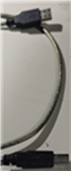 Programming the board was a matter of configuring it in the Arduino IDE for the “Arduino Uno”.
- Connecting the a special USB cable that does not come in the Uno package and is sold separately Arduino UNO USB Data Sync Cable
- Loading in the Blink example
- Then, Flashing it to the UNO SMD board.
- And now I have my Firmware development environment setup to use the Uno with the components from the kit.
MIKROE-1581 Arduino Uno Shield
- I will need to solder the header pins onto the Shield, to form a solid connection for the Shield. In the meantime I stacked the shield onto my Grove Base Shield from my Grove Starter kit and then stacked that onto the UNO SMD. I used the supplied headers that come with the shield and placed one side of each header into the Grove headers and the other side through the shield PCB corresponding holes.
• I then attached the MikroE Relay click that I own on the shields mikroBUS 1 header
• I then used the following Arduino Sketch
const int RelayPin = 6;
const int ledPin = 13;
void setup() {
pinMode(RelayPin,OUTPUT);
pinMode(ledPin,OUTPUT);
digitalWrite(RelayPin,LOW);
digitalWrite(ledPin,LOW);
}
void loop() {
digitalWrite(RelayPin,HIGH);
digitalWrite(ledPin,HIGH);
delay(2000);
digitalWrite(RelayPin,LOW);
digitalWrite(ledPin,LOW);
delay(2000);
}
• I had to get a good connection on the Shield (by pinching the headers) but It worked.
• I could hear the relay clicking
 MIKROE-2000 Heart Rate Click
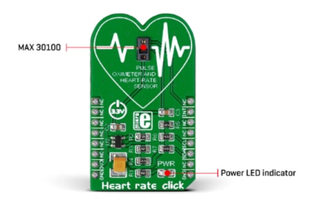
Courtesy of the product page on the MikroE website.
- This Click carries the Maxim MAX30100 integrated pulse oximetry and heart rate sensor. I’m more interested in its Heart Rate capabilities rather than the pulse oximetry, since my idea is to implement a BPM monitor. The Pulse Oximetry is an added bonus. The MAX30100, is manufactured by Maxim Integrated and the company has stopped the production of the MAX30100 in favor of MAX30101 and MAX30102. MikroE, also has click boards with these sensors on them. For example the Heart Rate 4 Click, carries the MAX30101.
- The Challenge kit also includes the Oximeter 5 Click, which carries the MAX30102 sensor. The MAX30102 is a complete pulse oximetry and heart-rate sensor system solution. Good to know. I will have to experiment with it and compare capabilities.
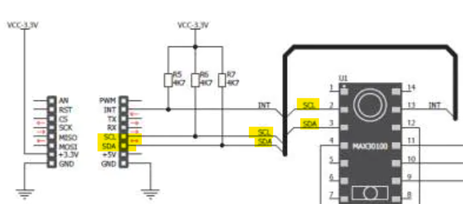
- The MAX30100 is an optical sensor that takes readings from red & infrared LEDs. The sensor then measures the absorbance of pulsing blood through a photodetector. This particular LED color combination is optimized for reading the data through a fingertip. The signal is processed by a low-noise analog signal processing unit. A I2C interface is used to communicate with the target MCU. The only required connection to the sensor is the I2C bus (SDA, SCL lines, pulled up).
- The MAX30100 SDA, SCL lines are attached to the pins on theMIKROE-2000 Heart Rate click. A programmable INT pin is also available.
- The MAX30100 is an optical sensor that takes readings from red & infrared LEDs. The sensor then measures the absorbance of pulsing blood through a photodetector. This particular LED color combination is optimized for reading the data through a fingertip. The signal is processed by a low-noise analog signal processing unit. A I2C interface is used to communicate with the target MCU. The only required connection to the sensor is the I2C bus (SDA, SCL lines, pulled up).
- The MAX30100 SDA, SCL lines are attached to the pins on theMIKROE-2000 Heart Rate click. A programmable INT pin is also available
Courtesy of MikroE product page on the Mouser web site
- MIKROE-2000 uses a 3.3V power supply.
- This is a diagram of the Heart Rate click enabled pins on the mikroBUS socket
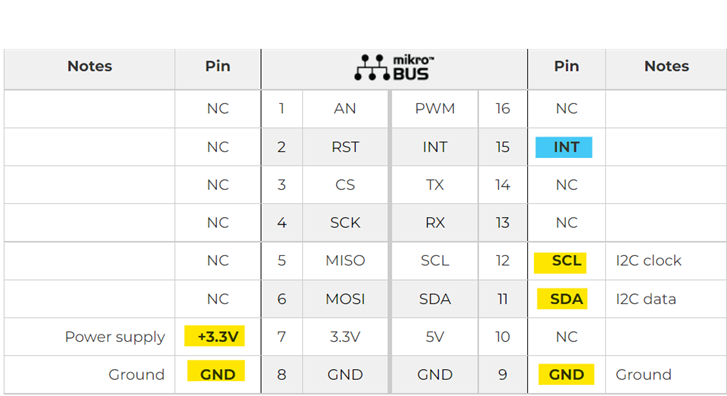
Courtesy of the product page on the MikrroE website.
- The MikroE product page, gives an excellent description of How does it work? I’d like to ponder some point as follows
- It features an advanced oximeter and heart rate monitoring sensor
- It is enough to place an index finger on a top of the sensor to get both of the heart rate and blood oxygen saturation via the I2C interface.
- Ensure that no ambient light or 50/60Hz hum is interfering with the readings.
- Low Power Consumption: it is possible to put the device into the Standby mode, where it consumes a very low amount of power.
- An ideal solution for various heart-rate applications, as well as the development of new algorithms for reading blood parameters based on the red and infra-red absorbance properties of the human body, mainly for the heart rate (HR). I can’t wait to compare the reading from my other Heart Rate Sensors compared to the MAX10100
- This sensor features two integrated LEDs with the RED and IR LEDs, used to emit the respective wavelengths.
- There is also a temperature sensor, which can be utilized to compensate for the changes in the environment and to calibrate the measurements.
- To improve the measurements, the MAX30100 sensor employs a temperature sensor. This is a reasonably precise temperature sensor, which measures the die temperature. This sensor can be read from its data register. It will be interested to capture this data during readings?
- The MAX30100 sensor has the FIFO buffer, 16 words deep. The FIFO buffer stores the measured values and it can generate an interrupt when the buffer is full, allowing the host MCU to perform other tasks, while the data is collected by the sensor.
- The interrupt line from the sensor is also routed to the mikroBUS
 INT pin. By setting the appropriate INT register, the interrupt can be generated and enabled for 5 different sources: power ready, SpO2 ready, HR ready, temp ready, FIFO full. Each interrupt is reported by the status bit in the interrupt status register and by pulling the INT line to a LOW logic state.
- The MikroE product page, also has a “Software Support” section, that describes the library offered on the Libstock page, as well as a demo application (example), developed using MikroElektronika compilers and mikroSDK. I might come back to this topic when I have more time, but in the past, I found it easier to get examples for the specific MCU platform. For example, for the Relay Click it was as simple as sending a digital write to the A0 pin on the click. I didn’t’ need a library to do it, I just found advice on the Internet. In all honesty, I chose not to follow this route, for several reasons (Arduino IDE support and examples) and decided to try to find an Arduino supported library and examples that I could experiment in the Arduino IDE. I eventually found a library on a GitHuB repo (Arduino-MAX30100), that supported the MAX30100.
- The Arduino UNO r3, Mikroelektronika Heart rate click (https://shop.mikroe.com/heart-rate-click) is listed in the repo as a “Tested device”
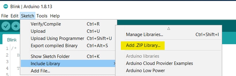
- I cloned the library to a zip file and using the Arduino IDE included it by adding the zip file with the “Include Library” tool as described below.
- The library also includes 4 useful examples that I tried out. The included examples show how to use the PulseOximeter class:
- MAX30100_Minimal: a minimal example that dumps human-readable results via serial
- MAX30100_Debug: used in conjunction with the Processing pde "rolling_graph" (extras folder), to show the sampled data at various processing stages
- MAX30100_RawData: demonstrates how to access raw data from the sensor
- MAX30100_Tester: this sketch helps to find out potential issues with the sensor
- CONCLUSIONS
- This library is just what I needed to implement my idea with the MAX10100 Equipped Heart Rate Click
- All the test and the examples worked great and were helpful in understanding the library and how to develop firmware for the MAX10100 enabled MikroE-2000
Getting BPM’s
My research leads me to this VIDEO https://www.youtube.com/watch?v=5WI2lxr9CVE
And a project by the same person https://www.electroniclinic.com/max30100-pulse-oximeter-arduino-code-circuit-and-programming/
This project uses the MAX10100 described above and I’m hoping I can use some of the logic to implement my idea.
Summary & Conclusions
- My research proved really gratifying and I am real confident now that I will be able to implement my idea.
- I was able to:
- Get a firmware development environment setup to use the Arduino UNO SMD as a base MCU
- I was able to find an Arduino Supported library for the MAX10100 sensor
- I was able to gain a thorough understanding of the MAX10100 sensor and the Heart Rate 2000 click.
- I had already done a circuit using the SSD1306 I2C OLED Display, so I’m pretty confident that the Connects and test will work on it using my firmware from the prototype presented in bolg#1 of the challenge. It uses I2C so hopefully in theory it will coexist with the Heart Rate Click.
- If not then I can use the Grove Backlight LCD from my starter kit with the Grove Base Shield.
- I found a BPM example using the MAX10100 Arduino Library.
- The headers of the MikroE Uno shield need to be soldered on!! I’m not very steady handed and I’m a little worried about the possibilities of ruining the board. I’m not sure why companies offer a solution to stack an interface without shipping the product without the prime reason for it’s use the header pins soldered on? OK, enough of my rant. Suck it up and do it!!!
-

DAB
-
Cancel
-
Vote Up
0
Vote Down
-
-
Sign in to reply
-
More
-
Cancel
Comment-

DAB
-
Cancel
-
Vote Up
0
Vote Down
-
-
Sign in to reply
-
More
-
Cancel
Children