


In this blog, I'm writing about the software that controls Rullit
1. Introduction
Rullit will follow a simple path, shown in picture
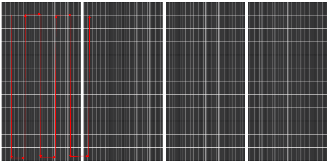
The goals of the control software is to
- constantly monitor the limit switches, to prevent the robot from falling from the PV modules
- calculate the proper PWM values to drive the robot along the above-mentioned path
2. Safety controls
As already mentioned, it is very important to constantly monitor the limit switches and immediately stop the motors when the PV module edge has been reached. To achieve this goal, the software will be implemented as a state machine, meaning that there will be no blocking functions (i.e. functions that takes of lot of time). In this way, the loop() function will be called as fast as possible
3. Position control
The math to control the position of the robot is quite simple
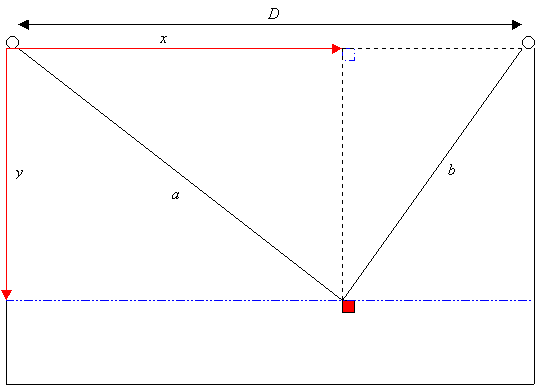
With the Pythagorean theorem, we can write

and, inverting the formulas,
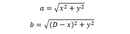
According to the formula, the total width of PV modules to clean (D) must be known. In this first version I am going to use this simple approach. In next release, I would like to implement an algorithm that does not need to know the value of D, so that I can plug-and-play Rullit on any PV plant and have the modules cleaned.
To move Rullit to position (x, y), we need to wind and unwind thread from the left and right pulleys so that lengths match the value calculated with the above mentioned formulas. This is the theory. To make a real implementation of this algorithm, we need to take into account two important factors
- at low PWM values, motor may stall
- due to construction tolerances, two motors may not run exactly at the same speed even when controlled with the same PWM signal
Regarding point n.2, I am evaluating whether to add a feedback mechanism based on a gear wheel and a limit switch. However, this application does not require an high precision in position control. For this reason, I am not going to implement this "encoder" at this stage.
Regarding point n.1, let's first have a look at how I am going to calculate PWM values. The software will implement a control loop that, given the maximum speed the thread can be winded, calculates for each motor a PWM value so that thread lengths allows the robot to move to next position in the path.
To make this calculation, it's useful to define some constants:
- The wind and unwind speed (in mm/s) is given by
#define MOTOR_SPEED_RPM 30.0
#define PULLEY_RADIUS_MM 16.0
#define SECONDS_PER_MINUTE 60.0
#define THREAD_SPEED_MM_S ((MOTOR_SPEED_RPM * PULLEY_RADIUS_MM * 2 * PI) / SECONDS_PER_MINUTE)
- The maximum distance the robot can be moved during a control cycle is given by
#define CYCLE_TIME_MS 100.0
#define CYCLE_TIME_S (CYCLE_TIME_MS / 1000.0)
#define SAFETY_MARGIN 0
#define STEP_MM (THREAD_SPEED_MM_S * CYCLE_TIME_S * (1.0 - SAFETY_MARGIN))
- The horizontal distance robot has to move to right when I reach the top or the bottom of PV modules is 20 cm (paint roller is about 23 cm)
#define RIGHT_STEP_MM 200
- the plant total width is 11 meters
#define WIDTH_MM 11000.0
Assuming the aLength and bLength store the current a and b thread length, the PWM to move to new position (x, y) are calculated as
float a = sqrt(x*x + y*y);
float b = sqrt((WIDTH_MM-x)*(WIDTH_MM-x) + y*y);

float aDelta = a - aLength;
float bDelta = b - bLength;

float leftPerc = (aDelta * 100.0 / CYCLE_TIME_S) / THREAD_SPEED_MM_S;
float rightPerc = (bDelta * 100.0 / CYCLE_TIME_S) / THREAD_SPEED_MM_S;
where leftPerc and rightPerc are the PWM values (from -100 to 100%) for left and right motor. Value sign determines the direction of rotation
When Rullit is close to the left edge, rightPerc is close to 0 (similarly, when the robot is close to the right edge, leftPerc is close to 0). This leads to motor stall. A simple workaround is not to move the motor until the calculate PWM value is above a certain threshold. If the PWM value is below the threshold, I do not update the aLength or bLength variables, so that the distance between the current thread length and the expected thread length increases. This is the new code
float a = sqrt(x*x + y*y);
float b = sqrt((WIDTH_MM-x)*(WIDTH_MM-x) + y*y);

float aDelta = a - aLength;
float bDelta = b - bLength;

float leftPerc = (aDelta * 100.0 / CYCLE_TIME_S) / THREAD_SPEED_MM_S;
float rightPerc = (bDelta * 100.0 / CYCLE_TIME_S) / THREAD_SPEED_MM_S;

leftOnMs = CYCLE_TIME_MS;
if (leftPerc < PERC_LOW_LIMIT)
{
  leftPerc = 0;
}

rightOnMs = CYCLE_TIME_MS;
if (rightPerc < PERC_LOW_LIMIT)
{
  rightPerc = 0;
}

if (leftPerc > 0)
  aLength = a;

if (rightPerc > 0)
  bLength = b;
PERC_LOW_LIMIT is the minimum PWM value we want to drive motor with. I set the threshold to 50%
#define PERC_LOW_LIMIT 50
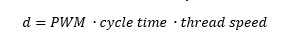
Note that, according to the code, the PWM value is given by the formula
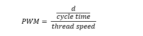
which means that the thread winded or winded during a control cycle is given by
With the above-mentioned values, the distance that leads to a 50% PWM is 2.5 mm, which is neglectable in comparison with other errors. One major source of positioning are the changes in bobbin radius due to the rope being winded and unwinded. To compensate for this, I implemented the calculation of the radius based on estimated a and b lengths. Given the minimum and maximum bobbin radius and the total length of the rope, the actual diameter is calculated as
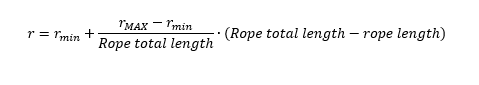
This is the radius that is used in above formulas
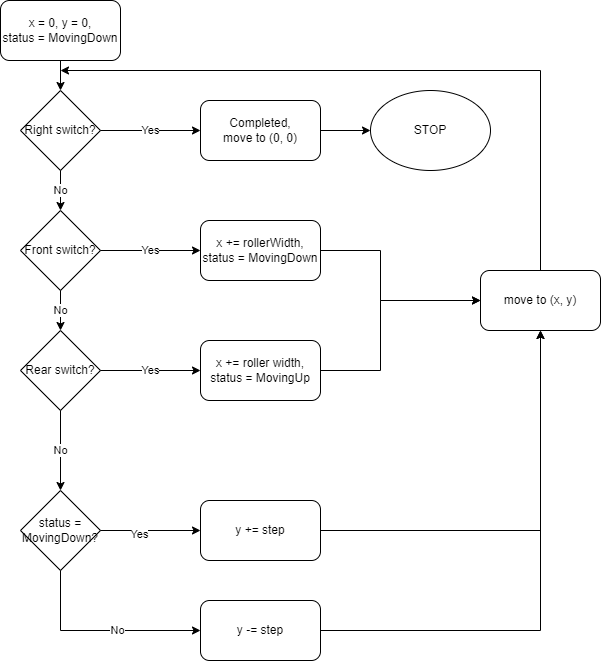
The application logic is streamlined in below flowchart
4. Limit switch
I created a small class that encapsulates the logic for handling all the issues related to limit switches (namely, debouncing). The class has two methods (init() and update()) and two accessors to get the current debounced state of the limit switch. The update() takes care of debouncing the input signal and return to the caller a stable input state
bool LimitSwitch::update()
{
  int status = digitalRead(_pin);
  if (status != _status)
  {
    if (_changeMs = 0)
    {
      _changeMs = millis();
    }

    unsigned long delta = millis() - _changeMs;
    if (delta > DEBOUNCE_MS)
      _status = status;
  }
  else
  {
    _changeMs = 0;
  }
}
5. Water dispenser
All the logic that controls the solenoid valve that let water flow toward the roller is encapsulated in the class Dispenser. As usual, the class has two methods (init() and update()). The update is called periodically to let the class decide whether to open or close the solenoid valve.
Currently I implemented two control algorithms
- the first one uses fixed timeouts (the valve is opened for a fixed amount of time every x seconds)
- the second one reads rollers humidity and open the valve when the roller is too dry
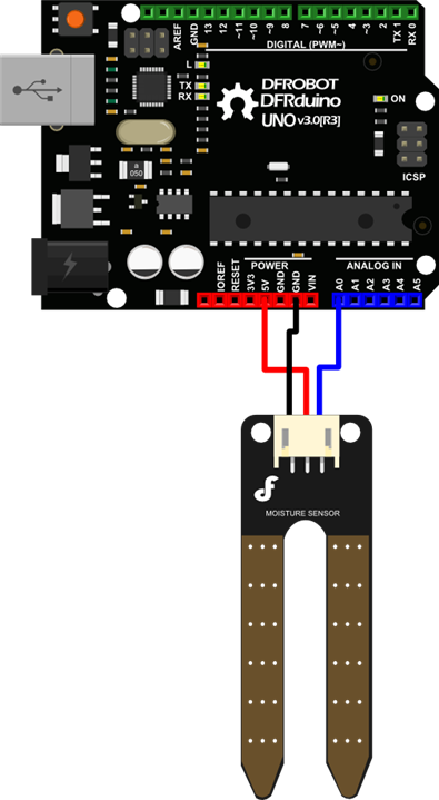
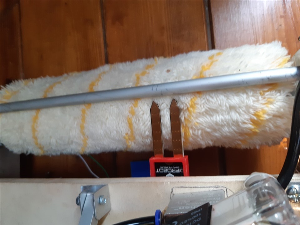
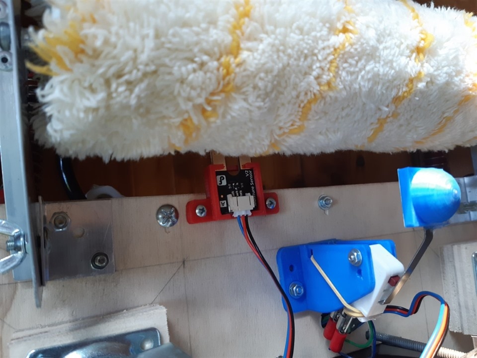
The second algorithm uses a moisture sensor made by DFRobot. This is a quite easy resistive sensor, with a NPN transistor to amplify the voltage drop between the sensor probes.
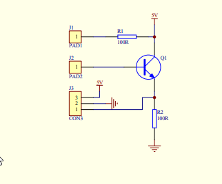
Voltage drop is proportional to resistance between the pads, which, in turn, is proportional to the level of humidity of the roller. DFRobot reports the following typical values for soil humidity
- 0 - 300: dry soil
- 300 - 700: humid soil
- 700 - 950: in water
After some tests, I selected a threshold of 500. Here is the flowchart of the dispenser's control logic
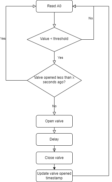
Sensor has three pins: Vcc, GND and an analogue output. Analogue output is connected to Arduino Uno's A0 pin
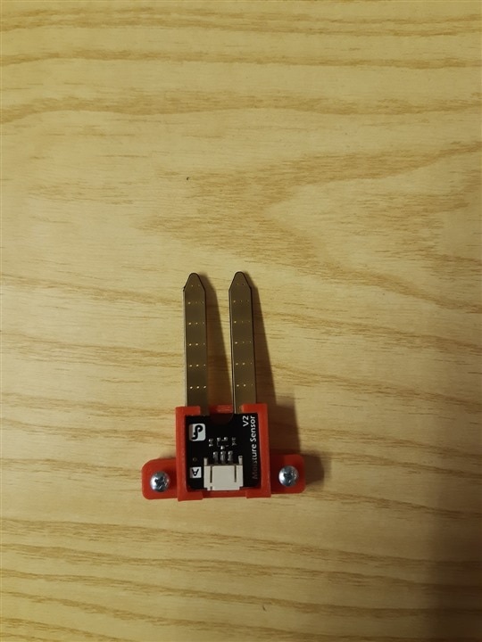
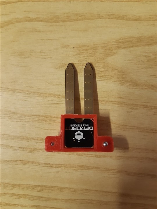
Here are some pictures of the moisture sensor installed on the chassis
|
Prev: Building the robot |
Next: The software (update) |


