element14 Community
element14 Community
    Register Log In
  • Site
  • Search
  • Log In Register
  • Community Hub
    Community Hub
    • What's New on element14
    • Feedback and Support
    • Benefits of Membership
    • Personal Blogs
    • Members Area
    • Achievement Levels
  • Learn
    Learn
    • Ask an Expert
    • eBooks
    • element14 presents
    • Learning Center
    • Tech Spotlight
    • STEM Academy
    • Webinars, Training and Events
    • Learning Groups
  • Technologies
    Technologies
    • 3D Printing
    • FPGA
    • Industrial Automation
    • Internet of Things
    • Power & Energy
    • Sensors
    • Technology Groups
  • Challenges & Projects
    Challenges & Projects
    • Design Challenges
    • element14 presents Projects
    • Project14
    • Arduino Projects
    • Raspberry Pi Projects
    • Project Groups
  • Products
    Products
    • Arduino
    • Avnet & Tria Boards Community
    • Dev Tools
    • Manufacturers
    • Multicomp Pro
    • Product Groups
    • Raspberry Pi
    • RoadTests & Reviews
  • About Us
  • Store
    Store
    • Visit Your Store
    • Choose another store...
      • Europe
      •  Austria (German)
      •  Belgium (Dutch, French)
      •  Bulgaria (Bulgarian)
      •  Czech Republic (Czech)
      •  Denmark (Danish)
      •  Estonia (Estonian)
      •  Finland (Finnish)
      •  France (French)
      •  Germany (German)
      •  Hungary (Hungarian)
      •  Ireland
      •  Israel
      •  Italy (Italian)
      •  Latvia (Latvian)
      •  
      •  Lithuania (Lithuanian)
      •  Netherlands (Dutch)
      •  Norway (Norwegian)
      •  Poland (Polish)
      •  Portugal (Portuguese)
      •  Romania (Romanian)
      •  Russia (Russian)
      •  Slovakia (Slovak)
      •  Slovenia (Slovenian)
      •  Spain (Spanish)
      •  Sweden (Swedish)
      •  Switzerland(German, French)
      •  Turkey (Turkish)
      •  United Kingdom
      • Asia Pacific
      •  Australia
      •  China
      •  Hong Kong
      •  India
      •  Korea (Korean)
      •  Malaysia
      •  New Zealand
      •  Philippines
      •  Singapore
      •  Taiwan
      •  Thailand (Thai)
      • Americas
      •  Brazil (Portuguese)
      •  Canada
      •  Mexico (Spanish)
      •  United States
      Can't find the country/region you're looking for? Visit our export site or find a local distributor.
  • Translate
  • Profile
  • Settings
Upcycle It
  • Challenges & Projects
  • Design Challenges
  • Upcycle It
  • More
  • Cancel
Upcycle It
Blog Upcycle It - Washing Machine Hydroponic Grower - #5 Circuit Design
  • Blog
  • Forum
  • Documents
  • Polls
  • Files
  • Events
  • Mentions
  • Sub-Groups
  • Tags
  • More
  • Cancel
  • New
  • Share
  • More
  • Cancel
Group Actions
  • Group RSS
  • More
  • Cancel
Engagement
  • Author Author: nandohila
  • Date Created: 5 May 2017 3:02 AM Date Created
  • Views 546 views
  • Likes 3 likes
  • Comments 3 comments
  • hydroponics
  • arduino programing
  • upcycle_it
  • fritzing
  • arduino ide
  • upcycled_hydroponics
  • washing_machine
  • intel edison
Related
Recommended

Upcycle It - Washing Machine Hydroponic Grower - #5 Circuit Design

nandohila
nandohila
5 May 2017

Most of the heavy work was complete, it is still missing the water tank and pump connection thought.


Now is time to describe how the system will work and establish bases to start sketching the program.


We will start with a very basic design to have the rotary growing system going and as we go we can implement more sophisticated functions or add more sensors and controls.


Below is the block diagram showing Inputs and Outputs connected to the Intel Edison Arduino Board and a brief description of each I/O.
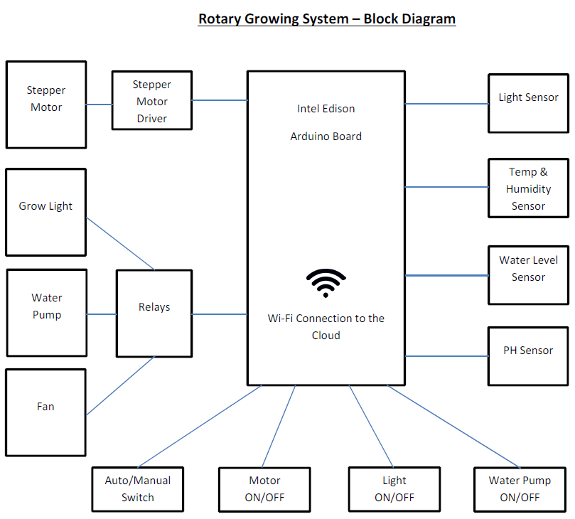
image


OUTPUTS


     Stepper Motor turns the drum continuously at an RPM set through the remote dashboard;

     Grow Light switches On/Off at times set through the remote dashboard;

     Water Pump switches On/Off at a frequency set through the remote dashboard;

     Fan switches On/Off depending on the temperature and humidity readings.


INPUTS


Sensors:

Light Sensor records the grow light intensity and sets an alarm if the Grow Light is set on but there is no reading;

Temperature Sensor records the temperature inside the drum and switches the Fan on if temperature is above set limit;

Humidity Sensor records the humidity inside the drum and switches the Fan on if humidity is above set limit;

Water Level Sensor sets an alarm if the water level is lower than the set limit;

PH Sensor sets an alarm if PH reading is out of the set limits.


Switches:

Auto/Manual Switch gives manual access to the next switches bypassing the programmed instructions;

Motor Switch turns drum motor On/Off

Light Switch turns grow light On/Off

Water Pump Switch turns water pump On/Off


Using Fritzing we created the sketch below showing the actual connections to the Intel Edison Board.


image


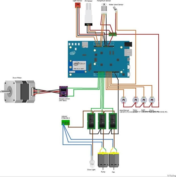
Having the basis to start programming and connecting the components to the board we will use the Arduino IDE to program the board. The programming instructions will be presented on the next posts.

  • Sign in to reply

Top Comments

  • DAB
    DAB over 8 years ago +2
    I agree with Scott. Usually you do not want to exceed more than about 20mA on the outputs. Use a driver transistor or a MOS FET and you can do the job. DAB
  • mcb1
    mcb1 over 8 years ago in reply to rsc +1
    Even the opto-coupled relay boards that you can purchase need to be treated carefully. While they provide isolation some tie the input side to the same voltage they use to drive the relay ... so not really…
  • mcb1
    mcb1 over 8 years ago in reply to rsc

    Even the opto-coupled relay boards that you can purchase need to be treated carefully.


    While they provide isolation some tie the input side to the same voltage they use to drive the relay ... so not really optically isolated.


    Many of the relay units have a LED in series with the Opto-coupler and a resistor.

    The voltage drop is not enough when driven from 3v3, and the trick is to reduce the resistor value down.


    To safely drive the relays, you should use the level convertors on the Arduino Breakout board, or use a transistor to do the actual driving.


    Mark

    • Cancel
    • Vote Up +1 Vote Down
    • Sign in to reply
    • More
    • Cancel
  • DAB
    DAB over 8 years ago

    I agree with Scott.


    Usually you do not want to exceed more than about 20mA on the outputs.

    Use a driver transistor or a MOS FET and you can do the job.


    DAB

    • Cancel
    • Vote Up +2 Vote Down
    • Sign in to reply
    • More
    • Cancel
  • rsc
    rsc over 8 years ago

    Hi Fernando,

    The Edison Arduino board may not be able to drive your relays directly (32mA @ 5V).

    I've had problem with some Arduino shields on the Edison board because of this.

    Scott

    • Cancel
    • Vote Up 0 Vote Down
    • Sign in to reply
    • More
    • Cancel
element14 Community

element14 is the first online community specifically for engineers. Connect with your peers and get expert answers to your questions.

  • Members
  • Learn
  • Technologies
  • Challenges & Projects
  • Products
  • Store
  • About Us
  • Feedback & Support
  • FAQs
  • Terms of Use
  • Privacy Policy
  • Legal and Copyright Notices
  • Sitemap
  • Cookies

An Avnet Company © 2025 Premier Farnell Limited. All Rights Reserved.

Premier Farnell Ltd, registered in England and Wales (no 00876412), registered office: Farnell House, Forge Lane, Leeds LS12 2NE.

ICP 备案号 10220084.

Follow element14

  • X
  • Facebook
  • linkedin
  • YouTube