


The project has to be analyzed and decomposed in different smaller parts in order to make it manageable. For this purpose, a system diagram and a Software Architecture diagram have been created in order to visualize bettern the different challenges and parts necessary to achieve the goal.
First, we can find the System Diagram, where the different hardware parts are represented and their interactions. It shows as well the different Mechanical and Electronic parts needed for this project.
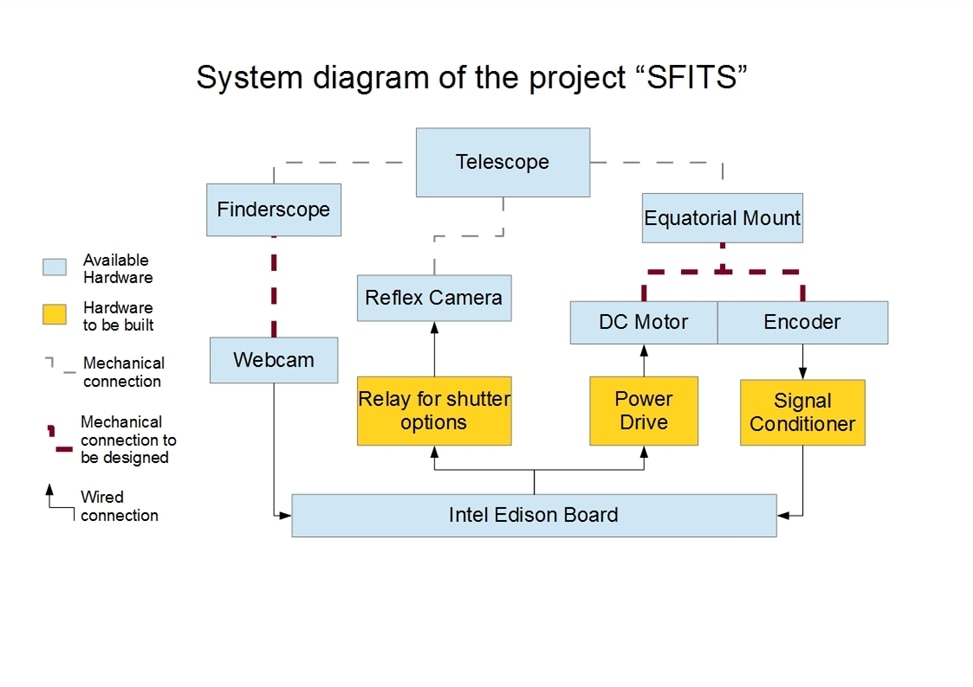
As it can be seen in the legend, three electronic modules have to be developed:
- A module with two relays to control the shutter of the Camera.
- A power module to move the DC motor.
- A signal conditioner module to send the encoder signal to the main board.
As well, two different mechanical parts have to be designed.
- The coupling between the finderscope and the webcam.
- The mounting and coupling of the motor with the encoder to the equatorial mount.
And finally, we reach the software part. A initial software architecture would be as follows.

These are the initial blocks that are necessary. The Software will be developed in Python. The User Interface could be a fancy feature or just the most basic menu. This will be defined later.
I expect the following blocks to be the easiest ones to develop:
- Position and Speed Measurement
- Motor Control
- Shutter Sequence
For the other four blocks, more research and experimentation will be needed.
The Initial plan will be to get the electronic parts for Power Drive and the Signal Conditioner. These two could be used to test the Software Modules of Position and Speed Measurement and Motor Control.
In the next blog entry, I plan to give some results of the investigation about the Power Drive and Signal Conditioner, and a initial design for these boards.
Continue following the project and your comments will be appreciated.
Maker Garcia
Top Comments