


Clem Mayer loves electronic conference badges, so when an event doesn’t have one, there’s only one solution: build his own! Featuring an ESP32-S2, LCD display, six games and SAO expansion, his COMmunity Badge is part name tag, part portable games console and completely hackable, and you can find the supporting files on the element14 Community
Clem Builds His Own Electronic Gaming Badge
Electronic conference badges are one of those little extras that can turn an event into a project in its own right. At their simplest they identify the person wearing them, but the more interesting examples add displays, LEDs, programmable hardware, games and expansion connectors that encourage their owners to keep experimenting long after the event has finished.
Clem Mayer, also known as Mayer Makes, has collected and played with enough of them to know what he likes. There was just one problem: not every event hands out an electronic badge. Rather than accept that, he decided to make his own.
“I do enjoy the badges that you can freely program, so you can put on there whatever you want... But I also would like to have it stand-alone, usable for my enjoyment. So let's put some games on there.”
The resulting Community Badge is a custom PCB that combines a programmable name tag with a small handheld games console. It uses an ESP32-S2, a 128 x 64 pixel LCD, six buttons and an SAO (Simple Add-On) expansion connection, with the whole assembly designed around ordinary AA batteries. It can display a name while being worn at an event, then switch into a selection of games for a train journey, airport wait or any other spare few minutes.
The project is also a useful exercise in designing with components rather than development modules. The LCD is connected directly to the board, the power supply is incorporated into the PCB and the firmware is organised so additional applications can be added without rewriting the badge around them.
Building a Badge Around a Proper LCD
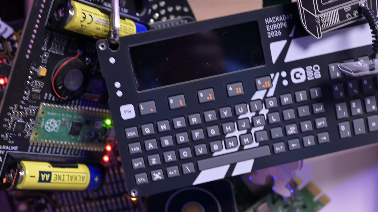
The physical design borrows some familiar cues from classic handheld consoles. There is a large display in the middle, directional controls and action buttons positioned around it, while the PCB itself provides the structure of the badge.
Rather than fitting a ready-made display module, Clem chose a bare Midas chip-on-glass LCD. The display family provides a 128 x 64 pixel graphic panel running with 3.3 V logic and supporting serial/SPI operation. The construction keeps the assembly compact but introduces some considerations that are normally hidden when using an off-the-shelf display breakout.
For example, the LCD connects using a flat-flex cable. Its cable has 28 contacts, but that does not mean a matching 28-position PCB connector is the only option. Clem found that the more readily available 30-position version can accommodate the cable perfectly well, with the unused contacts simply left unused.
“I'm using a 30 pin connector because you can get them easier. And they fit. You don't have to use all the connections on such a connector.”
It is a small design decision, but an important one for anyone recreating a project with a bare display. Connector availability deserves attention before a PCB is committed to manufacture. Clem created the necessary KiCad symbol and footprint himself, including the separate electrical connections needed for the backlight.
The LCD electronics bring another consideration. Although its interface operates at 3.3 V, the panel requires other internal voltages to drive the liquid crystal itself. These are produced by the display's charge-pump circuitry, with external capacitors forming part of that system.
“A lot of issues that you might have with a display boil down to these capacitors and how they are connected to the display. So I keep the traces short, I use high quality caps.”
That is useful practical guidance when laying out the PCB. A display that communicates correctly but behaves unreliably does not necessarily have a software problem. The charge-pump capacitors, their quality and their PCB tracks can all affect correct operation.
Choosing Readability Over Appearance
Clem tried two versions from the same Midas 128 x 64 family. One produces white graphics against a blue background, while the other provides a more conventional black-on-light display. The latter is a transflective FSTN version, whereas the blue version is a transmissive STN display. Both operate with 3.3 V logic, and the family uses chip-on-glass construction.
The blue screen is visually striking, but for a battery-operated badge the more restrained black display turned out to be more useful. It remains easier to read under ordinary ambient lighting without continuously powering its backlight.
“The blue one looks awesome, but it's not as readable as the other one. So in this case, the plain black and not black one, that's the actual better screen for that purpose.”
That readability also helps battery life because the backlight can simply be switched off when it is unnecessary.
There is a considerably more expensive LCD lesson hidden in the build too: do not put this type of chip-on-glass display into an ultrasonic cleaner. Clem tried it after experiencing connection problems and eventually discovered that the process can affect the adhesive holding the layers of the LCD together.
“The ultrasonic cleaner actually dissolves the glue in between the glass and its other layers that it needs to function. And so little bubbles form and suddenly the display just stops randomly working. I did that twice. So don't do that. Save some money.”
A cleaned screen may initially appear unharmed, making the failure particularly unhelpful to diagnose. For anyone assembling their own version of the badge, ordinary electronics cleaning processes therefore need to take the construction of the LCD into account.
Powering a Badge That Has to Travel
A wearable electronic badge needs a power source that suits its intended environment. Clem deliberately avoided a lithium-polymer cell and chose ordinary AA batteries instead. The decision was less about energy density and more about travelling with the finished project.
AA batteries can be replaced quickly and are readily available in shops near most venues. They also avoid the shipping and transport complications that can accompany lithium cells.
“Usually a common battery form factor is easy to replace, easy to source, at the venue or close by. And of course, you can replace them quickly whenever they run out.”
Battery life was important enough for Clem to change another of his usual design habits. He often reaches for a linear regulator when simplicity is the priority, but dissipating the excess voltage in an LDO did not make as much sense here. Instead he implemented a switching regulator.
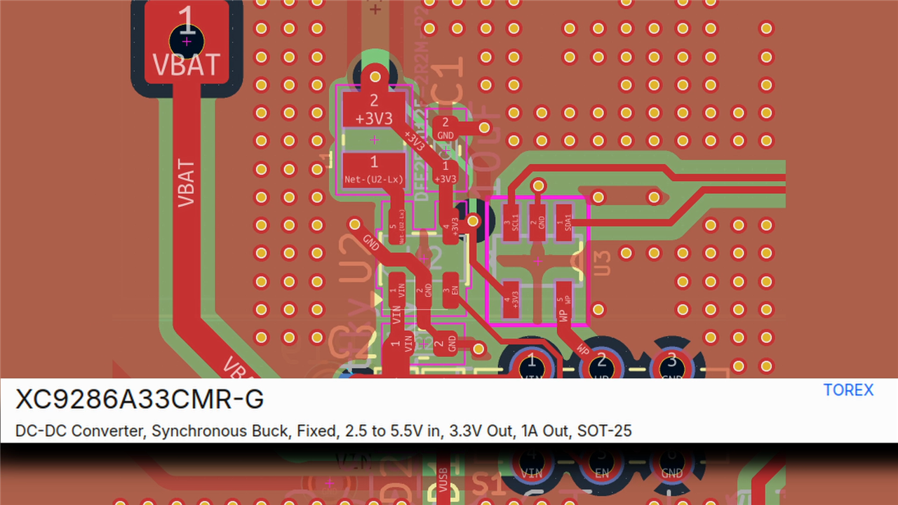
The BOM identifies a Torex XC9286A33CMR-G, a synchronous buck converter producing a fixed 3.3 V output. The device accepts a 2.5 V to 5.5 V input and is rated for up to 1 A of output current, giving the badge useful capacity for its processor, display and connected hardware.
It also demonstrates an approachable way into switch-mode supply design. Rather than attempting to optimise the converter from scratch, Clem selected a device with a straightforward reference design and followed it closely.
“This one just needs an inductor and two caps, so it's barely more complicated than an LDO implementation. But it is about 90 percent efficient... so I use basically the reference design. For now, this seems to work great.”
The supporting parts include a 2.2 µH Murata inductor and 10 µF ceramic capacitors, creating a compact supply around the converter. His experience with it changed his view of switching regulators somewhat: implementing a well-documented reference circuit was manageable, although achieving EMC compliance with a switching supply remains a separate engineering challenge.
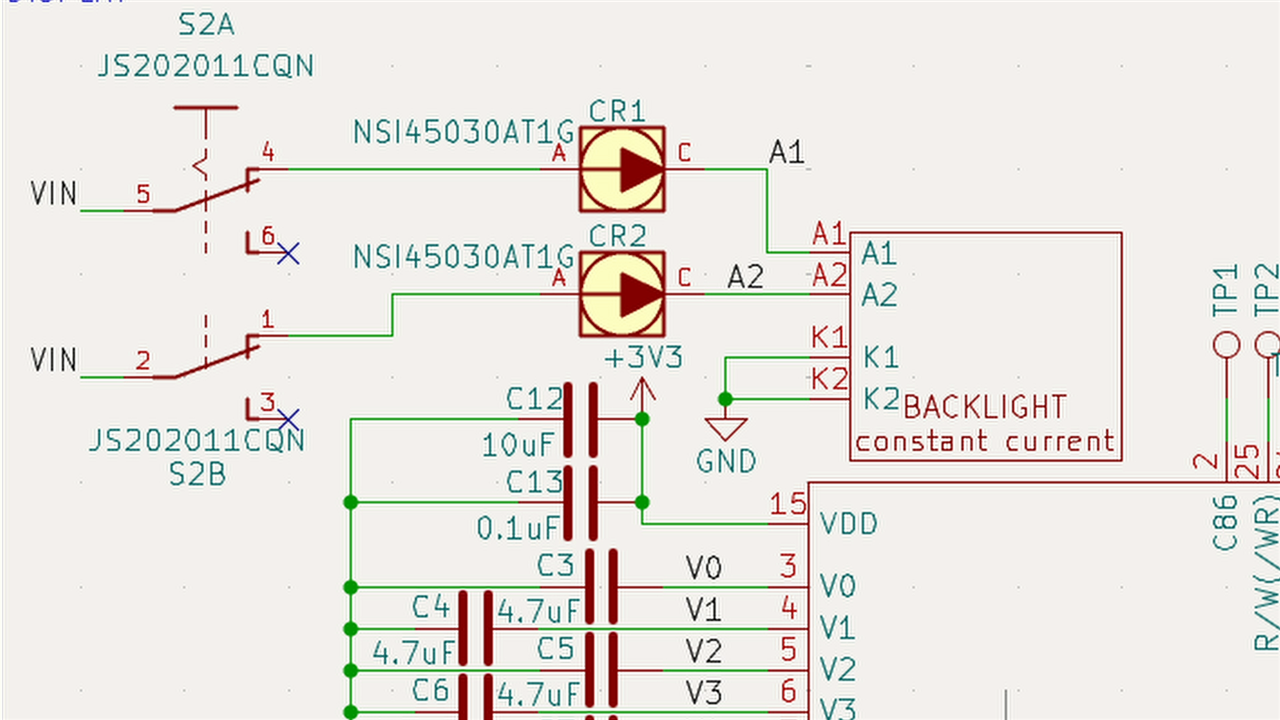
The display backlight receives its own treatment. Rather than merely placing a voltage across its LEDs, each backlight connection uses a two-terminal constant-current regulator. The devices are wired directly into the LED paths and provide a controlled current as the battery voltage changes.
“For my backlight, I have to use constant current driving. Not constant voltage, constant current.”
A physical switch allows the backlight to be disabled when ambient light is sufficient, avoiding an unnecessary continuous load.
The ESP32-S2 and an Application-Based Architecture
The ESP32-S2 sits at the centre of the badge. Native USB was a particularly useful feature for a project intended to be modified at events, because new firmware can be loaded with a USB cable rather than carrying a separate hardware programmer.
“We can program it wherever we are with just a USB cable and we do not need an external specific programmer to do that. Makes it a lot easier for people to put their own code on a badge during an event.”
Rather than making a single monolithic program with all the game logic mixed together, Clem organised the software around separate applications. The main program takes care of common hardware such as the buttons and LCD, presents the application menu and starts the selected item. Individual applications then contain their own behaviour.
That organisation is visible directly in main.cpp, where the badge creates each application and makes them available through a common list:
NameTagApp nametagApp(display);
MillipeterApp millipeterApp(display);
BlockingerApp blockingerApp(display);
BrechausApp brechausApp(display);
PersonalSpaceIntrudersApp personalSpaceIntrudersApp(display);
FrickinBirdApp frickinBirdApp(display);
RoadkillApp roadkillApp(display);

Application *const applications[] = {
  &nametagApp, &millipeterApp, &blockingerApp, &brechausApp,
  &personalSpaceIntrudersApp, &frickinBirdApp, &roadkillApp};
The same file maps the six controls, initialises the display and handles button debouncing. The U8g2 library drives the ST7565-based 128 x 64 LCD with a full frame buffer, giving each application a consistent drawing target.
U8G2_ST7565_ERC12864_F_4W_SW_SPI display(
    U8G2_R0,
    DISPLAY_SCL_PIN,
    DISPLAY_SI_PIN,
    DISPLAY_CS_PIN,
    DISPLAY_DC_PIN,
    U8X8_PIN_NONE);
The result is not an operating system, and it is not intended to be one. It is a small application framework suited to a microcontroller badge.
“The only thing in the main program is a menu that lets you select the apps that you want to run... that way it's easy for you to make your own games or your own applications and just add it to the badge if you want to.”
Each game follows broadly the same arrangement: update the contents of the frame buffer, read the buttons and run the game's own logic. The applications are separated into header and C++ source files, so adding or changing one does not require stuffing more game-specific state into the central program.
AI assistance was used to help implement much of the software under a tight deadline, but Clem approached it by defining the architecture and the responsibilities of individual functions first rather than simply requesting one large program.
“I describe the architecture of my code in detail and each function separately, so it won't mess up as easily.”
That approach is especially relevant on an embedded project where generated software still has to match real GPIO assignments, display behaviour, timing and memory constraints.
A Nametag and Six Games for the Journey Home
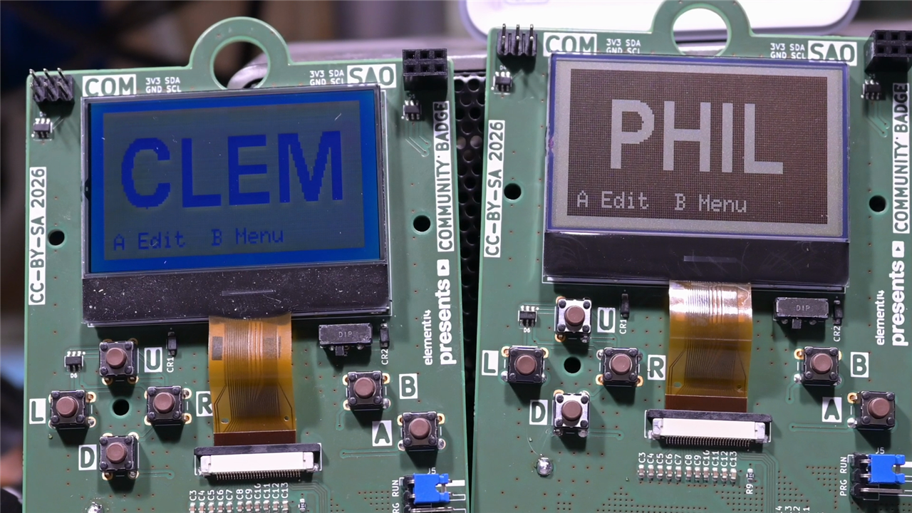
The first application is the reason for wearing the PCB in the first place: the electronic nametag. A name can be edited on the badge and saved, turning the LCD into its day job before the games come out.
There are currently six games alongside it:
- Millipeter, in which an increasingly long creature collects items while avoiding itself and the edges of the screen.
- Blockinger, a falling-block game in which the APP control rotates the pieces.
- Brechaus, a particularly challenging ball-and-paddle brick-breaking game.
- Personal Space Intruders, featuring descending rows of unwelcome visitors.
- Frickin Bird, in which careful button presses keep a flying character clear of obstacles.
- Roadkill, a road-crossing game whose traffic becomes increasingly difficult to avoid.
Millipeter also stores its high score on the badge, giving the otherwise simple game a useful demonstration of persistent state between sessions.
Several of the games exposed opportunities for more work rather than being treated as completely finished pieces of software. Roadkill, for example, ramps the traffic speed as the player succeeds, and Clem found the resulting difficulty curve rather aggressive.
“We might need to adjust the difficulty a bit on here. I think the cars move a bit too fast and guess what? They get faster each round.”
This is one advantage of building the badge around native USB and modular applications. Gameplay adjustments or entirely new applications can be added without changing the hardware.
Adding Hardware Through the SAO Connector
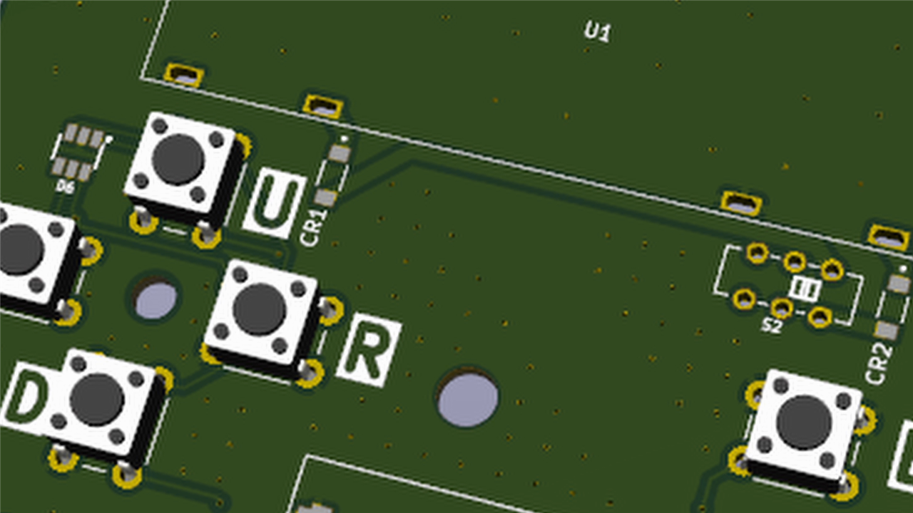
The Community Badge is not restricted to what Clem fitted to its main PCB. An SAO connector allows small external boards to be plugged into the badge, extending it with hardware built by other makers.
SAOs have become part of electronic conference badge culture, with makers designing small boards ranging from blinking decorative pieces to more involved interactive peripherals. There has previously been discussion on the element14 Community about designing an element14 Community badge and SAO, making the expansion connector particularly appropriate for this project.
Clem allowed enough capacity in the 3.3 V supply to accommodate add-on hardware rather than dimensioning the regulator only for the components already fitted to the badge. His target of around one amp gives useful overhead for the microcontroller, display and a modest peripheral attached to the expansion connector.
That does not mean every conceivable add-on can simply be attached without considering its load, but it avoids designing the badge so close to its ordinary current requirement that there is no practical room for experimentation.
A Badge Designed to Be Modified
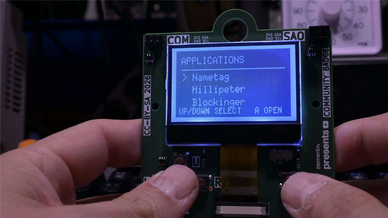
The finished Community Badge succeeds at its original two jobs. Around Clem's neck it is an electronic name tag; with a few button presses it becomes a miniature games machine. More importantly for a maker badge, very little about it is closed off from further experimentation.
Native USB makes reflashing straightforward. The application structure provides somewhere sensible to put a new game. The SAO connector provides a route for additional electronics, and using replaceable AA batteries means the badge can remain useful during a long event without needing a dedicated charger nearby.
The build also produced several practical lessons that are easy to carry into unrelated electronics projects. Bare LCDs need more thought than ready-made modules, particularly around connectors, charge-pump capacitors and backlight current. Availability can make a connector with a couple of unused contacts the better engineering choice. A switching regulator becomes far less intimidating when the manufacturer provides a detailed, appropriate reference circuit. And an ultrasonic cleaner is decidedly not a universal solution for every electronic assembly.
For anyone building their own version, checking the actual display controller against the intended graphics library is another important step. Similar-looking LCD modules can hide different controller ICs, and not every variation is necessarily supported by the same software.
“Always check which display IC is actually built in there, to make sure that the library you want to use is actually compatible... Always check the data sheet of the manufacturer and not just what it says on the product page.”
That combination of practical hardware decisions and deliberately extendable software makes the project much more than a novelty nametag. It is a small, portable development platform disguised as an event badge, with just enough gaming hardware to make the journey home considerably less boring.
And because another application can be dropped into the existing framework, the six games do not have to remain six. The badge was built to be modified, which is precisely the point of taking a programmable badge to a gathering of makers in the first place.
Supporting Files and Links
- Episode 739 Resources - No Conference Badge? Clem Builds the Conference Badge He Always Wanted
Bill of Materials and Parts Used
| Product Name | Manufacturer | Quantity | Buy Kit |
|---|---|---|---|
| MCCOG128064B12W-BNMLW | Midas | 1 | Buy Now |
| MCCOG128064B12W-FPTLW | Midas | 1 | Buy Now |
| F32R-1A7H1-11030 | amphenol | 1 | Buy Now |
| NSI45030AT1G | onsemi | 1 | Buy Now |
| MP000326 | multicomp pro | 1 | Buy Now |
| MC32829 | multicomp pro | 6 | Buy Now |
| XC9286A33CMR-G | torex | 1 | Buy Now |
| DFE252012F-2R2M=P2 | murata | 1 | Buy Now |
| GRM188C81A106KA73D | murata | 2 | Buy Now |
| 2214S-06SG-85 | multicomp pro | 1 | Buy Now |
| 2213S-06G | multicomp pro | 1 | Buy Now |
| MPLSS22-V | multicomp pro | 2 | Buy Now |
Additional Parts
| Product Name | Manufacturer | Quantity |
|---|---|---|
| esp32-s2mini-u1 | espressif | 1 |
