element14 Community
element14 Community
    Register Log In
  • Site
  • Search
  • Log In Register
  • About Us
  • Community Hub
    Community Hub
    • What's New on element14
    • Feedback and Support
    • Benefits of Membership
    • Personal Blogs
    • Members Area
    • Achievement Levels
  • Learn
    Learn
    • Ask an Expert
    • eBooks
    • element14 presents
    • Learning Center
    • Tech Spotlight
    • STEM Academy
    • Webinars, Training and Events
    • Learning Groups
  • Technologies
    Technologies
    • 3D Printing
    • FPGA
    • Industrial Automation
    • Internet of Things
    • Power & Energy
    • Sensors
    • Technology Groups
  • Challenges & Projects
    Challenges & Projects
    • Design Challenges
    • element14 presents Projects
    • Project14
    • Arduino Projects
    • Raspberry Pi Projects
    • Project Groups
  • Products
    Products
    • Arduino
    • Avnet Boards Community
    • Dev Tools
    • Manufacturers
    • Multicomp Pro
    • Product Groups
    • Raspberry Pi
    • RoadTests & Reviews
  • Store
    Store
    • Visit Your Store
    • Choose another store...
      • Europe
      •  Austria (German)
      •  Belgium (Dutch, French)
      •  Bulgaria (Bulgarian)
      •  Czech Republic (Czech)
      •  Denmark (Danish)
      •  Estonia (Estonian)
      •  Finland (Finnish)
      •  France (French)
      •  Germany (German)
      •  Hungary (Hungarian)
      •  Ireland
      •  Israel
      •  Italy (Italian)
      •  Latvia (Latvian)
      •  
      •  Lithuania (Lithuanian)
      •  Netherlands (Dutch)
      •  Norway (Norwegian)
      •  Poland (Polish)
      •  Portugal (Portuguese)
      •  Romania (Romanian)
      •  Russia (Russian)
      •  Slovakia (Slovak)
      •  Slovenia (Slovenian)
      •  Spain (Spanish)
      •  Sweden (Swedish)
      •  Switzerland(German, French)
      •  Turkey (Turkish)
      •  United Kingdom
      • Asia Pacific
      •  Australia
      •  China
      •  Hong Kong
      •  India
      •  Korea (Korean)
      •  Malaysia
      •  New Zealand
      •  Philippines
      •  Singapore
      •  Taiwan
      •  Thailand (Thai)
      • Americas
      •  Brazil (Portuguese)
      •  Canada
      •  Mexico (Spanish)
      •  United States
      Can't find the country/region you're looking for? Visit our export site or find a local distributor.
  • Translate
  • Profile
  • Settings
Ben Heck Featured Content
  • Challenges & Projects
  • element14 presents
  • element14's The Ben Heck Show
  • Ben Heck Featured Content
  • More
  • Cancel
Ben Heck Featured Content
Forum Engine Management
  • Blog
  • Forum
  • Documents
  • Events
  • Polls
  • Files
  • Members
  • Mentions
  • Sub-Groups
  • Tags
  • More
  • Cancel
  • New
Join Ben Heck Featured Content to participate - click to join for free!
Actions
  • Share
  • More
  • Cancel
Forum Thread Details
  • Replies 63 replies
  • Subscribers 46 subscribers
  • Views 4132 views
  • Users 0 members are here
Related

Engine Management

jack.chaney56
jack.chaney56 over 9 years ago

Hi Ben,

I am a programmer with a very small amount of skill with circuits, and am looking to create a platform for an engine management system, using an Arduino Mega 2560. I had done a bit of the coding, when I ran into some timing issues with the built in Arduino manager, so I switched over and started using AVR Studio and a programmer to go directly to the chip itself.  The code looks like it should work ok, but now I need some additional circuits to handle the energy levels of coils and injectors (Something like IGBTs). Sensors are being run through simple dividers (no protection yet), and cam and crank inputs are through a simple comparitor


Let me know what you think,

Jack

  • Sign in to reply
  • Cancel

Top Replies

  • jack.chaney56
    jack.chaney56 over 7 years ago +2
    Back again... After a bit of time away seeking enlightenment (and a steady paycheck), I am ready to get back to work on my project. I have continued to play around with the code and a number of components…
  • jack.chaney56
    jack.chaney56 over 7 years ago +2
    I want to start this thing right, so the shopping list for people that want to play along at home: Raspberry Pi - version is not significant if you don't mind a slow response when using Eclipse, but 3B…
  • jack.chaney56
    jack.chaney56 over 7 years ago +2
    Start off with two things. First, I forgot (neglected) to provide instruction on how to get the compiled code onto the Nano. Fault of familiarity; having done the process so many times, I had shifted to…
  • rsc
    rsc over 7 years ago in reply to jack.chaney56

    I'm trying to think of who Fred is...…...I worked for Kissel, then Cwiek.

    I remember watching them build the first Dodge Viper in the plastics shop on a dune buggy frame in HP.

    Scott

    • Cancel
    • Vote Up 0 Vote Down
    • Sign in to reply
    • Cancel
  • jack.chaney56
    jack.chaney56 over 7 years ago

    I want to start this thing right, so the shopping list for people that want to play along at home:


    Raspberry Pi - version is not significant if you don't mind a slow response when using Eclipse, but 3B+ if this is a new set up

    - all the stuff to make a RPi a working desktop (SD card, keyboard, mouse, monitor, power supply, and cabling)

    - internet connection is also handy, but not mandatory for the workstation after configuration.

    Breadboard(s) - the usual kind so outboard components can get attached.

    image

    Arduino Nano - this will be the controller platform for the project

    Arduino Nano

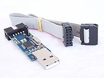
    Programmer - Pretty much any programmer for AVR that has the 6pin connector

    imageimage

    That is pretty much it for the moment, Probably want to get two of the Atmel units. I have a plan to use one as a signal generator for cam and crank signals.


    I'll leave the description of initial set up of the Raspberry Pi to the experts, just go through the basic steps to get a version of Raspbian up and running.

    Then do the obligatory sudo apt-get update; sudo apt-get -y upgrade step.

    Install the AVR components (using the installer type AVR in the search box)

    - gcc-avr

    - gdb-avr

    - avr-libc

    - binutils-avr

    - avrdude

    - debug symbols for avrdude

    Next install Eclipse IDE (using the installer type eclipse in the search box)

    - Extensible Tool Platform (eclipse)

    - C/C++ Development tools for Eclipse (eclipse-cdt)


    Last add the AVR plugin to Eclipse. First start Eclipse and agree to the workspace popup. Next go to:

         Help->Install New Software

    In the work box, enter: http://avr-eclipse.sourceforge.net/updatesite/ and say Add, and when asked name it AVR and say OK

    Next window click the checkbox for the offering and select Next

    Keep agreeing with all the boxes, accept the license agreement and finish.

    You will need to restart Eclipse when asked.


    It might be a good idea to be sure you have a good text editor (this I will leave to you, as text editors are very personal attachments).

    It is also a good idea to install a configuration management system like GIT or Mecurial and add the Eclipse plugin (GIT is already on Raspbian).


    Once things are up and running, it is always nice to test things out with a "Hello, world!" example.

    First start Eclipse, and after it starts, from the menu bar select File->New->Project Then select the type of project, C++ Project and say Next (not Finish)

    This is for an AVR project, so in the next window select AVR Cross Target Application->Empty Project name the project appropriately, then say Next (again, not Finish)

    Say Next for the debug selections.

    Last, select the processor and speed, the processor can be selected from the dropdown, for the Nano, it is an ATMega328p, and the MCU Frequency is 16000000Hz.


    Since this is the first project, it will say "Due to selection, it is appropriate to use the C/C++ interface" and "is this OK?"; just agree.


    In the icon bar at the top (middle) there is a box with a C on it. This runs the wizard to make a C/C++ file, just remember to include the .c extension.

    In the open file, type the usual...

    #include <stdio.h>


    int main(void) {


         printf("Hello, world!\n");

         return 0;

    }


    Save the file and build using the little hammer icon in the icon bar.


    ...hopefully you can now say "Ta Da!"


    More to come,

    Jack

    • Cancel
    • Vote Up +2 Vote Down
    • Sign in to reply
    • Cancel
  • jack.chaney56
    jack.chaney56 over 7 years ago

    Next part to keep your interest...

    Three files and a modify of the main from before.

    First one, because coding standards don't tend to be standard, I like to have a types.h file so I can work without having to think too much.


    /***************************************************************************************************
     All code provided is original and developed by Jack Chaney. Any similarity to code existing in
     another location or form is purely coincidental. The code presented caries with it no guarantee
     outside my statements that IT WORKED FOR ME.
     
     If, in the future this code is used in any products, please provide proper recognition for my
     efforts.
     
     Jack Chaney, 2018 Chaney Firmware
     
     This is the base include file, that pulls in all the AVR components, and standard items to make
     life easier. I also declare some items for variable naming that makes it easier for me
     to run on auto pilot.
    ***************************************************************************************************/
    #ifndef _TYPES_H
    #define _TYPES_H
    #include <stdbool.h>
    #include <stdio.h>
    #include <avr/interrupt.h>
    #include <avr/io.h>
    
    typedef unsigned char  UByte;
    typedef char           SByte;
    typedef unsigned short UWord;
    typedef short          SWord;
    typedef unsigned long  ULong;
    typedef long           SLong;
    
    /* Hardware interfacers */
    #define REG_B(a)      *((volatile UByte* const)(a))
    #define REG_W(a)      *((volatile UWord* const)(a))
    #define REG_L(a)      *((volatile ULong* const)(a))
    #define REG_Bs(a)     *((volatile SByte* const)(a))
    #define REG_Ws(a)     *((volatile SWord* const)(a))
    #define REG_Ls(a)     *((volatile SLong* const)(a))
    #define ARR_B(a)      ((UByte* const)(a))
    #define ARR_W(a)      ((UWord* const)(a))
    #define ARR_L(a)      ((ULong* const)(a))
    #define ARR_Bs(a)     ((SByte* const)(a))
    #define ARR_Ws(a)     ((SWord* const)(a))
    #define ARR_Ls(a)     ((SLong* const)(a))
    
    /* some use while(1) but I found this way compiles to fewer instructions */
    #ifdef forever
    #undef forever
    #endif
    #define forever    for(;;)
    
    /* handy bits */
    #define bit0    1
    #define bit1    2
    #define bit2    4
    #define bit3    8
    #define bit4    16
    #define bit5    32
    #define bit6    64
    #define bit7    128
    #define bit8    256
    #define bit9    512
    #define bit10    1024
    #define bit11    2048
    #define bit12    4096
    #define bit13    8192
    #define bit14    16384
    #define bit15    32768
    
    #endif
    /* end of file */


    The second file is a simple configuration for the timers, to provide two components; a mS time base, and a running clock.

    /***************************************************************************************************
     All code provided is original and developed by Jack Chaney. Any similarity to code existing in
     another location or form is purely coincidental. The code presented caries with it no guarantee
     outside my statements that IT WORKED FOR ME.
     
     If, in the future this code is used in any products, please provide proper recognition for my
     efforts.
     
     Jack Chaney, 2018 Chaney Firmware
    ***************************************************************************************************/
    #include "types.h"
    
    #define TIMSK0_INIT  (1<<OCIE0A)
    #define TIMSK2_INIT  0
    #define TIMSK1_INIT  (1<<TOIE1)
    #define TCCR0A_INIT  0
    #define TCCR0B_INIT  (3<<CS00)
    #define TCCR2A_INIT  0
    #define TCCR2B_INIT  (3<<CS00)
    #define TCCR1A_INIT  0
    #define TCCR1B_INIT  (2<<CS10)
    #define TCCR1C_INIT  0
    
    #define mS_UPDATE_8  250
    
    SLong ov0Tic;
    SLong ov2Tic;
    SLong ov1Tic;
    SLong getTime1(void) { ULong rVal; cli(); rVal = (ov1Tic | TCNT1); sei(); return rVal; }
    
    void initTimers(void) {
     TCCR0A = TCCR0A_INIT; TCCR0B = TCCR0B_INIT; TIMSK0 = TIMSK0_INIT;
     TCCR2A = TCCR2A_INIT; TCCR2B = TCCR2B_INIT; TIMSK2 = TIMSK2_INIT;
     TCCR1A = TCCR1A_INIT; TCCR1B = TCCR1B_INIT; TCCR1C = TCCR1C_INIT; TIMSK1 = TIMSK1_INIT;
    }
    
    ISR(TIMER0_COMPA_vect) {
     OCR0A += mS_UPDATE_8;  /* refresh for 1mS Timer Tic */
    }
    
    ISR(TIMER0_OVF_vect) { ov0Tic = (ov0Tic +   256L) & 0x07ffff00; }
    ISR(TIMER2_OVF_vect) { ov2Tic = (ov2Tic +   256L) & 0x07ffff00; }
    ISR(TIMER1_OVF_vect) { ov1Tic = (ov1Tic + 65536L) & 0x3fff0000; }
    /* end of file */


    The third uses the 328 interrupt inputs, which will be the cam and crank input signals.

    /***************************************************************************************************
     All code provided is original and developed by Jack Chaney. Any similarity to code existing in
     another location or form is purely coincidental. The code presented caries with it no guarantee
     outside my statements that IT WORKED FOR ME.
     
     If, in the future this code is used in any products, please provide proper recognition for my
     efforts.
     
     Jack Chaney, 2018 Chaney Firmware
    ***************************************************************************************************/
    #include "types.h"
    
    #define EICRA_INIT   (1<<ISC00)|(1<<ISC10) /* Trigger INT0 and INT1 on either edge */
    #define EIMSK_INIT   (1<<INT0)|(1<<INT1)  /* Set INT0 and INT1 active */
    
    bool isCrkRising(void) { return false; } /* these are future calibration values, but for now force the false falling edge */
    bool isCamRising(void) { return false; }
    bool isInt0Low(void) { return ((PIND & (1<<PD2)) != 0); }
    bool isInt1Low(void) { return ((PIND & (1<<PD3)) != 0); }
    
    SLong crkTime;
    SLong crkDiff;
    SLong camTIme;
    SLong camDiff;
    
    UByte toothAfterCam;
    
    void initIgn(void) {
     EICRA = EICRA_INIT;
     EIMSK = EIMSK_INIT;
     crkTime = camTime = 0;
     toothAfterCam = 0;
    }
    void rtUpdateIgn(void) { /* not used yet, but a place holder */
    }
    /**************************************************************************************************
     Crank interrupt
     Interrupt is called on both rising and falling edges of crank signal.
     - Active edge is defined as falling edge, or rising edge
        Active edge is determined as falling and signal low, or rising and signal high.
     - Primary activity for the interrupt is to determine angular velocity and cam angle
       Using high speed clock timer, obtain current time as tempTime
       and using previous time (crkTime) calculate a difference between active signals.
     - Preserve time and difference as crkTime and crkDiff
    **************************************************************************************************/
    ISR(INT0_vect) {
     SLong tmpTime = getTime1();
     SLong tmpDiff = tmpTime + (tmpTime > crkTime ? 0 : 0x40000000) - crkTime;
    /**************************************************************************************************
     Because the timer has a limit of a max value before rollover, the 32 bit number is limited
     to only using 30 bits before rollover. At rollover occurrence a factor is added to retain
     the proper value for DIFF. TIME is unaffected.
    **************************************************************************************************/
     if (isInt0Low() ^ isCrkRising()) {
    /**************************************************************************************************
      use the cam signal to locate the tooth
    **************************************************************************************************/
      toothAfterCam++;
      if (isCamDet()) {
       setCamDet(false); /* cam detected so clear the flag */
       toothAfterCam = 0;
      }
      crkTime = tmpTime;
      crkDiff = tmpDiff;
     }
    }
    /**************************************************************************************************
     Cam interrupt
    **************************************************************************************************/
    ISR(INT1_vect) {
     SLong tmpTime = getTime1();
     SLong tmpDiff = tmpTime + (tmpTime > crkTime ? 0 : 0x40000000) - camTime;
     if (isInt1Low() ^ isCamRising()) {
      setCamDet(true); /* simple signal for now */
      camTime = tmpTime;
      camDiff = tmpDiff;
     }
    }
    /* end of file */


    To update the main from before just have it make calls to:

    initTimers(); and initIgn();


    there aren't any outputs yet so if you compile and load it on the Nano, you won't get anything visible happening.  The code is presented as a starting point. Read the comments and ask questions.  Each of the sections are going to be expanded.  The cam will add conditional mechanisms for MOPAR, and VVT decoding, and crank will have a missing or filled tooth detection part as well.


    If this looks familiar, it's because this part hasn't changed much from my stuff before.


    Enjoy,

    Jack

    • Cancel
    • Vote Up +1 Vote Down
    • Sign in to reply
    • Cancel
  • jack.chaney56
    jack.chaney56 over 7 years ago

    Start off with two things.  First, I forgot (neglected) to provide instruction on how to get the compiled code onto the Nano. Fault of familiarity; having done the process so many times, I had shifted to auto-pilot. If anyone had not done this before, it is probably a good idea to go over how to accomplish it.


    From Eclipse, on the icon bar, there is a button that says AVR with an arrow. This is the "Upload current project to Atmel target MCU" button. Until you configure it, it will complain. First, highlight the project in the window to the left then on the menu bar select Project->Properties then AVR->AVRDude in the Programmer tab, Programmer configuration, click on Edit and select the programmer you are using from the list. The super cheep kind is probably USBasp down toward the bottom of the list. Remember to enter the Configuration name before you say OK, and ok your way back out.


    The AVRDude program looks for an AVR Release so go to Project->Build Configurations->Set Active and choose 2 Release. Then rebuild your project. All set...


    Plug the USB for the programmer into the workstation USB port, Plug the 6way programmer onto the Nano programmer pins, and plug the Nano USB into a power source, or the USB of the workstation. Then click on the AVR button on the icon bar and the process starts.  It takes a moment but will return with a status of the operation.


    Second, It is always good to have a communication channel to the outside world. The Nano conveniently has a USB serial port built in, and the programming of the Tx/Rx lines is actually quite simple (especially since I have done it on dozens of other systems). The workstation will need software also. I use PuTTY, because it is easy to get, easy to install, portable to other systems, and is free. PuTTY defaults to SSH, so it needs to be configured as a Serial, so click on the Serial radio button. Set the Serial line to the communication port that talks to the Nano (example: /dev/ttyUSB0). This can be found when you plug the Nano into the USB port, then read the device information (on Linux, just run dmesg and it will probably be at the bottom of the list). Then set the Speed to the baud rate in use (the source I am presenting is 19200). Last, Enter a name in the Saved Sessions box and click Save to preserve the settings. When you come back, just click on the entry in the Saved Sessions table.


    Now the source... This is a straight forward serial communication implementation. It uses input and output buffering, and runs both input and output as interrupt processes. The advantage is the program can dump the full string into the output buffer, and go back to work, not having to wait for each character to be sent. Similarly, it is not critical for the program to respond to each character and can fetch instructions as a whole when they are sent.

    /***************************************************************************************************
     All code provided is original and developed by Jack Chaney. Any similarity to code existing in
     another location or form is purely coincidental. The code presented caries with it no guarantee
     outside my statements that IT WORKED FOR ME.
     
     If, in the future this code is used in any products, please provide proper recognition for my
     efforts.
     
     Jack Chaney, 2018 Chaney Firmware
    ***************************************************************************************************/
    #include "types.h"
    #define UBAUD_57_6    34
    #define UBAUD_38_4    51
    #define UBAUD_19_2    103
    #define UBAUD__9_6    207
    
    #define BUFFSIZE      32
    
    #define TXI0          (1<<TXCIE0)
    #define UCSRA_INIT    (1<<U2X0)                           /* Timebase for UART 2x clock */
    #define UCSRB_INIT    (1<<TXEN0)|(1<<RXEN0)|(1<<RXCIE0)   /* Enable transmit and receive lines and receive interrupt */
    #define UCSRC_INIT    (3<<UCSZ00)|(0<<UPM00)|(0<<UMSEL00) /* n-8-1 */
    #define COMMSPEED     UBAUD_19_2                          /* 19200 */
    
    static UByte rxBuf[BUFFSIZE];
    static UByte txBuf[BUFFSIZE];
    static volatile UByte rxHed, rxTal, rxSiz;
    static volatile UByte txHed, txTal, txSiz;
    
    bool isComReady(void) { return (rxSiz != 0); }
    
    void initUart(void) {
     UCSR0A = UCSRA_INIT;
     UCSR0B = UCSRB_INIT;
     UCSR0C = UCSRC_INIT;
     UBRR0 = COMMSPEED;
     rxHed = 0; rxTal = 0; rxSiz = 0;
     txHed = 0; txTal = 0; txSiz = 0;
    }
    /*==============================*/
    /*       *** WARNING ***        */
    /*  Do not use these functions  */
    /*     within an interrupt      */
    /*==============================*/
    void putCom(UByte c) {
     if ((UCSR0B & TXI0) == 0) {                              /* output buffer empty and no byte currently being sent */
      UDR0 = c; UCSR0B |= TXI0;                               /* put byte in output port, and turn on the interrupt */
     } else {
      while (txSiz >= BUFFSIZE);                              /* make sure there is room in the buffer, or wait (see warning) */
      cli();                                                  /* turn off interrupts, for safety */
      txBuf[txTal] = c;                                       /* put the byte on the end of the buffer */
      txTal = (txTal + 1) < BUFFSIZE ? txTal + 1 : 0;         /* adjust the pointer */
      txSiz++;                                                /* increment the character counter */
      sei();                                                  /* all done so turn the interrupts back on */
     }
    }
    UByte getCom(void) {
     UByte c = 0;
     if (rxSiz > 0) {                                         /* if there isn't an input byte, just return 0 */
      cli();                                                  /* turn off interrupts, for safety */
      c = rxBuf[rxHed];                                       /* fetch the byte from the head of the buffer */
      rxHed = (rxHed + 1) < BUFFSIZE ? rxHed + 1 : 0;         /* adjust the pointer */
      --rxSiz;                                                /* decrement the character counter */
      sei();                                                  /* all done so turn the interrupts back on */
     }
     return c;
    }
    /*==============================*/
    ISR(USART_RX_vect) {                                      /* interestingly, the interrupt looks just like the runtime */
     UByte c = UDR0;                                          /* fetch the byte from the input port */
     if (rxSiz < BUFFSIZE) {                                  /* make sure there is room in the buffer, but because it is the interrupt, can't wait */
      cli();                                                  /* block the other interrupts, for safety */
      rxBuf[rxTal] = c;                                       /* put the byte on the end of the buffer */
      rxTal = (rxTal + 1) < BUFFSIZE ? rxTal + 1 : 0;         /* adjust the pointer */
      rxSiz++;                                                /* increment the character counter */
      sei();                                                  /* all done so turn the interrupts back on */
     } else { /* Dropped bytes go here */ }
    }
    ISR(USART_TX_vect) {                                      /* this could nearly be a cut and paste, but the buffer names are swapped */
     UByte c;
     if (txSiz > 0) {                                         /* special case for last one out */
      cli();                                                  /* block the other interrupts, for safety */
      c = txBuf[txHed];                                       /* fetch the byte from the head of the buffer */
      txHed = (txHed + 1) < BUFFSIZE ? txHed + 1 : 0;         /* adjust the pointer */
      --txSiz; UDR0 = c;                                      /* decrement the character counter, and put the byte in the output port */
      sei();                                                  /* all done so turn the interrupts back on */
     } else {
      UCSR0B &= ~TXI0;                                        /* last byte out
     }
    }
    /* end of file */

    Same as before, add initUart() to the start up. The main() process can loop to listen for isComReady(), then getCom() and putCom(c); just like you would think.

    • Cancel
    • Vote Up +2 Vote Down
    • Sign in to reply
    • Cancel
  • jack.chaney56
    jack.chaney56 over 7 years ago in reply to jack.chaney56

    I hate when I have a lapse in content. I was looking through the previous information and noticed a glaring problem... the code for the timers, is practically devoid of comments. I think it is because I was doing a bunch of cut and paste to provide the material in an incremental fashion (not making people drink from a fire hose). I will be sure to be mindful of not letting that happen again, and in the meantime...


    First the grouping of 0 and 2 are because the 328 has one 16 bit and two 8 bit timer counters. In some form of infinite wisdom, they made timer 0 an 8 bit, then timer 1 a 16 bit, but went back to an 8 bit for timer 2.  As a result, I made one of the 8 bit timers my 1mS real-time, timekeeper, so I could preserve the 16 bit counter to have special duties. To make the 8 bit work for a 1mS period, I slowed the clock so 250 tics would make for a 1mS elapsed time. Because the 16 bit clock has a wider counter space, I bumped the speed so it is able to have 2000 tics per mS.  This explains the settings for the TCCR registers. For now, I have two interrupts running, one is the timer 0 compare A, which is used for the 1mS timer. The second is the timer 1 overflow. The other timer interrupts will be called into service in a future installment


    There are also overflow interrupts, that enable a counter extension, providing the upper 16 bits of a 32 bit counter. For the 16 bit counter, the overflow adds 65536 or 216, and for the 8 bit counter, the overflow adds 256 or 28.


    Lastly, because of the speed difference, the slower 8 bit timer actually very closely synchronizes with the 16 bit by shifting the 16 bit right 3 bits. The other element is to limit the size of the counter value to 30 bits for the fast timer, and 27 bits for the slow timer.

    • Cancel
    • Vote Up 0 Vote Down
    • Sign in to reply
    • Cancel
  • jack.chaney56
    jack.chaney56 over 7 years ago

    Two more modules that will provide interfaces to the rest of the hardware in the 328, are the A/Ds and the EEPROM.  First the A/D which is an 8 channel 10 bit device. It runs quite fast, but I wanted to have it operate invisibly in the background and not poll the line and wait for the conversions to complete, so it runs as an interrupt operation.

    /***************************************************************************************************
     All code provided is original and developed by Jack Chaney. Any similarity to code existing in
     another location or form is purely coincidental. The code presented caries with it no guarantee
     outside my statements that IT WORKED FOR ME.
     
     If, in the future this code is used in any products, please provide proper recognition for my
     efforts.
     
     Jack Chaney, 2018 Chaney Firmware
    ***************************************************************************************************/
    #include "types.h"
    #define ADCSRA_INIT   (7<<ADPS0)     /* Right aligned Free running /64 prescaler */
    #define A2D_CHAN   8                 /* number of A/D channels */
    #define A2D_FILTER   8               /* 8 to 1 filter */
    #define A2D_HALF   (A2D_FILTER/2)    /* used for rounding the result */
    
    static UByte a2dSemi4;               /* pseudo semaphore, are updates being done */
    static SWord a2dVal[A2D_CHAN];
    static UByte a2dChan;                /* current converting A/D */
    
    SWord getA2d(UByte v) { return (v < A2D_CHAN ? ((a2dVal[v] + A2D_HALF) / A2D_FILTER) : 0); }
    
    void initA2D(void) {
     a2dSemi4 = 0;                       /* pseudo semaphore, to only run the conversions when ready */
     for (a2dChan = 0; a2dChan < A2D_CHAN; a2dChan++) {
      a2dVal[a2dChan] = 0;               /* clear the buffer */
     }
     ADCSRA = ADCSRA_INIT;               /* configure the A/D */
    }
    void rtUpdateA2D(void) {
     if (a2dSemi4 == 0) {                /* don't run if semaphore is active(already running) */
      a2dSemi4 = 1;                      /* started, so set the semaphore on */
      a2dChan = 0;                       /* start with the first A/D */
      ADMUX = a2dChan;                   /* set the A/D channel */
      ADCSRA |= (1 << ADEN);             /* enable the A/D channel */
      ADCSRA |= (1 << ADSC);             /* start the A/D conversion */
      ADCSRA |= (1 << ADIE);             /* turn on the interrupt */
     }
    }
    ISR(ADC_vect) {
     SWord tmp = ADC;                    /* conversion complete, so fetch the A/D value */
     ADCSRA &= ~(1<<ADEN);               /* disable the A/D while changing the MUX */
    /* the filtering is a running average... remove one part and add in the new as replacement */
     a2dVal[a2dChan] += tmp - (a2dVal[a2dChan] / A2D_FILTER);
     a2dChan++;                          /* point to the next channel */
     if (a2dChan < A2D_CHAN) {           /* check to see if all the channels are done */
      ADMUX = a2dChan;                   /* set the A/D channel */
      ADCSRA |= (1 << ADEN);             /* enable the A/D channel */
      ADCSRA |= (1 << ADSC);             /* start the A/D conversion */
     } else {
      ADCSRA &= ~(1 << ADIE);            /* all the channels read, so turn off the interrupt */
      a2dSemi4 = 0;                      /* and clear the interrupt */
     }
    }
    /* end of file */


    The EEPROM code is nearly lifted verbatim from the Atmel documentation, so no real explanation.

    /***************************************************************************************************
     All code provided is original and developed by Jack Chaney. Any similarity to code existing in
     another location or form is purely coincidental. The code presented caries with it no guarantee
     outside my statements that IT WORKED FOR ME.
     
     If, in the future this code is used in any products, please provide proper recognition for my
     efforts.
     
     Jack Chaney, 2018 Chaney Firmware
    ***************************************************************************************************/
    #include "types.h"
    
    UByte getEEPROM(UWord ofs) {
     UByte rVal = 255;
     if (ofs <= E2END) {
      while(EECR & (1 << EEPE)); EEAR = ofs;
      EECR |= (1 << EERE); rVal = EEDR;
     }
     return rVal;
    }
    void putEEPROM(UWord ofs, UByte d) {
     if (ofs <= E2END) {
      while(EECR & (1 << EEPE)); EEAR = ofs;
      EEDR = d; EECR |= (1 << EEMPE); EECR |= (1 << EEPE);
     }
    }
    /* end of file */

    • Cancel
    • Vote Up +2 Vote Down
    • Sign in to reply
    • Cancel
  • jack.chaney56
    jack.chaney56 over 7 years ago in reply to rsc

    Hi Scott,

    Came over from AMC/Jeep (Plymouth Rd). Fred was Meisterfeld. and Dale Koch. Was part of Neon Launch (dare to be different). Then went over to IT to work on DRBIII.


    Jack

    • Cancel
    • Vote Up 0 Vote Down
    • Sign in to reply
    • Cancel
  • mp2100
    mp2100 over 7 years ago in reply to jack.chaney56

    I will admit I haven't (yet) read through in detail your posts, but, I do like your disclaimer in your code.  If I can remember next time I start a new project, I would like to copy that.  Or a reasonable facsimile.  If you don't object.


    1. All code provided is original and developed by Jack Chaney. Any similarity to code existing in
    2. another location or form is purely coincidental. The code presented caries with it no guarantee
    3. outside my statements that IT WORKED FOR ME.
    • Cancel
    • Vote Up 0 Vote Down
    • Sign in to reply
    • Cancel
  • jack.chaney56
    jack.chaney56 over 7 years ago in reply to mp2100

    Hi Allen,

    Sure... I figure as soon as I post stuff here, it is going to be scooped up and used by more than a few people. The important part is actually the next that asks to remember me when you become rich and famous.  I didn't put it in the header, but I usually add a history line.


    History: Original Creation, as the earth was cooling.


    Which is to say, most of this stuff is derived from methods I have been using for a really long time.


    Might as well say it here, the code to this point, will make the Nano into a fully usable device with no non custom code. The Arduino interface is really nice for people learning how to use it, but really slows things down if you are trying to make things run as fast as possible.


    Jack

    • Cancel
    • Vote Up 0 Vote Down
    • Sign in to reply
    • Cancel
  • jack.chaney56
    jack.chaney56 over 7 years ago

    Back again...

    The next installment is to discuss units of measure and how to look at things from the computer's point of view.  The first measurement and the one that will be used first in the example is measurement of angle. If you have taken lots of math classes and had Geometry, you would probably remember a lot of this stuff, but if you haven't had the classes, and only kind of understand how angles work, I will provide an explanation in a method that I hope will be easy to understand. The angle system is based on the points of a circle, and a line drawn from the perimeter of the circle to the center. If you draw two lines from the perimeter to the center, the two lines come together at an angle. Map makers established a measurement system for angles and declared the unit of measure to be degrees, and there were 360 degrees in a circle. Which is to say the measurement of degrees around the circle increases, until the points join. This is a measurement of 360 degrees.


    Math moves forward, and a need for measuring the distance around the circle was needed, so a ratio between the distance from the perimeter to the center is called the radius, and the distance around the perimeter is called the circumference. Long ago it was proven that no matter what the radius of the circle was, the ratio between radius and circumference was a constant and circumference. That constant is named pi where circumference = 2 * pi * radius. Lots of work to determine the exact value of pi has been attempted over the years, and memorization of digits of pi has been a point of contest for nearly as long. Which led to another unit of angular measure called radians where 360 degrees equated to 2pi.


    With that background, I can now bring in my update. A circle having 2pi radians, and pi being a constant number, and because a significant amount of derivation of geometric formulas have been performed, if pi is thought of as just a constant, it is possible to use a binary constant, and if a conversion is provided, all the math will remain. My goal was to use a numbering system that worked well for computers, which operate in binary, and to avoid using floating point to maintain processing speed. I settled on using a 16 bit integer as a base value with a sign, and a signed integer limits to +/- 215. The result then would make the value of 2pi = 32678, so pi would equate to 16384, and when necessary, a constant conversion is possible to invoke. In the meantime, much of the world, and most of the people working with engine management, work with degrees, and if 360 degrees equates to 32768, the measurement of angle is +/- 0.0109 degrees, which is a decent tolerance. There is a secondary advantage for using this method, which is, in a four cycle system, because the cam cycle is two rotations, and it is necessary to know the position in the cam cycle, by using an unsigned 16 bit value, the calculations become greatly simplified.


    With all that explained, I will add one more element to the process. Because in fixed point (integer) operation, you don't want your number to become too big or too small, I am introducing a PART1 and PART2 values. These numbers when multiplied equate to the total degrees in the circle (DEG_PER_REV) which from previous is 32768. PART1 and PART2 are also selected as binary constants, so multiplication or division is performed as a simple left or right bit shift, and in source code, the simple addition of:


    #define PART1    64L        /* part 1 of full circle for calculations */
    #define PART2    512L       /* part 2 of full circle for calculations */
    #define DEGS_PER_REV  (PART1*PART2)


    Since this is used in lots of places, a common include file will contain these lines.


    I wanted to get a realistic measurement for the existing code, so I thought RPM would be a good value to provide, and it is possible to calculate with the given values to this point. The values needed are the time difference between teeth (crkDiff, measured in tics), the number of tics per minute (TICS_PER_mS * mS_PER_SEC * SEC_PER_MIN), which is a constant, and the number of teeth in a revolution (teeth, read from calibration). The equation becomes:


    RPM = TICS_PER_MIN / (teeth * crkDiff);


    Because TICS_PER_MIN is constant, and the value of teeth, doesn't change during runtime, it is possible to calculate


    preRpm = TICS_PER_MIN / teeth;


    as a saved constant when the engine is not running and the runtime equation is a single divide


    RPM = preRpm / crkDiff;


    Tying it all together...

    In the code previously, the ignition management had a "void rtUpdateIgn(void)" function, with a comment of "not used yet, but a place holder".  It's time to implement code here. To enable the code, just add a call the function in the 1mS timer0 interrupt. The function will be divided into two parts, one part for functions while the engine is stopped, and the other part for while the engine is running.  To implement this capability, a timeout value is maintained. The value is updated at each tooth interrupt, and decremented on each pass of the loop.  When the value reads zero, the engine is stopped.  The updated section for the first update is:


    #define TICS_PER_mS     2000
    #define mS_PER_SEC      1000
    #define SEC_PER_MIN     60
    #define TICS_PER_MIN    (TICS_PER_mS*mS_PER_SEC*SEC_PER_MIN)
    
    SWord teeth;
    SWord getCrankToothCt(void) {
    /* Calibration value in future, but for now just provide a constant */
         return 4;
    }
    SWord rpm;
    SWord preRpm;
    
    void rtUpdateIgn(void) {
     if (tmOut > 0) {
      --tmOut;
      rpm = preRpm / crkDiff;
     } else {
      teeth = getCrankToothCt();
      preRpm = TICS_PER_MIN / teeth;
     }
    }


    It might be necessary for the preRpm value to be an unsigned long, because of the size, but otherwise, this should work. The other part is the update for tmOut that is performed in the crank interrupt.


    ...
    #define QUART_SEC     250     /* provide a 250 mS timeout 1/4 second */
    ...
    ISR(INT0_vect) {
    ...
     if (isInt0Low() ^ isCrkRising()) {
      tmOut = QUART_SEC;
    ...


    This is a lot for an installment, but I did sort of want to have more. I will pick up to get the next component soon.


    Jack

    • Cancel
    • Vote Up +1 Vote Down
    • Sign in to reply
    • Cancel
<>
element14 Community

element14 is the first online community specifically for engineers. Connect with your peers and get expert answers to your questions.

  • Members
  • Learn
  • Technologies
  • Challenges & Projects
  • Products
  • Store
  • About Us
  • Feedback & Support
  • FAQs
  • Terms of Use
  • Privacy Policy
  • Legal and Copyright Notices
  • Sitemap
  • Cookies

An Avnet Company © 2025 Premier Farnell Limited. All Rights Reserved.

Premier Farnell Ltd, registered in England and Wales (no 00876412), registered office: Farnell House, Forge Lane, Leeds LS12 2NE.

ICP 备案号 10220084.

Follow element14

  • X
  • Facebook
  • linkedin
  • YouTube