element14 Community
element14 Community
    Register Log In
  • Site
  • Search
  • Log In Register
  • About Us
  • Community Hub
    Community Hub
    • What's New on element14
    • Feedback and Support
    • Benefits of Membership
    • Personal Blogs
    • Members Area
    • Achievement Levels
  • Learn
    Learn
    • Ask an Expert
    • eBooks
    • element14 presents
    • Learning Center
    • Tech Spotlight
    • STEM Academy
    • Webinars, Training and Events
    • Learning Groups
  • Technologies
    Technologies
    • 3D Printing
    • FPGA
    • Industrial Automation
    • Internet of Things
    • Power & Energy
    • Sensors
    • Technology Groups
  • Challenges & Projects
    Challenges & Projects
    • Design Challenges
    • element14 presents Projects
    • Project14
    • Arduino Projects
    • Raspberry Pi Projects
    • Project Groups
  • Products
    Products
    • Arduino
    • Avnet Boards Community
    • Dev Tools
    • Manufacturers
    • Multicomp Pro
    • Product Groups
    • Raspberry Pi
    • RoadTests & Reviews
  • Store
    Store
    • Visit Your Store
    • Choose another store...
      • Europe
      •  Austria (German)
      •  Belgium (Dutch, French)
      •  Bulgaria (Bulgarian)
      •  Czech Republic (Czech)
      •  Denmark (Danish)
      •  Estonia (Estonian)
      •  Finland (Finnish)
      •  France (French)
      •  Germany (German)
      •  Hungary (Hungarian)
      •  Ireland
      •  Israel
      •  Italy (Italian)
      •  Latvia (Latvian)
      •  
      •  Lithuania (Lithuanian)
      •  Netherlands (Dutch)
      •  Norway (Norwegian)
      •  Poland (Polish)
      •  Portugal (Portuguese)
      •  Romania (Romanian)
      •  Russia (Russian)
      •  Slovakia (Slovak)
      •  Slovenia (Slovenian)
      •  Spain (Spanish)
      •  Sweden (Swedish)
      •  Switzerland(German, French)
      •  Turkey (Turkish)
      •  United Kingdom
      • Asia Pacific
      •  Australia
      •  China
      •  Hong Kong
      •  India
      •  Korea (Korean)
      •  Malaysia
      •  New Zealand
      •  Philippines
      •  Singapore
      •  Taiwan
      •  Thailand (Thai)
      • Americas
      •  Brazil (Portuguese)
      •  Canada
      •  Mexico (Spanish)
      •  United States
      Can't find the country/region you're looking for? Visit our export site or find a local distributor.
  • Translate
  • Profile
  • Settings
Ben Heck Featured Content
  • Challenges & Projects
  • element14 presents
  • element14's The Ben Heck Show
  • Ben Heck Featured Content
  • More
  • Cancel
Ben Heck Featured Content
Forum Engine Management
  • Blog
  • Forum
  • Documents
  • Events
  • Polls
  • Files
  • Members
  • Mentions
  • Sub-Groups
  • Tags
  • More
  • Cancel
  • New
Join Ben Heck Featured Content to participate - click to join for free!
Actions
  • Share
  • More
  • Cancel
Forum Thread Details
  • Replies 63 replies
  • Subscribers 46 subscribers
  • Views 4138 views
  • Users 0 members are here
Related

Engine Management

jack.chaney56
jack.chaney56 over 9 years ago

Hi Ben,

I am a programmer with a very small amount of skill with circuits, and am looking to create a platform for an engine management system, using an Arduino Mega 2560. I had done a bit of the coding, when I ran into some timing issues with the built in Arduino manager, so I switched over and started using AVR Studio and a programmer to go directly to the chip itself.  The code looks like it should work ok, but now I need some additional circuits to handle the energy levels of coils and injectors (Something like IGBTs). Sensors are being run through simple dividers (no protection yet), and cam and crank inputs are through a simple comparitor


Let me know what you think,

Jack

  • Sign in to reply
  • Cancel

Top Replies

  • jack.chaney56
    jack.chaney56 over 7 years ago +2
    Back again... After a bit of time away seeking enlightenment (and a steady paycheck), I am ready to get back to work on my project. I have continued to play around with the code and a number of components…
  • jack.chaney56
    jack.chaney56 over 7 years ago +2
    I want to start this thing right, so the shopping list for people that want to play along at home: Raspberry Pi - version is not significant if you don't mind a slow response when using Eclipse, but 3B…
  • jack.chaney56
    jack.chaney56 over 7 years ago +2
    Start off with two things. First, I forgot (neglected) to provide instruction on how to get the compiled code onto the Nano. Fault of familiarity; having done the process so many times, I had shifted to…
  • jack.chaney56
    jack.chaney56 over 7 years ago in reply to jack.chaney56

    ...good, I went through the discussion of angular measurement and what is done to preserve relevant values, then didn't use what I had presented. Instead, I went to time and RPM which doesn't use it. However, the information is important, and will be needed for the next update, where I start to discuss timing and scheduler operation.


    Jack

    • Cancel
    • Vote Up +1 Vote Down
    • Sign in to reply
    • Cancel
  • jack.chaney56
    jack.chaney56 over 7 years ago

    Conclude the discussion about angles.

    For operation of an engine, the measurements are all done as angles. Angle of advancement, angle of dwell, and top dead center reference. Switching over a little to engine operation theory... an engine running as a four cycle motor, each cylinder has four points of reference, two are at the upper limit of the stroke, and two at the lower limit of the stroke. The four cycles are the transitions between each of the four states, 1 compression/ignition, 2 power, 3 exhaust, and 4 fueling. The position when the piston is at the upper limit on the compression cycle is called its top dead center. For reference in an engine system, cylinder 1 is the reference, and its top dead center (TDC) is considered zero degrees. Because each cylinder has four cycles, return to TDC occurs every 720 degrees. Also, because each cylinder has four cycles, and operations are tied  to which cycle is in operation, the two rotations is referred to as a cam cycle, because the cam shaft is the device that controls the opening and closing of the valves at the proper time (in mechanical systems).


    Each of the pistons is spaced out to provide an ignition at equally spaced locations along the 720 degree cam rotation. This means each cylinder will have a referencing TDC angle. The angle is dependent on the number of cylinders. For a 4 cylinder motor, the TDCs will be at 0 degrees, 180 degrees, 360 degrees, and 540 degrees. Likewise, for a 6 cylinder, the TDCs will be at 0 degrees, 120 degrees, 240 degrees, 360 degrees, 480 degrees, and 600 degrees.  This will be important in just a little bit.


    Remembering from before, the angular measurement is 32768 degrees per rotation. so the conversion is angle * 32768 / 360. Many of the angles have direct conversions with no remainder portion (truncated values), but some do. It is important to have update values for the crank teeth. For some tooth configurations, like the common 4x the tooth angle is easily divisible to a whole number, however many advance wheels like 24x or 60-2 do not divide into convenient whole numbers. a quick mechanism for providing angular location. The method used is a carry over from the same one used to draw straight lines on pixel based displays. The method uses an error and correction operation to provide a running update of the angle to maintain a "close as possible" angle. The process works like this...


    A value of degrees per tooth is calculated as degrees per rev divided by teeth per crank, which provides a truncated integer division. The error correction value is the remainder after division or mod. The equations then are:


    toothAngle = DEG_PER_REV / teeth;

    toothError = DEG_PER_REV % teeth;


    The values are based on the number of teeth and are constant during runtime. This means, they are calculated in the engine off time, and don't impact the operation timing of engine running. The procedure works in a rather simple way. At each tooth interrupt, a value of cam angle is incremented by the value toothAngle, and at the same time, a cam error is incremented by toothError. When the value of cam error is greater than or equal to the value of teeth, the threshold is reached, and the cam angle is incremented by 1 and the cam error is corrected by subtracting the value of teeth. This provides a running value of the angle of the engine at the most recent tooth interrupt.


    The result is having the timer tic value of the most recent tooth interrupt (crkTime), the angle in the cam rotation of the most recent tooth interrupt (camAngle), and the predicted time until the next tooth interrupt event (crkDiff). With this information, it is possible to perform conversions between time and angle, resulting in creating predicted event times for setting timer interrupts. Because the conversions require math (multiplies and divides) also for providing values of proper precision, are performed using 32bit numbers, it is necessary to limit the amount of repetition and unnecessary conversion.


    The solution presented here is to use a window of operation. The window will exist based on the most current values of crkTime, crkDiff, and camAngle. Because an operation is needed, the window should be forward of the current position (>camAngle). The system here uses a value of 1/2 the tooth angle. This is the value that is used for "min", or the front edge of the window. The value of "max" will be one tooth angle after "min" with the idea being, from mid tooth to mid tooth. The basis of the operation is to perform an angle based comparison of the event angle to the min and max value. If the event angle falls between the min and max value, then the angle is converted to a time and the timers are updated to generate an event.


    In this installment, I will just provide snippets of code to add as correction to existing source. In the next session, I will provide the full file sources.


    /* in rtUpdateIgn() in the engine off section */
    ...
    toothAngle = DEG_PER_REV / teeth;
    toothError = DEG_PER_REV % teeth;

    /* in ISR(INT0_vect) after the if (isInt0Low... */
      camAngle += toothAngle;
      camError += toothError; if (toothError >= teeth) { camAngle++; camError -= teeth; }
    ...
    /* this doesn't provide correction for partial error correction */
      min = camAngle + (toothAngle / 2);
      max = min + toothAngle;
    ...
    /* this is actually a good place to invoke the scheduler, as long as it isn't */
    /* called to do too much in its operation. */


    The basis of the scheduler does a simple operation based on min and max

    /* because min and max are unsigned values making provision for wrap around is done */
    /* as duplication of similar operation (just easier than making things complex) */
    if (min < max)
         if ((min < eventAngle) && (eventAngle <= max)) { /* convert and update single event timers */ }
    } else {
         if ((min < eventAngle) || (eventAngle <= max)) { /* convert and update single event timers */ }
    }

    • Cancel
    • Vote Up +1 Vote Down
    • Sign in to reply
    • Cancel
  • jack.chaney56
    jack.chaney56 over 7 years ago in reply to jack.chaney56

    I did want to add one last item here. In the min / max operation (the scheduler), there is a reference to the "convert and update single event timers", but I did not provide the operation. This is the primary reason for splitting the total degrees of the circle into two component parts (PART1 and PART2). The reason is it is possible to use a calculated value to eliminate much of the operation.  The way it works is to use a base value, where:


    base = crkDiff * teeth / PART1;


    Then if you are converting from time to angle the operation is:


    angle = time * PART2 / base;


    ...and converting from angle to time is:


    time = angle * base / PART2;


    The time at the scheduler will be the number of tics from the last tooth. So to set the event timer compare value will be set to (crkTime + time), where time is the converted value.


    Jack

    • Cancel
    • Vote Up +1 Vote Down
    • Sign in to reply
    • Cancel
  • jack.chaney56
    jack.chaney56 over 7 years ago

    Revelation time...


    When I was working on the design for the model, I was continuously looking for areas where I could reduce resources by recognizing patterns.  I knew there were cases with coil on plug, where there was an overlap of coils (more than one coil on at a time), that could occur at high RPM values when the dwell was long enough to cause necessity for more than one coil to be charging at once. While doing this study, and trying to figure out if I needed a timer for each coil, I realized, there was not a state where more than one coil turned on at a time, or turned off at the same time. The result meant only two timer compare registers were needed, one that only turns the coil on, and the other that only turns the coil off.  The advantage being, the only task the one interrupt had to focus on, was to turn on the identified coil the other task is to turn the interrupt enable off.


    The size of the timer register limits the length of time from setting the register to when the event occurs. With the timer tic, on our system, running at 2MHz, the 16 bit limit is around 32mS. At higher RPM with large tooth count, this can be acceptable. However, since the audience for this system is a smaller platform (4 cylinder, 4x crank), when RPM drops below 460. As an operational number this would seem to not be an issue, however, the case of startup is important. During cranking, the RPM is very low, and it is a good feature to capture timing and start the motor in as few cranks as possible. So, having the ability to set timing on very low RPM is a desirable feature. The solution is to use the 1mS timer tic with a pair of countdown timers, one for the coil on, one for the coil off.


    In the operation for setting the timers, a threshold is tested to see if it is better to use the 1mS timer, or just set the compare register. This value can be anything up to 30mS, however, a reasonable value that I used was just 3mS.  The variables used are elapseTime - which is the calculated time from the previous tooth event to the coil event, baseTime - which is the crkTime value of the last tooth event, and the number of the coil to activate.


    First the value of the timer is factored


         eventTime = elapseTime + baseTime;


    Second a check of amount of time until the event (the value of elapseTime is a 32 bit number).


         if (elapseTime > THREE_mS) { /* set the mS timeout */ } /* some math is needed here, but the advantage is the motor is turning slowly so more time is available */

         else { /* set the timer compare directly and enable the interrupt */ }


    Third let the interrupt know which coil to set


         activeCoil = coil;


    With that in place, what values should be used for angle. Before we get too much into ignition management, it is better to put something simple in place first to test out the system. The tach signal is a generally accepted operation, and has generally static values. A tach signal is a pulse that occurs once for each cylinder, and is usually timed so the active edge is aligned with the TDC of the cylinder. This means more variables are identified one for the number of cylinders, and then an array with the angle for each TDC. For the design of the system, there also needs to be an inactive edge or leading edge, so a second array. The simple method to obtain the leading edge is to just use a constant angle and subtract from the active edge angle. Five degrees is a satisfactory value to use for this.


    The angle of TDC does not change during operation, so it is a good candidate for setting the TDC values during engine off. This also means, when the engine is off, number of cylinders can be configured as well as firing sequence (calibration information). Reading the calibration into the array is done during engine off. I think that will be enough for now. The variables used are number of cylinders (cylCt), and the two arrays tach event or active edge (tkEv) and tach leading edge (tkSt).  From before, there is min and max which are the window angle for comparison, event time (et), base time (bt), past angle or the angle of the last tooth (pa), and the magic number (base).  Code for the scheduler:

    /**************************************************************************************************
    Parameters:
       min/max - start and end angle of window for sample
       pa - angle of last event, last tooth
       bs - magic BASE
       tm - time of last event, last tooth
    **************************************************************************************************/
    void schedule(UWord min, UWord max, UWord pa, SLong bs, SLong tm) {
     SLong ft;
     UByte c;
    
     if (min < max) {
      for (c = 0; c < cylCt; c++) {
       if ((min < tkSt[c]) && (tkSt[c] <= max)) { ft = (SLong)(tkSt[c] - pa) * bs / PART2; ignTkHi(ft, tm); }
       if ((min < tkEv[c]) && (tkEv[c] <= max)) { ft = (SLong)(tkEv[c] - pa) * bs / PART2; ignTkLo(ft, tm); }
     } else {
      for (c = 0; c < spEvnt; c++) {
       if ((min < tkSt[c]) || (tkSt[c] <= max)) { ft = (SLong)(tkSt[c] - pa) * bs / PART2; ignTkHi(ft, tm); }
       if ((min < tkEv[c]) || (tkEv[c] <= max)) { ft = (SLong)(tkEv[c] - pa) * bs / PART2; ignTkLo(ft, tm); }
     }


    The two routines that set the information for the timers are

    UWord etTkHi, etTkLo;
    SWord dlyTkHi, dlyTkLo;
    
    /**************************************************************************************************
    Generated TACH signal
    **************************************************************************************************/
    void ignTkHi(SLong et, SLong bt) {
     SLong ev = et + bt;               /* get the timer event compare value */
    
     etTkHi = (UWord)(ev & 0xffff);    /* the value is masked to 16 bits to match the compare register */
     if (et > THREE_mS) {              /* check for long delay and set 1ms timeout */
      dlyTkHi = (SWord)((et - TWO_mS) / TICS_PER_mS);
     } else {                          /* no delay */
      OCR1A = etTkHi;                  /* set the timer compare register */
      TIMSK1 |= (1 << OCIE1A);         /* and enable the interrupt */
     }
    }
    void ignTkLo(SLong et, SLong bt) {
     SLong ev = et + bt;               /* get the timer event compare value */
    
     etTkLo = (UWord)(ev & 0xffff);    /* the value is masked to 16 bits to match the compare register */
     if (et > THREE_mS) {              /* check for long delay and set 1ms timeout */
      dlyTkLo = (SWord)((et - TWO_mS) / TICS_PER_mS);
     } else {                          /* no delay */
      OCR1B = etTkLo;                  /* set the timer compare register */
      TIMSK1 |= (1 << OCIE1B);         /* and enable the interrupt */
     }
    }


    The addition to the timers is not too difficult.

    /**************************************************************************************************
     Timer 1 is a 16 bit timer running fast
     Timer 1 group is used for coil action A on B off
     Activity for both is to perform the operation and disable the interrupt
    **************************************************************************************************/
    ISR(TIMER1_COMPA_vect) { TIMSK1 &= ~(1 << OCIE1A); setTach(true);  }
    ISR(TIMER1_COMPB_vect) { TIMSK1 &= ~(1 << OCIE1B); setTach(false); }


    and in the 1mS tic...

    ISR(TIMER0_COMPA_vect) {
    ...
     if (dlyTkHi > 0) { --dlyTkHi; if (dlyTkHi == 0) { OCR1A = etTkHi; TIMSK1 |= (1 << OCIE1A); } }
     if (dlyTkLo > 0) { --dlyTkLo; if (dlyTkLo == 0) { OCR1B = etTkLo; TIMSK1 |= (1 << OCIE1B); } }
    ...
    }


    Last the update to the engine off operation

    ...
      cylCt = (UByte)getCylCount();
      for (c = 0; c < cylCt; c++) {
        tkEv[c] = getCylAngle(c);
        tkSt[c] = tkEv[c] - FIVE_DEG;
      }
    ...


    That's it for now. In the next installment, I will provide full listings instead of the patchwork.


    Enjoy,

    Jack

    • Cancel
    • Vote Up +1 Vote Down
    • Sign in to reply
    • Cancel
  • jack.chaney56
    jack.chaney56 over 7 years ago in reply to jack.chaney56

    ...please note, tach signal is used as an example here. On the Nano, since there is only one 16 bit timer, I will be using it to manage ignition (the most time critical operation), I will be presenting a creative solution for managing slightly less time critical events for tach and fuel. The limited resources of the Nano provided a need for solving problems that larger processors don't encounter. (The truth will set you free).  The other problem to solve was, since there are up to 8 coils, and 8 injectors, along with some idiot lights (MIL, shift, etc.), the output lines needed to be expanded.  I'll show my solution for that too.


    I also made a version of the same code to run on a Mega2560. It has 4 16 bit timers, so each of the event managers is nearly identical for coils, injectors, and tach. The 2560 also has address mapping, so  outboard devices are easier to run. The exercise here was to minimize the code that was unique between the two platforms. Got it down to 4 files that are different though very similar. All the rest are shared between the two.


    Jack

    • Cancel
    • Vote Up +1 Vote Down
    • Sign in to reply
    • Cancel
  • jack.chaney56
    jack.chaney56 over 7 years ago

    Presenting two tricks.


    I hesitate to call them tricks, because someone once said they weren't interested in tricks that nobody else would know about. The truthful statement is a derived technique. The result of years of experience, and effort, providing a knowledge to distill a procedure to its most effective form. A clever trick. The first is from necessity, because to have both ignition and fueling, two pair of timer compare registers were needed. However, in the 328, only one timer set is 16 bit, the other set is only 8 bits. To compensate, the 8 bit timer is slowed so 250 tics equals 1mS.


    The difference between the two is the 16 bit timer runs 8 times faster than the 8 bit timer. Important information to note. All the equations for time will remain the same, and the only change is, for slow timers, the elapseTime and eventTime get shifted right by 3 (divide by 8). Part one solved, now there could be a problem with the limit of just a little over 1mS for the compare register. The problem isn't there with the 16 bit register which is big enough for about 32mS, meaning another technique would be necessary for extended times, and anything greater than 1mS.  I elected to just use the overflow interrupt to manage the countdown, and activate the timer compare when the overflow was a match to the upper portion of the effective time value. Once again using the tach value, but changing to use timer 2 compare registers. For the operation, everything stays the same in the scheduler portion. The change is in the ignTkHi and ignTkLo functions. Instead of checking to see if there is a long delay, it just uses the extended time value. The only math is to do the right shift three bits. There is also an active bit, otherwise it would require disabling the overflow counter which would put it out of sync with the tooth timer.


    I said I was going to provide full listings in the next installment, but I want to do a bunch of clean up first, so it will have to wait a bit longer.  The code for the slow timer goes like this. First change the ignTkHi and ignTkLo

    /**************************************************************************************************
    Generated TACH signal
    **************************************************************************************************/
    void ignTkHi(SLong et, SLong bt) {
        SLong ev = (et + bt + 4) >> 3;
    
        etTkHi = (UByte)(ev & 0xff);
        dlyTkHi = ev & 0x07ffff00;
        tkHi = 1;
    }
    void ignTkLo(SLong et, SLong bt) {
        SLong ev = (et + bt + 4) >> 3;
    
        etTkLo = (UByte)(ev & 0xff);
        dlyTkLo = ev & 0x07ffff00;
        tkLo = 1;
    }


    Then the timer overflow and compare

    ISR(TIMER2_COMPA_vect) { TIMSK2 &= ~(1 << OCIE2A); setTach(true); }
    ISR(TIMER2_COMPB_vect) { TIMSK2 &= ~(1 << OCIE2B); setTach(false); }
    ISR(TIMER2_OVF_vect) {
        ov2Tic = (ov2Tic +   256L) & 0x07ffff00;
        if ((ov2Tic == dlyTkHi) && (tkHi == 1)) { /* timer match and flag on */
          tkHi = 0;                               /* condition met, so turn off flag */
          if (etTkHi > 0) {                       /* special condition if low order portion is 0 */
            OCR2A = etTkHi; TIMSK2 |= (1 << OCIE2A); /* everything regular, so just like the 16 bit */
          } else {                                /* if short portion is 0 the event is now */
            setTach(true);                        /* tach on */
          }
        }
        if ((ov2Tic == dlyTkLo) && (tkLo == 1)) { /* timer match and flag on */
          tkLo = 0;                               /* condition met, so turn off flag */
          if (etTkLo > 0) {                       /* everything else the same */
            OCR2B = etTkHi; TIMSK2 |= (1 << OCIE2B);
          } else {
            setTach(false);                      /* tach on */
          }
        }
    }


    Really, I will provide full source, but the day is getting long, and I wanted to send out the tricks.


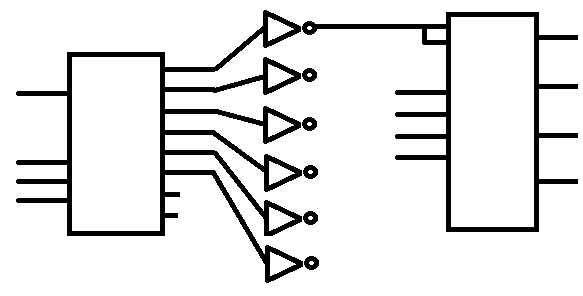
    The other trick is with hardware. Because the 328 is limited in the number of output lines available, I used a 74ls138 (3 to 8 decoder), tied to the Nano D4-D6 pins, then tied D7 to the enable pin to act as a switch. I routed the output line to an inverter (74ls04), then to the gate of a quad latch (74ls75). There is enough inverters in one chip to enable 6 of the quad latches. I then tied D8-D11 to the inputs of the latches. With a bit of simple code to drive the whole thing, 8 output lines becomes 24. Which is enough for 8 coils, 8 injectors, and a handful of idiot lights. All for pocket change.  The code for the latching operation is:

    /***************************************************************************************************
    
     History: [JAC] Original creation when the earth was cooling
    ***************************************************************************************************/
    #include "types.h"
    
    #define MAX_LATCH            32
    
    static const UByte lchMask[] = {
         0x01,0x02,0x04,0x08,0x11,0x12,0x14,0x18,0x21,0x22,0x24,0x28,0x31,0x32,0x34,0x38
        ,0x41,0x42,0x44,0x48,0x51,0x52,0x54,0x58,0x61,0x62,0x64,0x68,0x71,0x72,0x74,0x78
    };
    static UByte lch[8];
    void initLatches(void) {
        UByte c;
        DDRB &= 0xf0; DDRD &= 0x0f;
        for (c = 0; c < 8; c++) { lch[c] = 0; PORTB = 0; PORTD = c; PORTD = (PIND | 0x80); }
    }
    void setLatch(UByte n, bool t) {
        UByte a, b, c;
    
        if (n < MAX_LATCH) {
            b = lchMask[n] & 0x0f; a = lchMask[n] & 0x70; c = n / 4;
            lch[c] = t ? (lch[c] | b) : (lch[c] & ~b); PORTB = lch[c];
            PORTD = (PIND & 0x0f) | a; PORTD = (PIND | 0x80);
        }
    }
    bool isLatchOn(UByte n) {
        return (n < MAX_LATCH ? ((lch[n>>2] & (lchMask[n] & 0x0f)) != 0) : false);
    }
    /* end of file */

    Thats it for now

    Jack

    • Cancel
    • Vote Up +1 Vote Down
    • Sign in to reply
    • Cancel
  • jack.chaney56
    jack.chaney56 over 7 years ago

    Big one today as promised...


    First is types.h which hasn't changed particularly from the first. Just added some #define stuff at the end. There should be a device specific general .h file (usually the project name)

    /*************************************************************************************************** 
     All code provided is original and developed by Jack Chaney. Any similarity to code existing in 
     another location or form is purely coincidental. The code presented caries with it no guarantee 
     outside my statements that IT WORKED FOR ME. 
      
     If, in the future this code is used in any products, please provide proper recognition for my 
     efforts. 
      
     Jack Chaney, 2018 Chaney Firmware 
      
     This is the base include file, that pulls in all the AVR components, and standard items to make 
     life easier. I also declare some items for variable naming that makes it easier for me 
     to run on auto pilot.
     
     History: [JAC] Original creation when the earth was cooling 
    ***************************************************************************************************/  
    #ifndef _TYPES_H  
    #define _TYPES_H  
    #include <stdbool.h>  
    #include <stdio.h>  
    #include <avr/interrupt.h>  
    #include <avr/io.h>  
      
    typedef unsigned char  UByte;  
    typedef char           SByte;  
    typedef unsigned short UWord;  
    typedef short          SWord;  
    typedef unsigned long  ULong;  
    typedef long           SLong;  
      
    /* Hardware interfacers */  
    #define REG_B(a)      *((volatile UByte* const)(a))  
    #define REG_W(a)      *((volatile UWord* const)(a))  
    #define REG_L(a)      *((volatile ULong* const)(a))  
    #define REG_Bs(a)     *((volatile SByte* const)(a))  
    #define REG_Ws(a)     *((volatile SWord* const)(a))  
    #define REG_Ls(a)     *((volatile SLong* const)(a))  
    #define ARR_B(a)      ((UByte* const)(a))  
    #define ARR_W(a)      ((UWord* const)(a))  
    #define ARR_L(a)      ((ULong* const)(a))  
    #define ARR_Bs(a)     ((SByte* const)(a))  
    #define ARR_Ws(a)     ((SWord* const)(a))  
    #define ARR_Ls(a)     ((SLong* const)(a))  
      
    /* some use while(1) but I found this way compiles to fewer instructions */  
    #ifdef forever  
    #undef forever  
    #endif  
    #define forever    for(;;)  
      
    /* handy bits */  
    #define bit0    1  
    #define bit1    2  
    #define bit2    4  
    #define bit3    8  
    #define bit4    16  
    #define bit5    32  
    #define bit6    64  
    #define bit7    128  
    #define bit8    256  
    #define bit9    512  
    #define bit10    1024  
    #define bit11    2048  
    #define bit12    4096  
    #define bit13    8192  
    #define bit14    16384  
    #define bit15    32768  
      
    #define PART1    64L        /* part 1 of full circle for calculations */  
    #define PART2    512L       /* part 2 of full circle for calculations */  
    #define DEGS_PER_REV  (PART1*PART2)  
    #define TICS_PER_mS     2000  
    #define mS_PER_SEC      1000  
    #define SEC_PER_MIN     60  
    #define TICS_PER_MIN    (TICS_PER_mS*mS_PER_SEC*SEC_PER_MIN)  
    
    
    extern UWord etTkHi, etTkLo;  
    extern SWord dlyTkHi, dlyTkLo;  
    
    
    #endif  
    /* end of file */ 


    The second group are the files related to the hardware A2D.c

    /*************************************************************************************************** 
     All code provided is original and developed by Jack Chaney. Any similarity to code existing in 
     another location or form is purely coincidental. The code presented caries with it no guarantee 
     outside my statements that IT WORKED FOR ME. 
      
     If, in the future this code is used in any products, please provide proper recognition for my 
     efforts. 
      
     Jack Chaney, 2018 Chaney Firmware 
    
     History: [JAC] Original creation when the earth was cooling 
    ***************************************************************************************************/  
    #include "types.h"  
    #define ADCSRA_INIT   (7<<ADPS0)     /* Right aligned Free running /64 prescaler */  
    #define A2D_CHAN   8                 /* number of A/D channels */  
    #define A2D_FILTER   8               /* 8 to 1 filter */  
    #define A2D_HALF   (A2D_FILTER/2)    /* used for rounding the result */  
      
    static UByte a2dSemi4;               /* pseudo semaphore, are updates being done */  
    static SWord a2dVal[A2D_CHAN];  
    static UByte a2dChan;                /* current converting A/D */  
      
    SWord getA2d(UByte v) { return (v < A2D_CHAN ? ((a2dVal[v] + A2D_HALF) / A2D_FILTER) : 0); }  
      
    void initA2D(void) {  
     a2dSemi4 = 0;                       /* pseudo semaphore, to only run the conversions when ready */  
     for (a2dChan = 0; a2dChan < A2D_CHAN; a2dChan++) {  
      a2dVal[a2dChan] = 0;               /* clear the buffer */  
     }  
     ADCSRA = ADCSRA_INIT;               /* configure the A/D */  
    }  
    void rtUpdateA2D(void) {  
     if (a2dSemi4 == 0) {                /* don't run if semaphore is active(already running) */  
      a2dSemi4 = 1;                      /* started, so set the semaphore on */  
      a2dChan = 0;                       /* start with the first A/D */  
      ADMUX = a2dChan;                   /* set the A/D channel */  
      ADCSRA |= (1 << ADEN);             /* enable the A/D channel */  
      ADCSRA |= (1 << ADSC);             /* start the A/D conversion */  
      ADCSRA |= (1 << ADIE);             /* turn on the interrupt */  
     }  
    }  
    ISR(ADC_vect) {  
     SWord tmp = ADC;                    /* conversion complete, so fetch the A/D value */  
     ADCSRA &= ~(1<<ADEN);               /* disable the A/D while changing the MUX */  
    /* the filtering is a running average... remove one part and add in the new as replacement */  
     a2dVal[a2dChan] += tmp - (a2dVal[a2dChan] / A2D_FILTER);  
     a2dChan++;                          /* point to the next channel */  
     if (a2dChan < A2D_CHAN) {           /* check to see if all the channels are done */  
      ADMUX = a2dChan;                   /* set the A/D channel */  
      ADCSRA |= (1 << ADEN);             /* enable the A/D channel */  
      ADCSRA |= (1 << ADSC);             /* start the A/D conversion */  
     } else {  
      ADCSRA &= ~(1 << ADIE);            /* all the channels read, so turn off the interrupt */  
      a2dSemi4 = 0;                      /* and clear the interrupt */  
     }  
    }  
    /* end of file */


    UART.c

    /*************************************************************************************************** 
     All code provided is original and developed by Jack Chaney. Any similarity to code existing in 
     another location or form is purely coincidental. The code presented caries with it no guarantee 
     outside my statements that IT WORKED FOR ME. 
      
     If, in the future this code is used in any products, please provide proper recognition for my 
     efforts. 
      
     Jack Chaney, 2018 Chaney Firmware 
    
     History: [JAC] Original creation when the earth was cooling 
    ***************************************************************************************************/  
    #include "types.h"  
    #define UBAUD_57_6    34  
    #define UBAUD_38_4    51  
    #define UBAUD_19_2    103  
    #define UBAUD__9_6    207  
      
    #define BUFFSIZE      32  
      
    #define TXI0          (1<<TXCIE0)  
    #define UCSRA_INIT    (1<<U2X0)                           /* Timebase for UART 2x clock */  
    #define UCSRB_INIT    (1<<TXEN0)|(1<<RXEN0)|(1<<RXCIE0)   /* Enable transmit and receive lines and receive interrupt */  
    #define UCSRC_INIT    (3<<UCSZ00)|(0<<UPM00)|(0<<UMSEL00) /* n-8-1 */  
    #define COMMSPEED     UBAUD_19_2                          /* 19200 */  
      
    static UByte rxBuf[BUFFSIZE];  
    static UByte txBuf[BUFFSIZE];  
    static volatile UByte rxHed, rxTal, rxSiz;  
    static volatile UByte txHed, txTal, txSiz;  
      
    bool isComReady(void) { return (rxSiz != 0); }  
      
    void initUart(void) {  
     UCSR0A = UCSRA_INIT;  
     UCSR0B = UCSRB_INIT;  
     UCSR0C = UCSRC_INIT;  
     UBRR0 = COMMSPEED;  
     rxHed = 0; rxTal = 0; rxSiz = 0;  
     txHed = 0; txTal = 0; txSiz = 0;  
    }  
    /*==============================*/  
    /*       *** WARNING ***        */  
    /*  Do not use these functions  */  
    /*     within an interrupt      */  
    /*==============================*/  
    void putCom(UByte c) {  
     if ((UCSR0B & TXI0) == 0) {                              /* output buffer empty and no byte currently being sent */  
      UDR0 = c; UCSR0B |= TXI0;                               /* put byte in output port, and turn on the interrupt */  
     } else {  
      while (txSiz >= BUFFSIZE);                              /* make sure there is room in the buffer, or wait (see warning) */  
      cli();                                                  /* turn off interrupts, for safety */  
      txBuf[txTal] = c;                                       /* put the byte on the end of the buffer */  
      txTal = (txTal + 1) < BUFFSIZE ? txTal + 1 : 0;         /* adjust the pointer */  
      txSiz++;                                                /* increment the character counter */  
      sei();                                                  /* all done so turn the interrupts back on */  
     }  
    }  
    UByte getCom(void) {  
     UByte c = 0;  
     if (rxSiz > 0) {                                         /* if there isn't an input byte, just return 0 */  
      cli();                                                  /* turn off interrupts, for safety */  
      c = rxBuf[rxHed];                                       /* fetch the byte from the head of the buffer */  
      rxHed = (rxHed + 1) < BUFFSIZE ? rxHed + 1 : 0;         /* adjust the pointer */  
      --rxSiz;                                                /* decrement the character counter */  
      sei();                                                  /* all done so turn the interrupts back on */  
     }  
     return c;  
    }  
    /*==============================*/  
    ISR(USART_RX_vect) {                                      /* interestingly, the interrupt looks just like the runtime */  
     UByte c = UDR0;                                          /* fetch the byte from the input port */  
     if (rxSiz < BUFFSIZE) {                                  /* make sure there is room in the buffer, but because it is the interrupt, can't wait */  
      cli();                                                  /* block the other interrupts, for safety */  
      rxBuf[rxTal] = c;                                       /* put the byte on the end of the buffer */  
      rxTal = (rxTal + 1) < BUFFSIZE ? rxTal + 1 : 0;         /* adjust the pointer */  
      rxSiz++;                                                /* increment the character counter */  
      sei();                                                  /* all done so turn the interrupts back on */  
     } else { /* Dropped bytes go here */ }  
    }  
    ISR(USART_TX_vect) {                                      /* this could nearly be a cut and paste, but the buffer names are swapped */  
     UByte c;  
     if (txSiz > 0) {                                         /* special case for last one out */  
      cli();                                                  /* block the other interrupts, for safety */  
      c = txBuf[txHed];                                       /* fetch the byte from the head of the buffer */  
      txHed = (txHed + 1) < BUFFSIZE ? txHed + 1 : 0;         /* adjust the pointer */  
      --txSiz; UDR0 = c;                                      /* decrement the character counter, and put the byte in the output port */  
      sei();                                                  /* all done so turn the interrupts back on */  
     } else {  
      UCSR0B &= ~TXI0;                                        /* last byte out, disable the interrupt */
     } 
    } 
    /* end of file */


    EEPROM.c

    /*************************************************************************************************** 
     All code provided is original and developed by Jack Chaney. Any similarity to code existing in 
     another location or form is purely coincidental. The code presented caries with it no guarantee 
     outside my statements that IT WORKED FOR ME. 
      
     If, in the future this code is used in any products, please provide proper recognition for my 
     efforts. 
      
     Jack Chaney, 2018 Chaney Firmware 
    
     History: [JAC] Original creation when the earth was cooling 
    ***************************************************************************************************/  
    #include "types.h"  
      
    UByte getEEPROM(UWord ofs) {  
     UByte rVal = 255;  
     if (ofs <= E2END) {  
      while(EECR & (1 << EEPE)); EEAR = ofs;  
      EECR |= (1 << EERE); rVal = EEDR;  
     }  
     return rVal;  
    }  
    void putEEPROM(UWord ofs, UByte d) {  
     if (ofs <= E2END) {  
      while(EECR & (1 << EEPE)); EEAR = ofs;  
      EEDR = d; EECR |= (1 << EEMPE); EECR |= (1 << EEPE);  
     }  
    }  
    /* end of file */


    and the file that bridges the gap TIMERS.c

    /*************************************************************************************************** 
     All code provided is original and developed by Jack Chaney. Any similarity to code existing in 
     another location or form is purely coincidental. The code presented caries with it no guarantee 
     outside my statements that IT WORKED FOR ME. 
      
     If, in the future this code is used in any products, please provide proper recognition for my 
     efforts. 
      
     Jack Chaney, 2018 Chaney Firmware 
     
     History: [JAC] Original creation when the earth was cooling 
    ***************************************************************************************************/  
    #include "types.h"  
      
    #define TIMSK0_INIT  (1<<OCIE0A)  
    #define TIMSK2_INIT  0  
    #define TIMSK1_INIT  (1<<TOIE1)  
    #define TCCR0A_INIT  0  
    #define TCCR0B_INIT  (3<<CS00)  
    #define TCCR2A_INIT  0  
    #define TCCR2B_INIT  (3<<CS00)  
    #define TCCR1A_INIT  0  
    #define TCCR1B_INIT  (2<<CS10)  
    #define TCCR1C_INIT  0  
      
    #define mS_UPDATE_8  250  
    void setTach(bool);
      
    SLong ov0Tic;  
    SLong ov2Tic;  
    SLong ov1Tic;  
    SLong getTime1(void) { ULong rVal; cli(); rVal = (ov1Tic | TCNT1); sei(); return rVal; }  
      
    void initTimers(void) {  
     TCCR0A = TCCR0A_INIT; TCCR0B = TCCR0B_INIT; TIMSK0 = TIMSK0_INIT;  
     TCCR2A = TCCR2A_INIT; TCCR2B = TCCR2B_INIT; TIMSK2 = TIMSK2_INIT;  
     TCCR1A = TCCR1A_INIT; TCCR1B = TCCR1B_INIT; TCCR1C = TCCR1C_INIT; TIMSK1 = TIMSK1_INIT;  
    }  
    ISR(TIMER0_COMPA_vect) {  
      OCR0A += mS_UPDATE_8;  /* refresh for 1mS Timer Tic */  
      if (dlyTkHi > 0) { --dlyTkHi; if (dlyTkHi == 0) { OCR1A = etTkHi; TIMSK1 |= (1 << OCIE1A); } }  
      if (dlyTkLo > 0) { --dlyTkLo; if (dlyTkLo == 0) { OCR1B = etTkLo; TIMSK1 |= (1 << OCIE1B); } }  
    }  
    ISR(TIMER0_OVF_vect) { ov0Tic = (ov0Tic +   256L) & 0x07ffff00; } 
     
    ISR(TIMER2_COMPA_vect) { TIMSK2 &= ~(1 << OCIE2A); setTach(true); }  
    ISR(TIMER2_COMPB_vect) { TIMSK2 &= ~(1 << OCIE2B); setTach(false); }  
    ISR(TIMER2_OVF_vect) {  
        ov2Tic = (ov2Tic +   256L) & 0x07ffff00;  
        if ((ov2Tic == dlyTkHi) && (tkHi == 1)) { /* timer match and flag on */  
          tkHi = 0;                               /* condition met, so turn off flag */  
          if (etTkHi > 0) {                       /* special condition if low order portion is 0 */  
            OCR2A = etTkHi; TIMSK2 |= (1 << OCIE2A); /* everything regular, so just like the 16 bit */  
          } else {                                /* if short portion is 0 the event is now */  
            setTach(true);                        /* tach on */  
          }  
        }  
        if ((ov2Tic == dlyTkLo) && (tkLo == 1)) { /* timer match and flag on */  
          tkLo = 0;                               /* condition met, so turn off flag */  
          if (etTkLo > 0) {                       /* everything else the same */  
            OCR2B = etTkHi; TIMSK2 |= (1 << OCIE2B);  
          } else {  
            setTach(false);                      /* tach on */  
          }  
        }  
    }   
    ISR(TIMER1_OVF_vect) { ov1Tic = (ov1Tic + 65536L) & 0x3fff0000; }  
    /************************************************************************************************** 
     Timer 1 is a 16 bit timer running fast 
     Timer 1 group is used for coil action A on B off 
     Activity for both is to perform the operation and disable the interrupt 
    **************************************************************************************************/  
    ISR(TIMER1_COMPA_vect) { TIMSK1 &= ~(1 << OCIE1A); setTach(true);  }  
    ISR(TIMER1_COMPB_vect) { TIMSK1 &= ~(1 << OCIE1B); setTach(false); }  
    /* end of file */ 


    The tach signal is used twice in the timer, because we haven't covered ignition or fueling only event timing. So the next file is the SCHEDULER.c

    /*************************************************************************************************** 
     All code provided is original and developed by Jack Chaney. Any similarity to code existing in 
     another location or form is purely coincidental. The code presented caries with it no guarantee 
     outside my statements that IT WORKED FOR ME. 
      
     If, in the future this code is used in any products, please provide proper recognition for my 
     efforts. 
      
     Jack Chaney, 2018 Chaney Firmware 
    
     History: [JAC] Original creation when the earth was cooling 
    ***************************************************************************************************/  
    #include "types.h"  
    UWord etTkHi, etTkLo;  
    SWord dlyTkHi, dlyTkLo;  
      
    /************************************************************************************************** 
    Generated TACH signal 
    **************************************************************************************************/  
    void ignTkHi(SLong et, SLong bt) {  
        SLong ev = (et + bt + 4) >> 3;  
      
        etTkHi = (UByte)(ev & 0xff);  
        dlyTkHi = ev & 0x07ffff00;  
        tkHi = 1;  
    }  
    void ignTkLo(SLong et, SLong bt) {  
        SLong ev = (et + bt + 4) >> 3;  
      
        etTkLo = (UByte)(ev & 0xff);  
        dlyTkLo = ev & 0x07ffff00;  
        tkLo = 1;  
    }  
    /************************************************************************************************** 
    Generated TACH signal first version high speed timer
    **************************************************************************************************/  
    //void ignTkHi(SLong et, SLong bt) {  
    // SLong ev = et + bt;               /* get the timer event compare value */  
    //  
    // etTkHi = (UWord)(ev & 0xffff);    /* the value is masked to 16 bits to match the compare register */  
    // if (et > THREE_mS) {              /* check for long delay and set 1ms timeout */  
    //  dlyTkHi = (SWord)((et - TWO_mS) / TICS_PER_mS);  
    // } else {                          /* no delay */  
    //  OCR1A = etTkHi;                  /* set the timer compare register */  
    //  TIMSK1 |= (1 << OCIE1A);         /* and enable the interrupt */  
    // }  
    //}  
    //void ignTkLo(SLong et, SLong bt) {  
    // SLong ev = et + bt;               /* get the timer event compare value */  
    //  
    // etTkLo = (UWord)(ev & 0xffff);    /* the value is masked to 16 bits to match the compare register */  
    // if (et > THREE_mS) {              /* check for long delay and set 1ms timeout */  
    //  dlyTkLo = (SWord)((et - TWO_mS) / TICS_PER_mS);  
    // } else {                          /* no delay */  
    //  OCR1B = etTkLo;                  /* set the timer compare register */  
    //  TIMSK1 |= (1 << OCIE1B);         /* and enable the interrupt */  
    // }  
    //}  
    /************************************************************************************************** 
    Parameters: 
       min/max - start and end angle of window for sample 
       pa - angle of last event, last tooth 
       bs - magic BASE 
       tm - time of last event, last tooth 
    **************************************************************************************************/  
    void schedule(UWord min, UWord max, UWord pa, SLong bs, SLong tm) {  
     SLong ft;  
     UByte c;  
      
     if (min < max) {  
      for (c = 0; c < cylCt; c++) {  
       if ((min < tkSt[c]) && (tkSt[c] <= max)) { ft = (SLong)(tkSt[c] - pa) * bs / PART2; ignTkHi(ft, tm); }  
       if ((min < tkEv[c]) && (tkEv[c] <= max)) { ft = (SLong)(tkEv[c] - pa) * bs / PART2; ignTkLo(ft, tm); }  
     } else {  
      for (c = 0; c < spEvnt; c++) {  
       if ((min < tkSt[c]) || (tkSt[c] <= max)) { ft = (SLong)(tkSt[c] - pa) * bs / PART2; ignTkHi(ft, tm); }  
       if ((min < tkEv[c]) || (tkEv[c] <= max)) { ft = (SLong)(tkEv[c] - pa) * bs / PART2; ignTkLo(ft, tm); }  
     }  
    }
    /* end of file */


    The latching file LATCHES.c handles the special hardware with the latching chips.

    /*************************************************************************************************** 
     All code provided is original and developed by Jack Chaney. Any similarity to code existing in 
     another location or form is purely coincidental. The code presented caries with it no guarantee 
     outside my statements that IT WORKED FOR ME. 
      
     If, in the future this code is used in any products, please provide proper recognition for my 
     efforts. 
      
     Jack Chaney, 2018 Chaney Firmware 
    
     History: [JAC] Original creation when the earth was cooling 
    ***************************************************************************************************/  
    #include "types.h"  
      
    #define MAX_LATCH            32  
      
    static const UByte lchMask[] = {  
         0x01,0x02,0x04,0x08,0x11,0x12,0x14,0x18,0x21,0x22,0x24,0x28,0x31,0x32,0x34,0x38  
        ,0x41,0x42,0x44,0x48,0x51,0x52,0x54,0x58,0x61,0x62,0x64,0x68,0x71,0x72,0x74,0x78  
    };  
    static UByte lch[8];  
    void initLatches(void) {  
        UByte c;  
        DDRB &= 0xf0; DDRD &= 0x0f;  
        for (c = 0; c < 8; c++) { lch[c] = 0; PORTB = 0; PORTD = c; PORTD = (PIND | 0x80); }  
    }  
    void setLatch(UByte n, bool t) {  
        UByte a, b, c;  
      
        if (n < MAX_LATCH) {  
            b = lchMask[n] & 0x0f; a = lchMask[n] & 0x70; c = n / 4;  
            lch[c] = t ? (lch[c] | b) : (lch[c] & ~b); PORTB = lch[c];  
            PORTD = (PIND & 0x0f) | a; PORTD = (PIND | 0x80);  
        }  
    }  
    bool isLatchOn(UByte n) {  
        return (n < MAX_LATCH ? ((lch[n>>2] & (lchMask[n] & 0x0f)) != 0) : false);  
    }  
    /* end of file */


    and last, the input manager for cam and crank signals IGNCAMCRK.c

    /*************************************************************************************************** 
     All code provided is original and developed by Jack Chaney. Any similarity to code existing in 
     another location or form is purely coincidental. The code presented caries with it no guarantee 
     outside my statements that IT WORKED FOR ME. 
      
     If, in the future this code is used in any products, please provide proper recognition for my 
     efforts. 
      
     Jack Chaney, 2018 Chaney Firmware 
     
     History: [JAC] Original creation when the earth was cooling 
    ***************************************************************************************************/  
      
    #include "types.h"  
      
    #define EICRA_INIT   (1<<ISC00)|(1<<ISC10) /* Trigger INT0 and INT1 on either edge */  
    #define EIMSK_INIT   (1<<INT0)|(1<<INT1)   /* Set INT0 and INT1 active */  
    #define QUART_SEC     250                  /* provide a 250 mS timeout 1/4 second */
      
    /* Calibration value in future, but for now just provide constants */  
    SWord getCrankToothCt(void) { return 4; }  
    SWord getCylCount(void) { return 4; }
    SWord getCylAngle(UByte) { return (16384*c); }
    
    bool isCrkRising(void) { return false; } /* these are future calibration values, but for now force the false falling edge */  
    bool isCamRising(void) { return false; }  
    bool isInt0Low(void) { return ((PIND & (1<<PD2)) != 0); }  
    bool isInt1Low(void) { return ((PIND & (1<<PD3)) != 0); }  
      
    SLong crkTime;  
    SLong crkDiff;  
    SLong camTIme;  
    SLong camDiff;  
      
    SWord teeth;  
    SWord rpm;  
    SWord preRpm;  
    UWord camAngle;
    UByte camError;
    UWord toothAngle;
    UByte toothError;
    UByte tmOut;
      
    void initIgn(void) {  
     EICRA = EICRA_INIT;  
     EIMSK = EIMSK_INIT;  
     crkTime = camTime = 0;  
     toothAfterCam = 0;  
     tmOut = 0;
    }  
    void rtUpdateIgn(void) {  
     if (tmOut > 0) {  
      --tmOut;  
      rpm = preRpm / crkDiff;  
     } else {  
      teeth = getCrankToothCt();  
      preRpm = TICS_PER_MIN / teeth;
      toothAngle = DEG_PER_REV / teeth;  
      toothError = DEG_PER_REV % teeth;
      cylCt = (UByte)getCylCount();  
      for (c = 0; c < cylCt; c++) {  
        tkEv[c] = getCylAngle(c);  
        tkSt[c] = tkEv[c] - FIVE_DEG;  
      }  
     }  
    }  
    /************************************************************************************************** 
     Crank interrupt 
     Interrupt is called on both rising and falling edges of crank signal. 
     - Active edge is defined as falling edge, or rising edge 
        Active edge is determined as falling and signal low, or rising and signal high. 
     - Primary activity for the interrupt is to determine angular velocity and cam angle 
       Using high speed clock timer, obtain current time as tempTime 
       and using previous time (crkTime) calculate a difference between active signals. 
     - Preserve time and difference as crkTime and crkDiff 
    **************************************************************************************************/  
    ISR(INT0_vect) {  
     SLong tmpTime = getTime1();  
     SLong tmpDiff = tmpTime + (tmpTime > crkTime ? 0 : 0x40000000) - crkTime;  
    /************************************************************************************************** 
     Because the timer has a limit of a max value before rollover, the 32 bit number is limited 
     to only using 30 bits before rollover. At rollover occurrence a factor is added to retain 
     the proper value for DIFF. TIME is unaffected. 
    **************************************************************************************************/  
     if (isInt0Low() ^ isCrkRising()) {  
    /************************************************************************************************** 
      use the cam signal to locate the tooth 
    **************************************************************************************************/  
      tmOut = QUART_SEC;  
      camAngle += toothAngle;  
      camError += toothError; if (toothError >= teeth) { camAngle++; camError -= teeth; }  
      if (isCamDet()) {  
       setCamDet(false); /* cam detected so clear the flag */  
       camAngle = 0;  
       camError = 0;
      }  
      crkTime = tmpTime;  
      crkDiff = tmpDiff;  
    /* this doesn't provide correction for partial error correction */  
      min = camAngle + (toothAngle / 2);  
      max = min + toothAngle;  
    /* this is actually a good place to invoke the scheduler, as long as it isn't */  
    /* called to do too much in its operation. */  
     }  
    }  
    /************************************************************************************************** 
     Cam interrupt 
    **************************************************************************************************/  
    ISR(INT1_vect) {  
     SLong tmpTime = getTime1();  
     SLong tmpDiff = tmpTime + (tmpTime > crkTime ? 0 : 0x40000000) - camTime;  
     if (isInt1Low() ^ isCamRising()) {  
      setCamDet(true); /* simple signal for now */  
      camTime = tmpTime;  
      camDiff = tmpDiff;  
     }  
    }  
    /* end of file */ 


    That should catch things up for now, I think I got everything, Probably should have run a compile on all this stuff to make sure, but what fun would that be. Besides, if there is something wrong, then it gives an opportunity to get questions. Otherwise, I give my 100% guarantee. it either will work or it won't. I guess the setTach() call isn't attached to anything at the moment.


    Jack

    • Cancel
    • Vote Up +1 Vote Down
    • Sign in to reply
    • Cancel
  • jack.chaney56
    jack.chaney56 over 7 years ago

    I was going to run the code when I got home from my real job. Then, I started setting up my bench, connecting up all the parts, and plugging in the power, sat back in my chair, and blinked. Three hours later, my wife told me I would probably be more comfortable sleeping in bed.  So, I didn't get a chance to compile all this stuff, and I don't have my bench set up here at work. I can provide a few extras in order to move things along, like circuits. People here seem to like circuits.


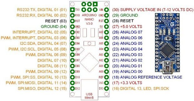
    The Nano has a bunch of pins to connect the 328 to the outside world.

    image

    I am not an Electrical Engineer, but I have had a lot of experience dealing with circuits and circuit design (mostly at the logic level), and things I throw together on a breadboard tend to work, so please understand any circuits I provide, would do well to have a serious design overview performed.


    image

    With that in mind... the Nano has two sets of connecters on either side of the board. One side is primarily the A/Ds, and the other side is listed as D0 - D13. For the project, the D0 and D1 will remain reserved for serial communication (works through the USB), D2 and D3 will be the interrupt inputs for crank and cam signals (this will be circuit 1). D4 through D11 will operate the output latches (this will be circuit 2). The analog lines are tricky, and open to all sorts of opinion, so I will offer a simple solution, and let people with more knowledge make comment (circuit 3).


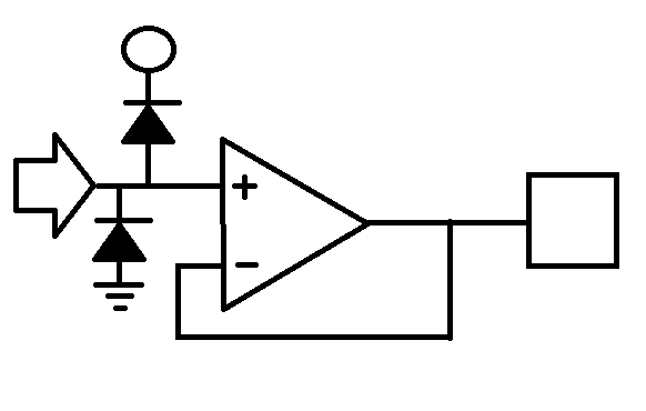
    Circuit 1: The circle is for 12v Vbatt (should have a resistor to regulate. The arrow is the crank or cam signal (same circuit for both). The box is the line that goes to either D2 or D3 depending. The IC is just a simple comparator (like an LM2903).

    image

    Circuit 2: The box on the left is a 74ls138, the input lines go from top to bottom D7 (enable), D4 (A0), D5 (A1), and D6 (A2). The outputs route through a 74ls04 hex inverter. The inverter connects to the enable 1&2 and enable 3&4 of the 75ls75 (one of 6 shown). The other inputs of the 74ls75 are connected to D8 (1D), D9 (2D), D10 (3D), and D11 (4D). The D8-D11 connect the same to all 6 of the 74ls75 ICs. If you would like, you can add another 04 and two more 75s and have 32 output lines, but 24 is satisfactory for this application.

    image

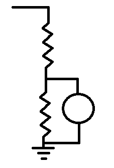
    Circuit 3: Analog lines are all similar and only need to provide a simple divider. The sensors that are attached are the governing elements here. The simple divider is shown. Where the circle represents some sort of variable resistance sensor, and the line on the left attaches to the A/D input. Though looking at this, it probably needs a pull up resistor someplace. Again, just a play circuit for now.

    image

    • Cancel
    • Vote Up +2 Vote Down
    • Sign in to reply
    • Cancel
  • jack.chaney56
    jack.chaney56 over 7 years ago

    My favorite word errata.  I had the chance to compile the code, and found a few "undocumented features" (bugs) in what I posted. The good news is half the files are clean.

    A2D.c

    EEPROM.c

    LATCHES.c

    and UART.c

    The main issue with stuff was undeclared variables and constants, so start at the top.

    types.h

    line 71 should be DEG_PER_REV not DEGS_PER_REV

    line 73-75 should be declared as long so add an 'L' to the end of the numbers

    ...additions.  Because the variables are shared globally for now, need to add to the extern list

    extern UByte tkHi, tkLo;

    extern UByte cylCt;

    extern UWord tkEv[];

    extern UWord tkSt[];


    TIMERS.c

    Like I said, setTach needed to be defined, so make a call to access one of the latches.

    void setLatch(UByte, bool);

    void setTach(bool t) { setLatch(23, t); }


    IGNCRKCAM.c

    This one had a lot of things missing, mostly What I think of as loop closing stuff.

    add line #define FIVE_DEG  466

    add prototype SLong getTime1(void);

    line 34: correct spelling SLong camTime not SLong camTIme

    add some variables

         UByte cylCt;

         UWord tkEv[8];

         UWord tkSt[8];

    add a switch detection for cam detected

         UByte camDet = 0;

         bool isCamDet(void) { return (camDet != 0); }

         void setCamDet(bool t) { camDet = t ? 1 : 0; }

    line 50 remove toothAfterCam = 0; (just used for first example).

    declare variable in rtUpdateIgn routine

         UByte c;

    declare variables in INT(INT0_vect)

         UWord min, max;


    SCHEDULER.c

    missed some stuff due to not correcting the copy paste stuff

    add variables UByte tkHi, tkLo;

    in schedule(...) near line 73 the for loops were missing the closing bracket '}'

    also closing bracket for second for loop.

    The variable name in the second for loop should be cylCt (copy paset error)


    ...and for some reason when writing a C program it is necessary to have a main function, but I didn't really provide one.

    #include "types.h"
    void initIgn(void);
    void initA2D(void);
    void initLatches(void);
    void initTimers(void);
    void initUart(void);
    int main(void) {
     initA2D();
     initLatches();
     initTimers();
     initUart();
     initIgn();
     forever { }
     return 0;
    }


    Something will go in the forever loop, in a bit, or you can plug in your own ideas in the meantime.


    (sloppy) Jack

    • Cancel
    • Vote Up +1 Vote Down
    • Sign in to reply
    • Cancel
  • jack.chaney56
    jack.chaney56 over 7 years ago in reply to jack.chaney56

    Always one more thing... In the 1mS timer operation there needs to be calls to update the A/Ds and invoke the ignition, both are the rtUpdate routines

    rtUpdateA2D();

    rtUpdateIgn();


    Jack

    • Cancel
    • Vote Up +1 Vote Down
    • Sign in to reply
    • Cancel
<>
element14 Community

element14 is the first online community specifically for engineers. Connect with your peers and get expert answers to your questions.

  • Members
  • Learn
  • Technologies
  • Challenges & Projects
  • Products
  • Store
  • About Us
  • Feedback & Support
  • FAQs
  • Terms of Use
  • Privacy Policy
  • Legal and Copyright Notices
  • Sitemap
  • Cookies

An Avnet Company © 2025 Premier Farnell Limited. All Rights Reserved.

Premier Farnell Ltd, registered in England and Wales (no 00876412), registered office: Farnell House, Forge Lane, Leeds LS12 2NE.

ICP 备案号 10220084.

Follow element14

  • X
  • Facebook
  • linkedin
  • YouTube