Hello all.
I was wondering where/how Ben connected the display to the Raspberry Pi. I've been trying to figure it out by watching the video but can't quiet figure it out.
Also, would I be able to connect a display to the B+ the same way.
Thanks all.
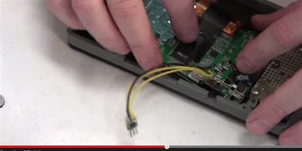
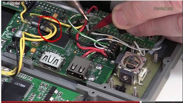
Hello all.
I was wondering where/how Ben connected the display to the Raspberry Pi. I've been trying to figure it out by watching the video but can't quiet figure it out.
Also, would I be able to connect a display to the B+ the same way.
Thanks all.