element14 Community
element14 Community
    Register Log In
  • Site
  • Search
  • Log In Register
  • Community Hub
    Community Hub
    • What's New on element14
    • Feedback and Support
    • Benefits of Membership
    • Personal Blogs
    • Members Area
    • Achievement Levels
  • Learn
    Learn
    • Ask an Expert
    • eBooks
    • element14 presents
    • Learning Center
    • Tech Spotlight
    • STEM Academy
    • Webinars, Training and Events
    • Learning Groups
  • Technologies
    Technologies
    • 3D Printing
    • FPGA
    • Industrial Automation
    • Internet of Things
    • Power & Energy
    • Sensors
    • Technology Groups
  • Challenges & Projects
    Challenges & Projects
    • Design Challenges
    • element14 presents Projects
    • Project14
    • Arduino Projects
    • Raspberry Pi Projects
    • Project Groups
  • Products
    Products
    • Arduino
    • Avnet Boards Community
    • Dev Tools
    • Manufacturers
    • Multicomp Pro
    • Product Groups
    • Raspberry Pi
    • RoadTests & Reviews
  • Store
    Store
    • Visit Your Store
    • Choose another store...
      • Europe
      •  Austria (German)
      •  Belgium (Dutch, French)
      •  Bulgaria (Bulgarian)
      •  Czech Republic (Czech)
      •  Denmark (Danish)
      •  Estonia (Estonian)
      •  Finland (Finnish)
      •  France (French)
      •  Germany (German)
      •  Hungary (Hungarian)
      •  Ireland
      •  Israel
      •  Italy (Italian)
      •  Latvia (Latvian)
      •  
      •  Lithuania (Lithuanian)
      •  Netherlands (Dutch)
      •  Norway (Norwegian)
      •  Poland (Polish)
      •  Portugal (Portuguese)
      •  Romania (Romanian)
      •  Russia (Russian)
      •  Slovakia (Slovak)
      •  Slovenia (Slovenian)
      •  Spain (Spanish)
      •  Sweden (Swedish)
      •  Switzerland(German, French)
      •  Turkey (Turkish)
      •  United Kingdom
      • Asia Pacific
      •  Australia
      •  China
      •  Hong Kong
      •  India
      •  Korea (Korean)
      •  Malaysia
      •  New Zealand
      •  Philippines
      •  Singapore
      •  Taiwan
      •  Thailand (Thai)
      • Americas
      •  Brazil (Portuguese)
      •  Canada
      •  Mexico (Spanish)
      •  United States
      Can't find the country/region you're looking for? Visit our export site or find a local distributor.
  • Translate
  • Profile
  • Settings
element14's The Ben Heck Show
  • Challenges & Projects
  • element14 presents
  • element14's The Ben Heck Show
  • More
  • Cancel
element14's The Ben Heck Show
Forum Help: Raspberry Pi with a Portable TV as a screen?
  • Blog
  • Forum
  • Documents
  • Polls
  • Files
  • Members
  • Mentions
  • Sub-Groups
  • Tags
  • More
  • Cancel
  • New
Join element14's The Ben Heck Show to participate - click to join for free!
Actions
  • Share
  • More
  • Cancel
Forum Thread Details
  • State Suggested Answer
  • Replies 8 replies
  • Answers 1 answer
  • Subscribers 30 subscribers
  • Views 811 views
  • Users 0 members are here
  • composite
  • tv
  • mod
  • raspberry
  • help
  • hack
  • portable
  • pi
  • project
  • video
  • show
  • challenge
  • heck
  • ben
Related

Help: Raspberry Pi with a Portable TV as a screen?

RovertScott
RovertScott over 9 years ago

Hey Ben,


I'm trying to find a way to add composite video to an old OPTIMUS portable LCD TV for a Raspberry Pi project, but information is scarce.

Then I found out you used to use them on old portable game console hacks.

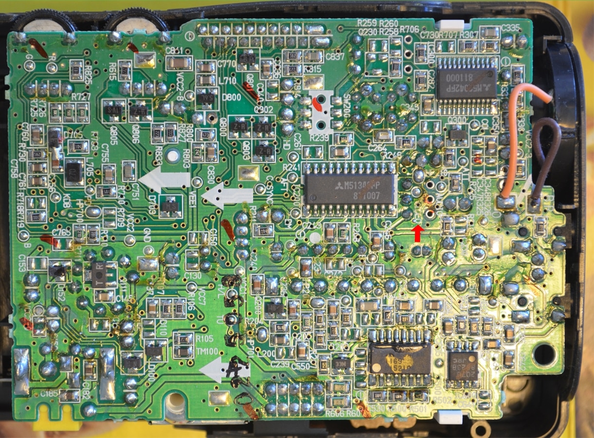
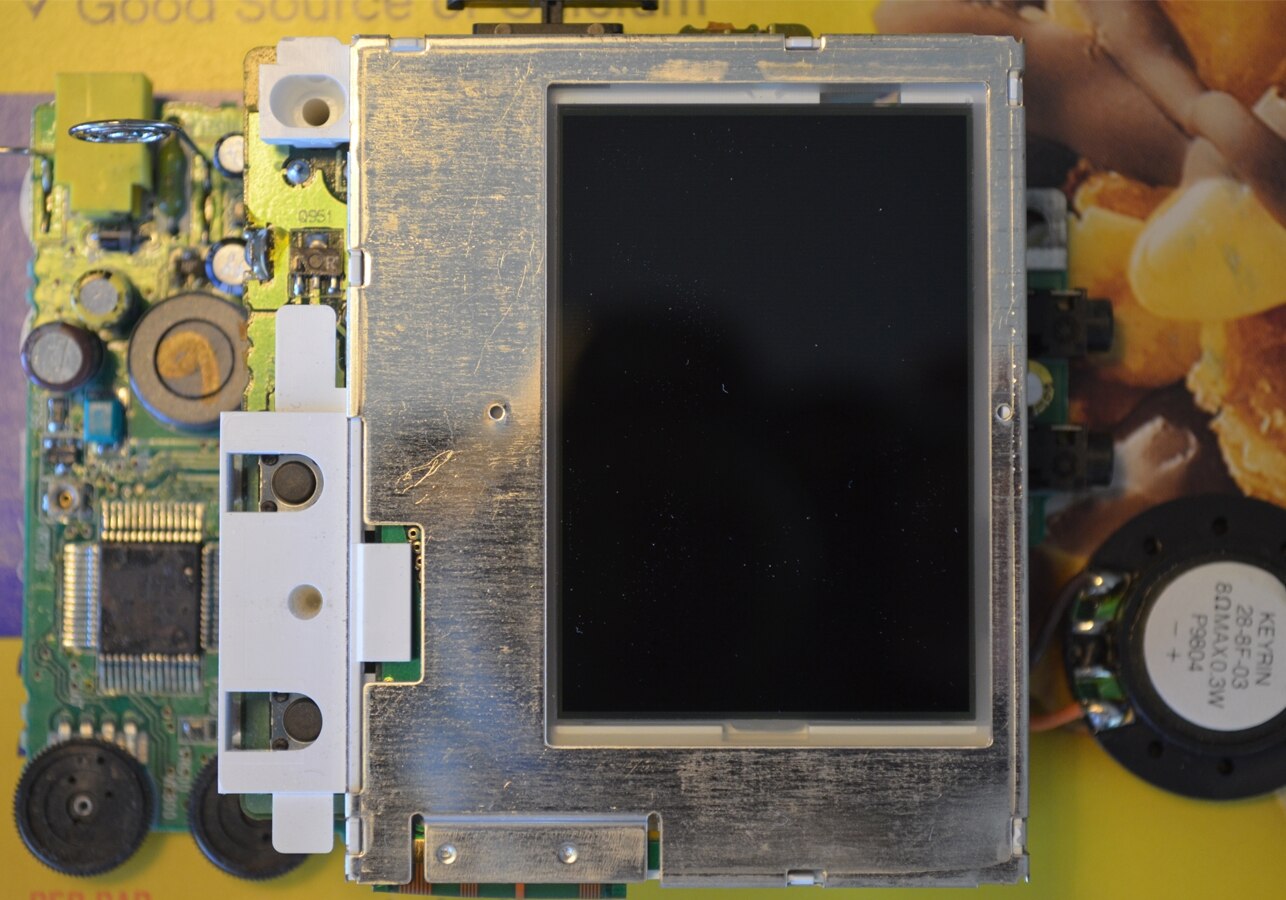
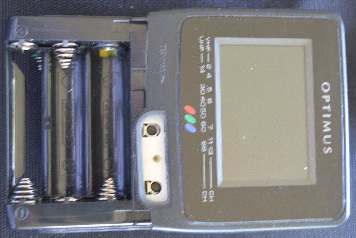
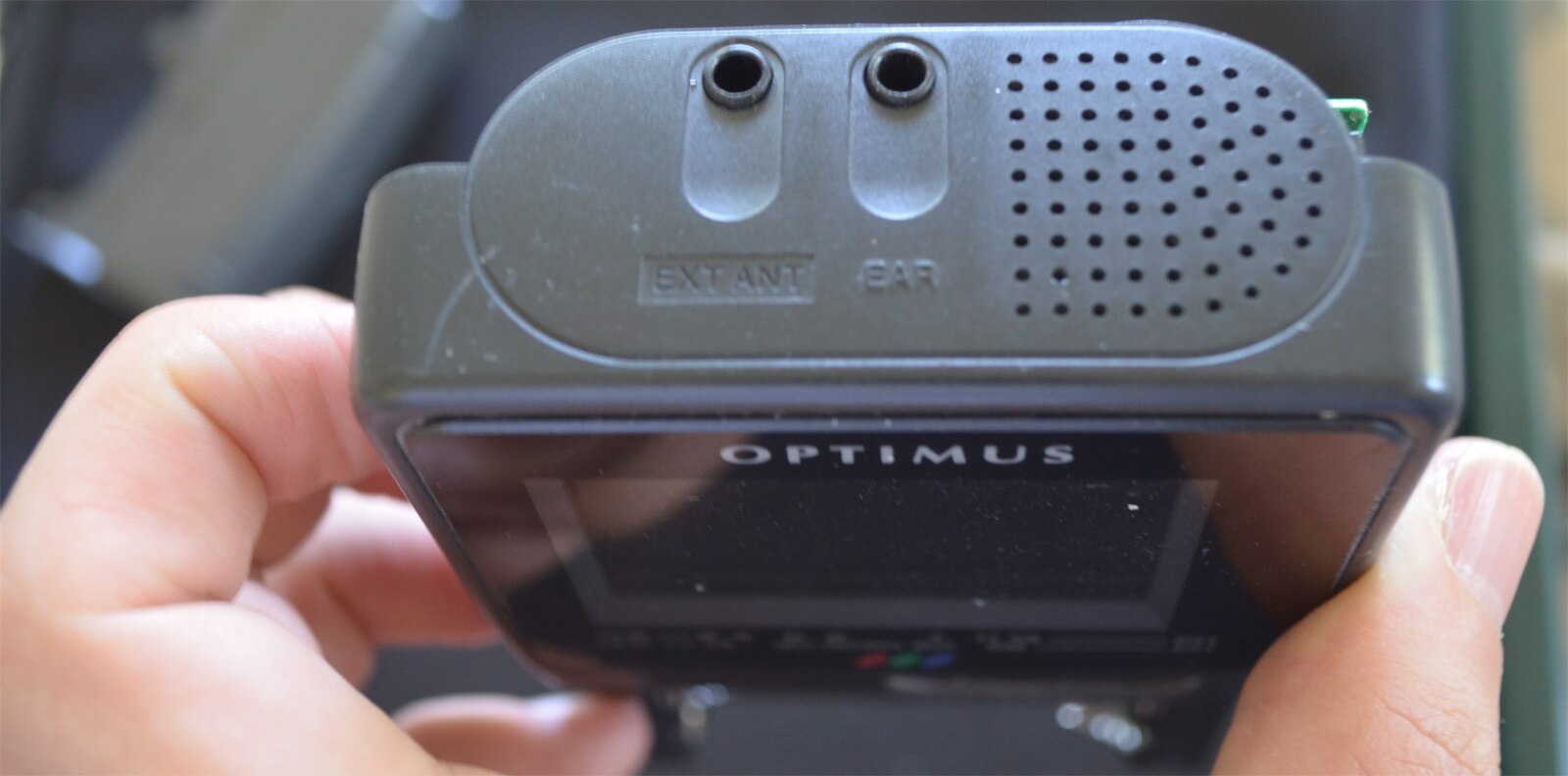
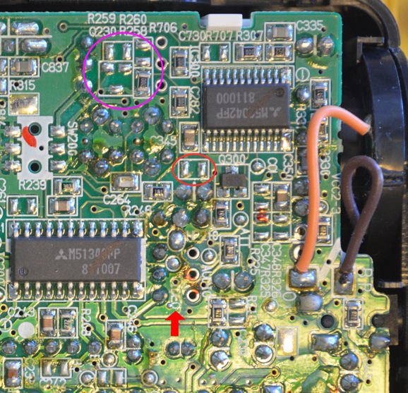
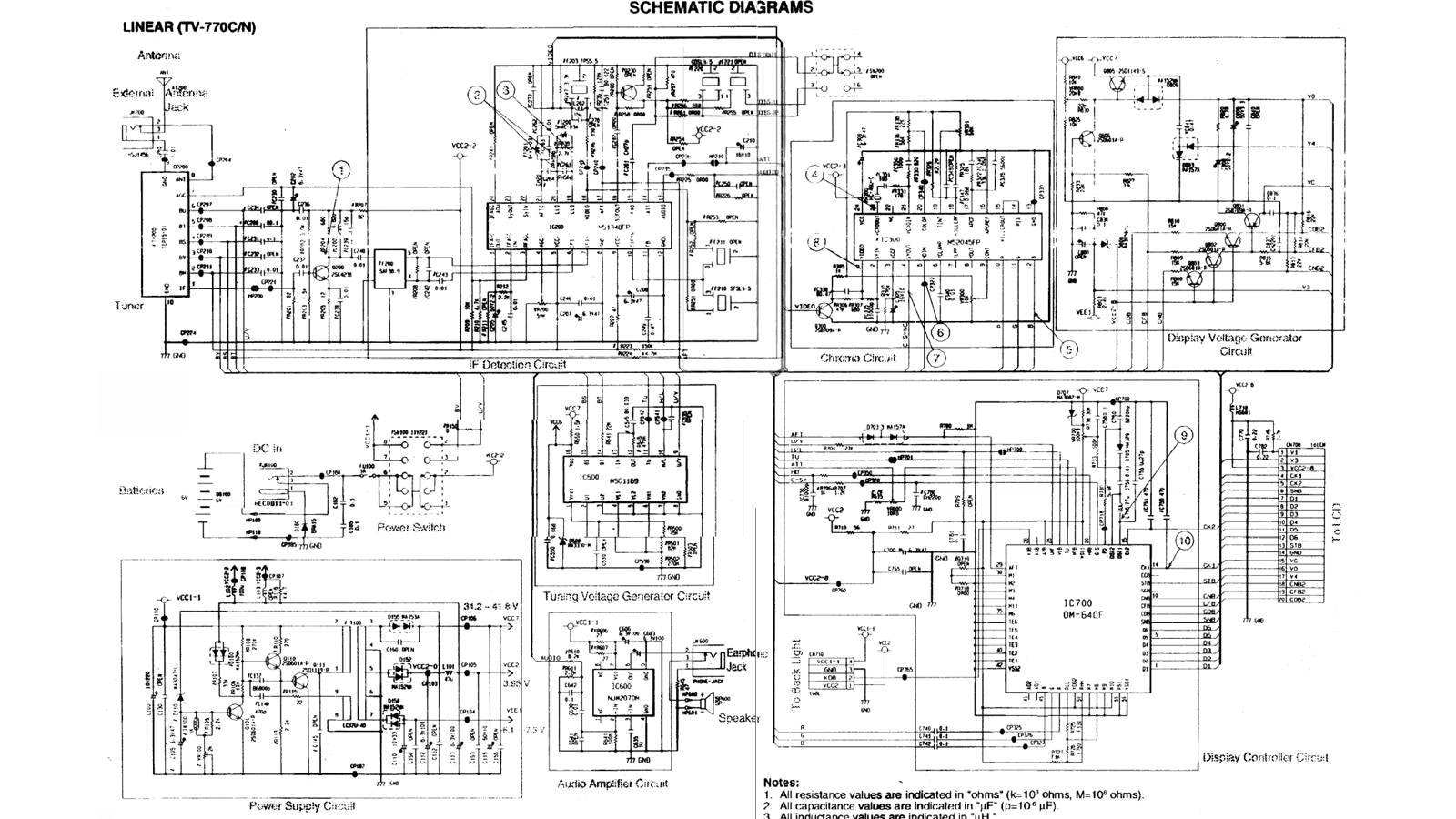
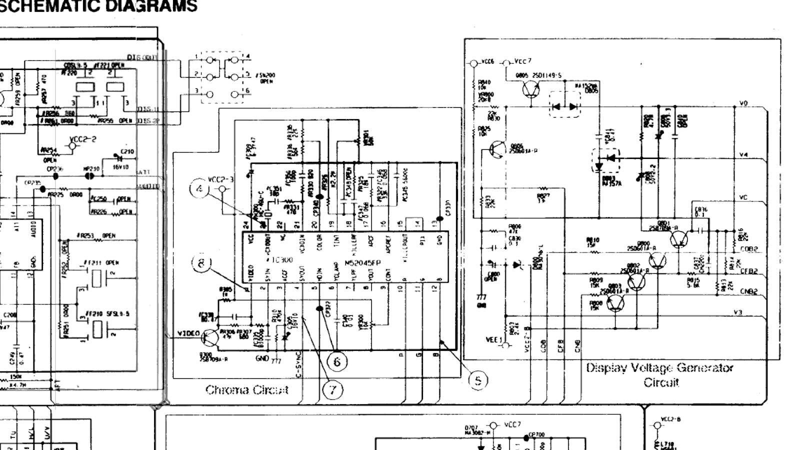
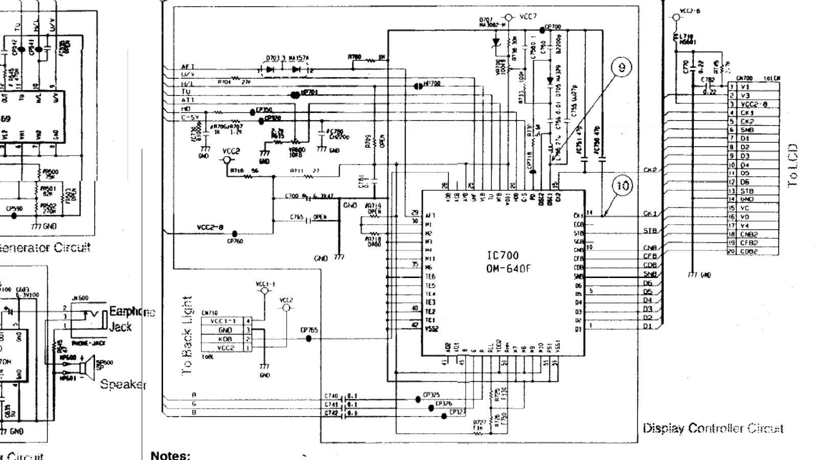
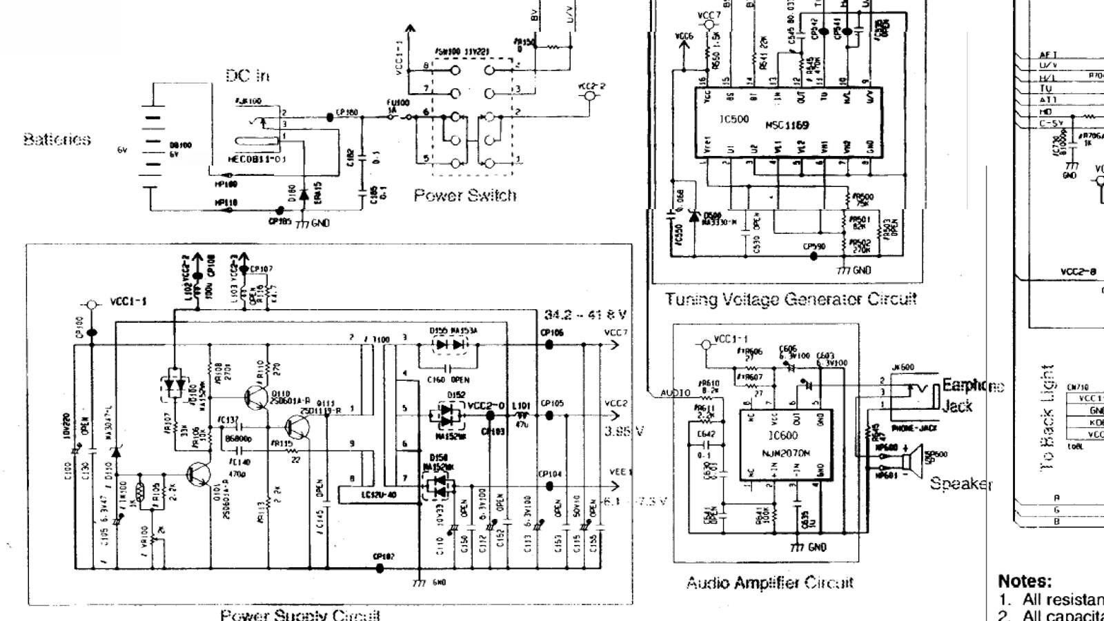
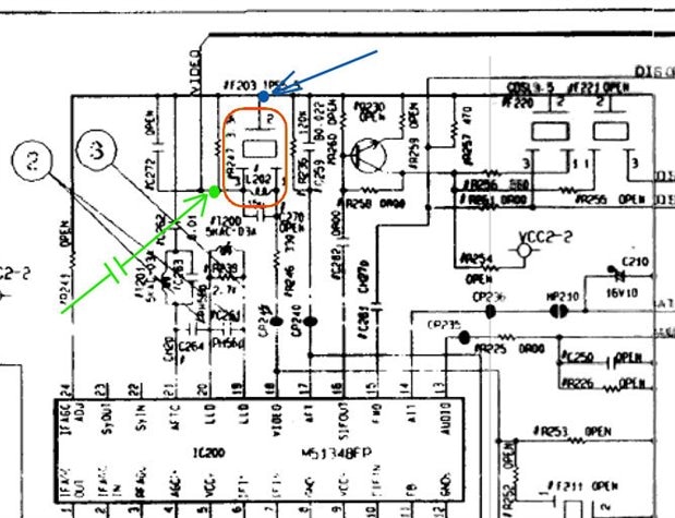
Here are some pictures of what I'm working with, do you think it's possible?


Rov


image

image

image

image

image

  • Sign in to reply
  • Cancel

Top Replies

  • shabaz
    shabaz over 9 years ago +4 suggested
    Hi Rovert, Check out the data sheet (PDF) for the Mitsubishi M51348FP IC on that board, you can see there is a ceramic resonator (probably the one above the two cans in your second photo) and you could…
  • shabaz
    shabaz over 9 years ago in reply to RovertScott +1
    Hi Rovert, I was originally thinking lift the resonator on short wires, remove the wire that is connected to pin 18, and connect your video feed (via a 10nF capacitor) to the pin on the resonator that…
  • clem57
    0 clem57 over 9 years ago

    Looking at http://support.radioshack.com/support_video/doc48/48495.htm it appears it can take a/v in. Why not splice a cable together to adapt RCA to this A/V.

    C

    • Cancel
    • Vote Up 0 Vote Down
    • Sign in to reply
    • Verify Answer
    • Cancel
  • RovertScott
    0 RovertScott over 9 years ago in reply to clem57

    I don't think that applies to this model. From what I can tell, that A/V jack is just for an external antenna.

    I've tried using various connections, but to no avail...

    It works with old game consoles such as the NES and SNES but they use an RF signal tuned to channel 3.

    Based on the traces, it appears it's wired to the same as the standard antenna.

    • Cancel
    • Vote Up 0 Vote Down
    • Sign in to reply
    • Verify Answer
    • Cancel
  • screamingtiger
    0 screamingtiger over 9 years ago in reply to RovertScott

    All you cant do is convert the composite signal to RF.

    UP front cost will be more expensive than just buying a TFT lcd screen designed for the Pi.

    http://www.mcmelectronics.com/product/83-16871?t=2&utm_expid=8634549-27.0czCl7fSQamjILoiAH9mgA.1&utm_referrer=http%3A%2F%2Felectronics.mcmelectronics.com%2Fsearch%3Fcataf%3D%26view%3Dlist%26w%3Dpi%2Bscreen%26x%3D0%26y%3D0


    $34 USD?  I mean unless you just want the work for some reason I would go this route.

    • Cancel
    • Vote Up 0 Vote Down
    • Sign in to reply
    • Verify Answer
    • Cancel
  • shabaz
    0 shabaz over 9 years ago

    Hi Rovert,


    Check out the data sheet (PDF) for the Mitsubishi M51348FP IC on that board, you can see there is a ceramic resonator

    (probably the one above the two cans in your second photo) and you could try to feed the signal into there

    (temporarily break a track or lift that resonator out and extend it on very short wires and use a capacitor (e.g. 10nF) in series with your output from the RPI)

    - try both ends, one should work, and ground is the center of that part.

    Bear in mind you need to enable the composite output on the RPI (it defaults to HDMI) - or use some other composite signal source for now.

    image


    EDIT: Now I look a bit closer, it appears this could have been the areas where additional stuff is needed for the model with A/V input -

    see the photo below, the red circled area is possibly where the video wire was connected, and the pink area is some level adjustment perhaps,

    but is missing in the BoM for this model. Possibly SW200 (the white area on the left with the red marker paint on it) was used to control it.

    In the absence of a circuit diagram it would be hard to know for sure.

    Anyway, the ceramic resonator method mentioned above hopefully could work - it won't harm anything to try.


    image

    • Cancel
    • Vote Up +4 Vote Down
    • Sign in to reply
    • Verify Answer
    • Reject Answer
    • Cancel
  • RovertScott
    0 RovertScott over 9 years ago in reply to shabaz

    I used my multimeter to check the continuity of those pads and it appears that half of them are connected to ground.

    Thanks to the datasheet you found, I know that the M5204FP converts the Composite signal to Component for the LCD.

    The M51343FP, however, converts the RF Signal to Composite.

    If there was a way to input Composite signal, the first step would be breaking the circuit by inserting an A/V Jack.

    Then I'm assuming the chip that controls the channel selector automatically switches to INPUT mode.

    That's the first issue, I need to find a way to get to INPUT mode.

    image


    image

    • Cancel
    • Vote Up 0 Vote Down
    • Sign in to reply
    • Verify Answer
    • Cancel
  • shabaz
    0 shabaz over 9 years ago in reply to RovertScott

    Hi Rovert,


    I think you mean M51348FP, not M51343FP, right? (the text is hard to read on the IC in the photo).

    The pin 18 goes to one end of that ceramic resonator I mentioned, according to the schematic, so you could lift a pin there (in practice you'll need to lift out the entire resonator and place it on very small wires) and you'll be able to feed your video signal in there (i.e. isolate pin 18) so that it no longer goes into the ceramic resonator.

    It might not work (depends on levels) but it is worth a try - may be easier than trying to decipher how the A/V input functioned on the other models, because it appears some of those components are missing on the board.

    • Cancel
    • Vote Up 0 Vote Down
    • Sign in to reply
    • Verify Answer
    • Cancel
  • RovertScott
    0 RovertScott over 9 years ago in reply to shabaz

    I went back and tested the pins for continuity.

    So, you're suggesting I remove the resonator and solder a wire to the blue solder point?

    I'm also currently trying to follow the "Blue Line" and mark out where it's going.


    Sorry if I'm being too cautious, I want to learn what is going on while preventing myself from making mistakes that might fry something.


    image

    EDIT: I HAVE FOUND THE SERVICE MANUAL!


    image

    image

    image

    image

    image

    • Cancel
    • Vote Up 0 Vote Down
    • Sign in to reply
    • Verify Answer
    • Cancel
  • shabaz
    0 shabaz over 9 years ago in reply to RovertScott

    Hi Rovert,


    I was originally thinking lift the resonator on short wires, remove the wire that is connected to pin 18, and connect your video feed (via a 10nF capacitor)  to the pin on the resonator that was connected to pin 18.

    However, it is unnecessary, and easier still, just entirely remove the resonator, and connect your video feed (via a 10nF capacitor) to the pin on the resonator that was not connected to pin 18.

    And ground will be the center hole where the resonator was.

    You can't destroy anything by probing around in that area, as long as you have your 10nF capacitor in series.


    Once you have lifted out that resonator, the screen will likely entirely dim (i.e. no more snow, since the demodulator and entire RF section has been removed by your action of removing that part).

    Then when you have a composite video feed on the pin that was not connected to pin 18, you should see something - hopefully.


    EDIT: Just saw the schematics, you will also have to remove L202 which is that green part right next to the resonator.

    EDIT 2: On second thoughts, leave L202 there and try it first. If it doesn't work, remove L202. No risk of damage occurring in either case.


    Just to make it clearer, this is your goal; you want to remove the bits in red (resonator and inductor L202), because this will isolate pin 18 of the integrated circuit.

    Then you want to feed your video to the point marked in green (via a capacitor), with your ground connection being the point marked in blue.


    image

    • Cancel
    • Vote Up +1 Vote Down
    • Sign in to reply
    • Verify Answer
    • Cancel
element14 Community

element14 is the first online community specifically for engineers. Connect with your peers and get expert answers to your questions.

  • Members
  • Learn
  • Technologies
  • Challenges & Projects
  • Products
  • Store
  • About Us
  • Feedback & Support
  • FAQs
  • Terms of Use
  • Privacy Policy
  • Legal and Copyright Notices
  • Sitemap
  • Cookies

An Avnet Company © 2025 Premier Farnell Limited. All Rights Reserved.

Premier Farnell Ltd, registered in England and Wales (no 00876412), registered office: Farnell House, Forge Lane, Leeds LS12 2NE.

ICP 备案号 10220084.

Follow element14

  • X
  • Facebook
  • linkedin
  • YouTube