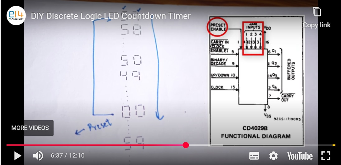
Hey everyone, I'm trying to create a countdown system, but I'm having trouble understanding how everything works together. I'm not really sure how to chain the parts properly. Could someone please show me a clear schematic or example of how to connect everything step by step?

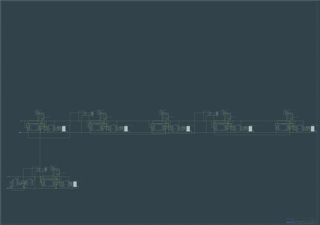
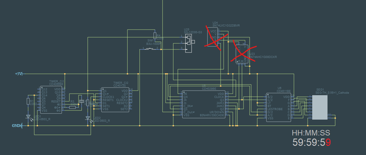
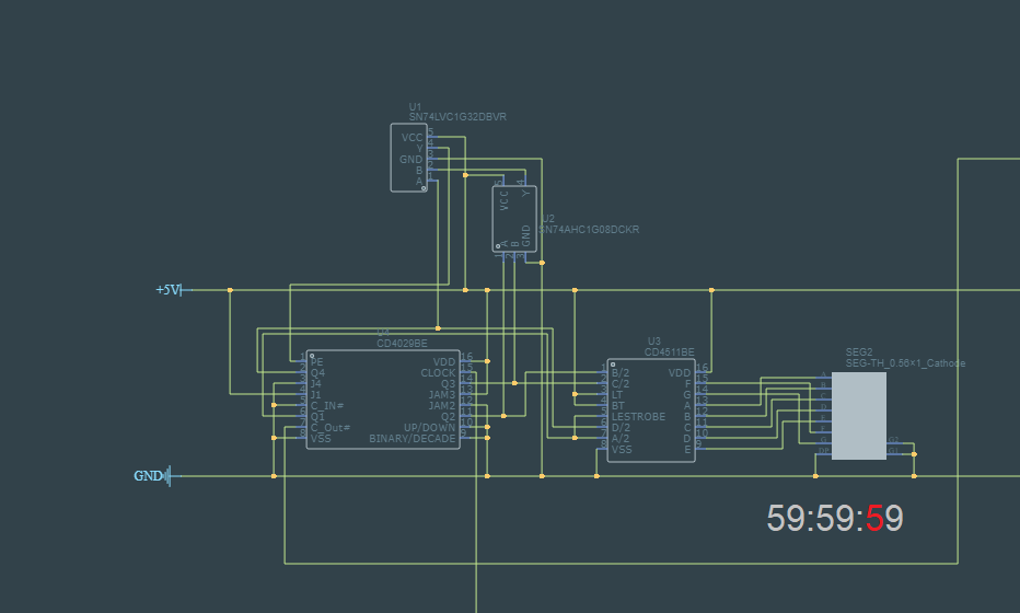
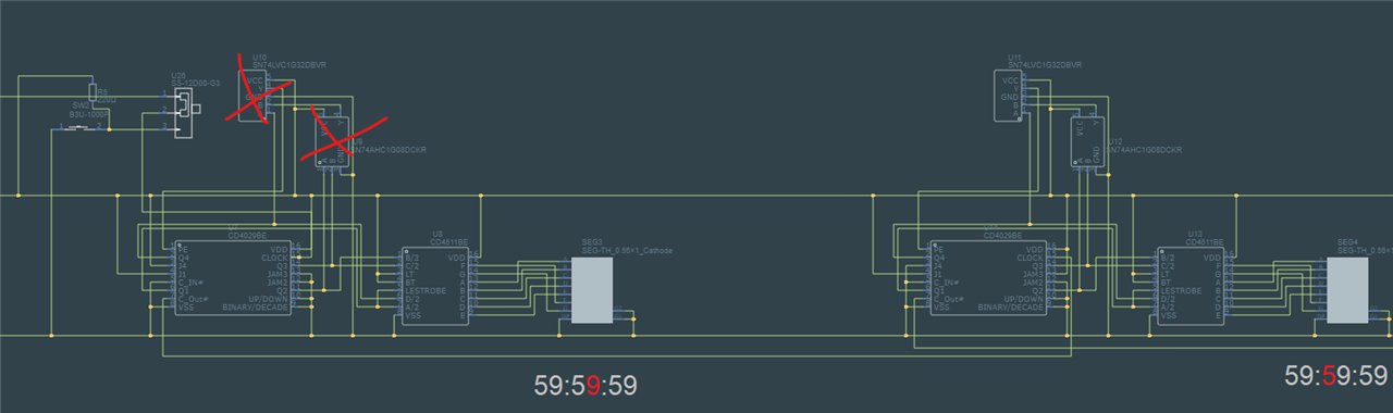
 like this?
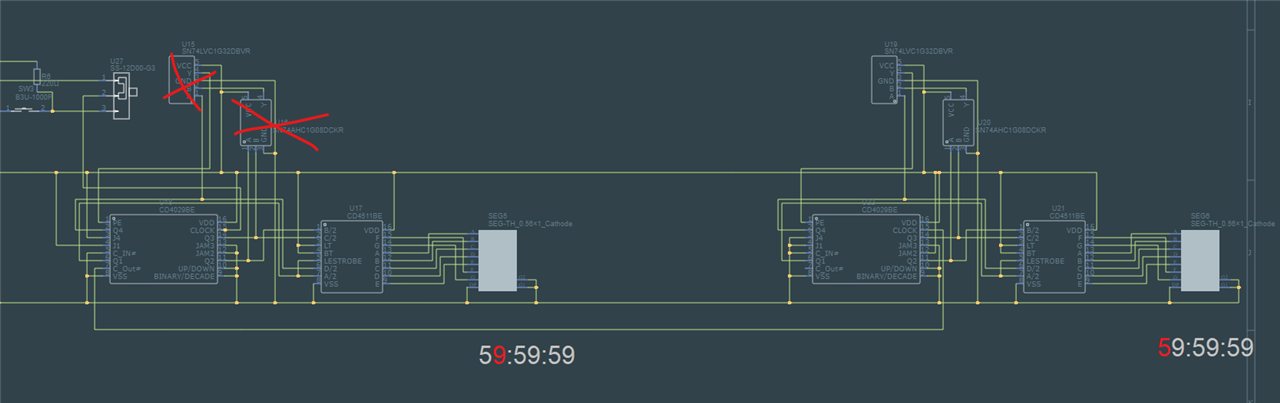