element14 Community
element14 Community
    Register Log In
  • Site
  • Search
  • Log In Register
  • About Us
  • Community Hub
    Community Hub
    • What's New on element14
    • Feedback and Support
    • Benefits of Membership
    • Personal Blogs
    • Members Area
    • Achievement Levels
  • Learn
    Learn
    • Ask an Expert
    • eBooks
    • element14 presents
    • Learning Center
    • Tech Spotlight
    • STEM Academy
    • Webinars, Training and Events
    • Learning Groups
  • Technologies
    Technologies
    • 3D Printing
    • FPGA
    • Industrial Automation
    • Internet of Things
    • Power & Energy
    • Sensors
    • Technology Groups
  • Challenges & Projects
    Challenges & Projects
    • Design Challenges
    • element14 presents Projects
    • Project14
    • Arduino Projects
    • Raspberry Pi Projects
    • Project Groups
  • Products
    Products
    • Arduino
    • Avnet Boards Community
    • Dev Tools
    • Manufacturers
    • Multicomp Pro
    • Product Groups
    • Raspberry Pi
    • RoadTests & Reviews
  • Store
    Store
    • Visit Your Store
    • Choose another store...
      • Europe
      •  Austria (German)
      •  Belgium (Dutch, French)
      •  Bulgaria (Bulgarian)
      •  Czech Republic (Czech)
      •  Denmark (Danish)
      •  Estonia (Estonian)
      •  Finland (Finnish)
      •  France (French)
      •  Germany (German)
      •  Hungary (Hungarian)
      •  Ireland
      •  Israel
      •  Italy (Italian)
      •  Latvia (Latvian)
      •  
      •  Lithuania (Lithuanian)
      •  Netherlands (Dutch)
      •  Norway (Norwegian)
      •  Poland (Polish)
      •  Portugal (Portuguese)
      •  Romania (Romanian)
      •  Russia (Russian)
      •  Slovakia (Slovak)
      •  Slovenia (Slovenian)
      •  Spain (Spanish)
      •  Sweden (Swedish)
      •  Switzerland(German, French)
      •  Turkey (Turkish)
      •  United Kingdom
      • Asia Pacific
      •  Australia
      •  China
      •  Hong Kong
      •  India
      •  Korea (Korean)
      •  Malaysia
      •  New Zealand
      •  Philippines
      •  Singapore
      •  Taiwan
      •  Thailand (Thai)
      • Americas
      •  Brazil (Portuguese)
      •  Canada
      •  Mexico (Spanish)
      •  United States
      Can't find the country/region you're looking for? Visit our export site or find a local distributor.
  • Translate
  • Profile
  • Settings
Project Videos
  • Challenges & Projects
  • element14 presents
  • Project Videos
  • More
  • Cancel
Project Videos
Documents Mega IIe: First Fully Functional Computer built around the Apple Mega-II Chip -- Episode-630
  • Documents
  • Members
  • Mentions
  • Sub-Groups
  • Tags
  • More
  • Cancel
  • New
Join Project Videos to participate - click to join for free!
Related
Recommended
Engagement
  • Author Author: tariq.ahmad
  • Date Created: 22 Nov 2023 6:00 PM Date Created
  • Last Updated Last Updated: 29 Nov 2023 8:58 PM
  • Views 7105 views
  • Likes 11 likes
  • Comments 21 comments

Mega IIe: First Fully Functional Computer built around the Apple Mega-II Chip -- Episode-630

Five years ago, James asked: "Can the Mega-II operate as a computer?" With countless hours of debugging, the help of many fantastic people, and every obscure information resource he could find, James has the answer.  

Jump to: Downloads and Links | Discussion

Watch the Video:

You don't have permission to edit metadata of this video.
Edit media
x
image
Upload Preview
image

This video follows up with another element14 Presents project video. Previously, James took the Mega-II chip out of an Apple IIGS and successfully booted it with custom PCBs. In the project's next phase, he aimed to determine the Mega-II's full functionality. 

image

As a quick review, the Mega-II is an application-specific integrated circuit (ASIC) Apple designed in the late 1980s. It reduced the extremely popular Apple IIe's 5 custom chipset to a single chip. At least, that is what many people have said. Regardless, the Apple IIe featured some of Apple's first custom chips when it reduced the Apple II+ down from about 80 off-the-shelf 7400-series logic chips. 

 image

In his last project video, James got the Mega-II to a point where it would boot to an Applesoft prompt . (the BASIC interpreter built into the IIe's ROM.). However, he could not type anything, so the "computer" wasn't much use. Debugging it was a nightmare due to the massive amount of wiring involved. He decided to take another approach. 

Rev 2 

Stepping back and thinking about the project, James realized he needed more flexibility in testing each Apple II circuit block. Instead of making a large monolithic circuit board, he designed rev2 around a backplane. This modular approach had two significant benefits. First, it lowered the cost of spinning new circuit boards. And second, eliminating the colossal wire mess made debugging significantly easier. 

image

James says his favorite aspect of this design was how the Digilent Digital Discovery connected directly to the backplane! With deep capture memory, these high-speed logic analyzers can simultaneously sample up to 40 signals: 24 at high speed and 16 at a lower rate. They are part of the Discovery series of tools from Digilent. You might remember from the first part that James had written a decoder for the Waveforms software to help decode Apple II memory accesses from Digilent. (In the first part, James wrote a decoder for the Waveforms software to help decode Apple II memory accesses.) 

Keyboard 

 image

One objective James had for this project was to use a USB keyboard. Why do so many retro projects use PS/2 anyway? Since the RP2040 found on the Pi Pico could support being a USB Host AND has programmable IO pins, it is a perfect option for the keyboard interface. 

image 

The programmable IO is critical because the Mega-II's data bus must be driven within 150 nanoseconds of a specific memory operation. The RP2040's PIO can respond fast enough. It took all 32 instructions of one PIO state machine to implement the logic necessary to respond to those Apple II I/O calls. 

Slotmaker 

The secret to getting the keyboard to work was another ASIC in the IIGS called Slotmaker. Oddly, Apple's engineers put one of the KSEL (keyboard control) lines on this chip for some reason. That said, Slotmaker's primary function is managing slots in the IIGS.  

image 

Slotmaker's primary function is selecting between the slots or internal devices in an IIGS. For example, the disk controller is in virtual slot 6. Slotmaker allows the user to use the internal device or change to the slot. 

Another objective of the Mega IIe project was to incorporate disk control into the final board. Therefore, the Slotmaker chip was required for two reasons: the KSEL0 keyboard signal and to talk to the disk controller chip.  

Disk Drives 

image 

In 1978, Steve Wozniak took a completely different approach to disk drive control from other personal computer vendors. He created a hardware-reduced controller that implemented a software-controlled state machine. The result was the Disk ][ Controller Card. 

Later in the 1980s, Wendall Sanders took that design and created a custom ASIC called the Integrated Woz Machine or IWM.  

image 

James incorporated the IWM into the Mega-II design but encountered a problem when looking for the "boot code." It turns out he had to patch his ROM to include it! 

Video 

Now that saving and loading programs was possible, James wanted to improve the video signal.  

One of the unique features of the Mega-II chip is how it outputs video information. There is a signal called SERVID. This signal provides a line of luma and chroma information.  

image 

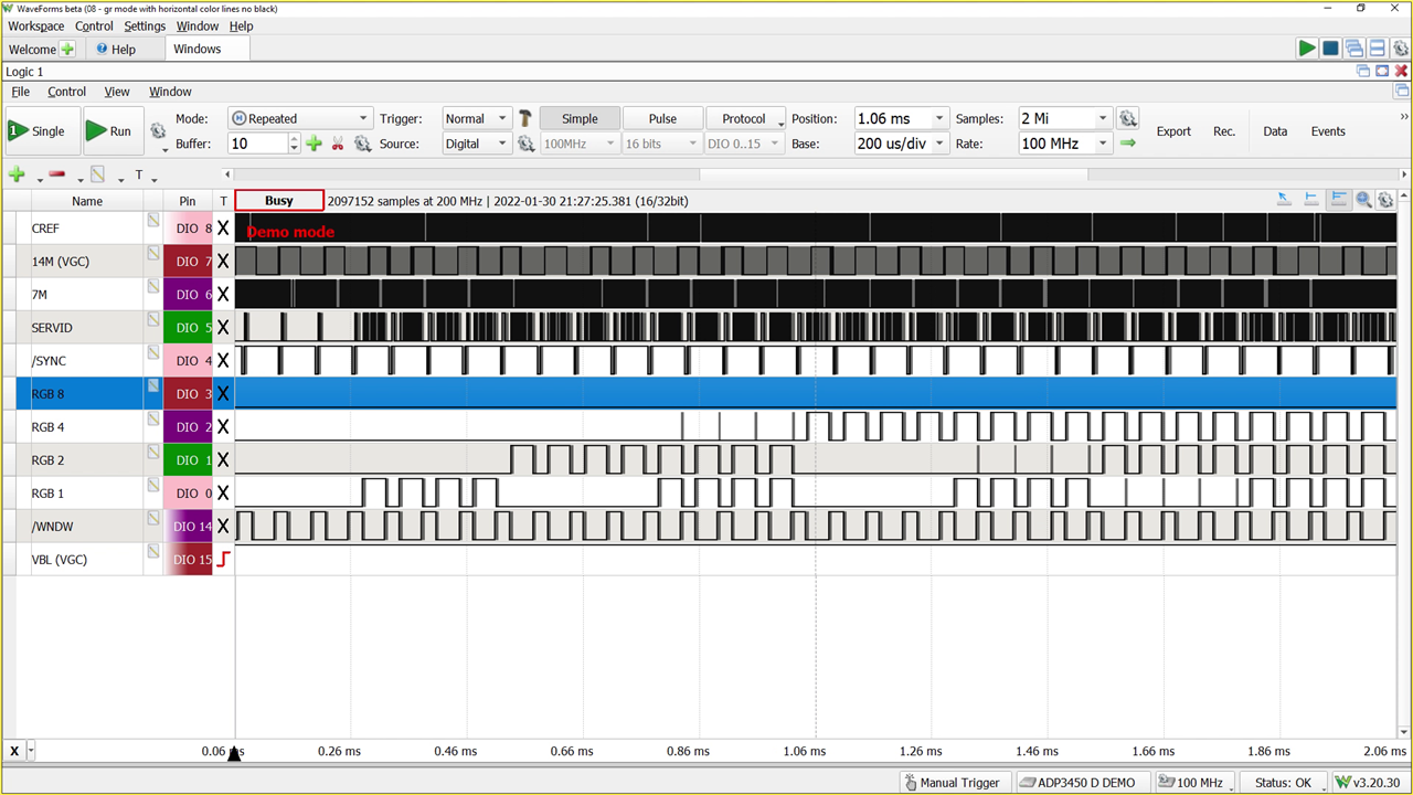
On Mega-II, the signals RGB8, RGB4, RGB2, and RGB1 contain the same data as SERVID but in a de-multiplexed format. James decided to use another RP2040 to capture those signals (at 14 MHz) to capture each "pixel" of color information.  

James focused his efforts on the input side with another PIO program to capture the RGBx data and used a library called PicoVGA to handle the output side. The result was super clean output and the end of the project's second phase. 

Rev 3 

The project's third phase is the final goal: a single PCB incorporating all of Rev 2's features. The design task was arduous, but James worked through all the necessary issues to make the chips and connectors fit. 

 image

And, of course, he added some blinky LEDs, because LEDs make every project better. 

James encountered vastly different experiences between Rev 2 and Rev 3. With Rev 2, James ran into a few problems, but they were all relatively easy to solve or occurred because of misconceptions about Mega II. With Rev 3, however, the issue list was completely different. You won't believe how much trouble he ran into! 

Enclosure 

To honor this design, James modified a model of the Apple IIe he found on Grabcad. That model only contained faces, so it was not 3D printable as-is. After creating a printable model, James got to sanding, painting, and gluing, as well as adding mounting holes, and making an appropriate back panel. 

image 

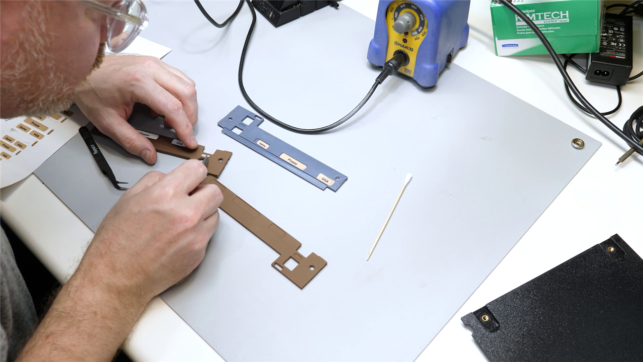
With the help of some custom decals, the result is an adorably sized Apple IIe computer. On the front, it has a USB Keyboard and Earphone Jack. The back has Power, VGA, Floppy Drive, and Gameport (Joystick) ports.  

The Future 

In the future, James hopes to do a few more things with the Mega IIe. First, he is still trying to get Smartport support to work. This feature would enable hard drive support through the IWM. Of course, he wants to correct some mistakes made on the Rev 3 logic board. Finally, he'd like to re-design the enclosure to be multiple pieces. But what do you think about the design, and what would you add if you built a computer based on the Mega-II chip? 

 image

Download and Links: 

  •  World’s First Single-Chip Apple II Boots! -- Episode 532 
  •  Emulate an EPROM - How Hard Could it Be? -- Episode 517 
  • Mega IIe Design Files (Github): https://github.com/baldengineer/mega-iie
  • Apple IIGS Schematic in Bit Preserve: https://github.com/baldengineer/bit-preserve/tree/main/Apple/Apple%20IIGS/IIgs  
  • Jon Relay's Apple II I/O Memory (Soft Switches) 
  • David Schmidt's Tiger Learning Computer documentation project https://github.com/david-schmidt/tlc-apple2
  • PicoVGA Library https://github.com/Panda381/PicoVGA
  • ProDOS 8 (Active Development)
  • Identify ][ (Apple II Diagnostic Program)
  • DOLRES Library and Demos (Spinning Apple Logo)
  • Apple Iie Grabcad Model (faces only!)

Bill of Material:

Product Name Quantity Buy Kit
RP2040, 32-bit dual-core Arm Cortex-M0+ 1 Buy Now
Pi Pico (RP2040) 1 Buy Now
Digital Discovery 1 Buy Now
74HC245, octal buffer 1 Buy Now
74HC573, transparent latch 1 Buy Now
Surface Mount Dip Switches (8 position) 1 Buy Now
Grey PLA 1 Buy Now
 

Additional Parts:

Mega-II, Slotmaker, and IWM ASIC from Apple IIGS
Patience, a metric ton of it

element14 presents

element14 presents  |  About James |  Project Videos

  • Apple II Hardware Resurrection
  • vintage computer restoration
  • Mega IIe Project Showcases
  • Electronics DIY Storytelling
  • PicoVGA Video Output Innovations
  • e14p_JBE
  • Mega II Chip Exploration
  • Modular Hardware Development
  • RP2040 Integration Techniques
  • Community-Engaged Electronics Exploration
  • Apple IIe IIGS Computer Mega-II Chip
  • Apple IIe Custom Enclosure
  • Technical Challenges in Retro Computing
  • Electronics Enthusiast Blogs
  • USB Keyboard Retro Integration
  • Community-driven Retro-Tech
  • Retro Computing Projects
  • friday_release
  • Share
  • History
  • More
  • Cancel
Actions
  • Share
  • More
  • Cancel
  • Sign in to reply

Top Comments

  • baldengineer
    baldengineer over 1 year ago +4
    It's been a heck of a ride. Even though the project is done, I have many more ideas because of it. Thanks again to everyone who supported the idea and helped me figure stuff out. Who knew reverse engineering…
  • baldengineer
    baldengineer over 1 year ago in reply to tpfaff100

    I sent you a "friend" request so we can direct message. The last board I have left has a couple of sockets/headers on it. Originally, I was going to try using this to program the EEPROMs via fly wires. However, I realized mid-way through the soldering that the Mega-II pins lacked access to the write and enable signals. (And then later realized they weren't usable anyway!)

    image

    If you're okay with that, then I'll be happy to send it to you.

    This is one of the "working" boards (before all of the bodging.)

    • Cancel
    • Vote Up 0 Vote Down
    • Sign in to reply
    • More
    • Cancel
  • tpfaff100
    tpfaff100 over 1 year ago in reply to baldengineer

    Thank you!  T

    • Cancel
    • Vote Up 0 Vote Down
    • Sign in to reply
    • More
    • Cancel
  • baldengineer
    baldengineer over 1 year ago in reply to tpfaff100

    I might have one more left. I can check mid next week. 

    • Cancel
    • Vote Up -1 Vote Down
    • Sign in to reply
    • More
    • Cancel
  • baldengineer
    baldengineer over 1 year ago in reply to tpfaff100

    I did not post the gerbers, so you would need to generate them from the KiCad files. "Rev3" is the board I used in the video/build. Rev 3B has all of the (known) issues fixed. But I haven't tested the board to see if I introduced any new ones. Slight smile

    Also, I assume by "etch" you mean sending to a PCB fab. The tolerances on the traces are far too small for DIY etching. 

    • Cancel
    • Vote Up 0 Vote Down
    • Sign in to reply
    • More
    • Cancel
  • tpfaff100
    tpfaff100 over 1 year ago in reply to baldengineer

    Which file in the repo the one with the four-level board to be etched?  https://github.com/baldengineer/Mega-IIe/blob/main/kicad%20files/gd%20rev3b/gd%20rev3b.kicad_pro ?

    • Cancel
    • Vote Up 0 Vote Down
    • Sign in to reply
    • More
    • Cancel
  • tpfaff100
    tpfaff100 over 1 year ago

    Hi.  If you have a board for sale I'd like to have one.  I don't want a functional 'mega-iie' just like to have a copy of your motherboard.  Did you have a few extra of those working boards that requires the jumpers?  If not a working board, then maybe one of the bad bad boards with the bad layer?  Just tho't I'd ask... would be fun to have one just for the novelty.  I do moderate hardware work, mostly with old analog hardware like the Burr Brown 4423- don't do much digital stuff... I just don't have the patience (or eyes anymore) for digital work!  Cheers and hey- nice project.  Thomas

    • Cancel
    • Vote Up 0 Vote Down
    • Sign in to reply
    • More
    • Cancel
  • baldengineer
    baldengineer over 1 year ago in reply to Aaron0

    You can download them here:

    https://github.com/baldengineer/mega-iie

    They're in the enclosure directory.

    • Cancel
    • Vote Up 0 Vote Down
    • Sign in to reply
    • More
    • Cancel
  • Aaron0
    Aaron0 over 1 year ago

    Hi, will you upload the 3d print files for the case or can we buy them from you?

    • Cancel
    • Vote Up 0 Vote Down
    • Sign in to reply
    • More
    • Cancel
  • kellyhensen
    kellyhensen over 1 year ago

    Anybody else want a reset button?  RE: RESET! for the Apple ][. (pronounced "reset dammit") 

    • Cancel
    • Vote Up 0 Vote Down
    • Sign in to reply
    • More
    • Cancel
  • kmikemoo
    kmikemoo over 1 year ago

    Absolutely incredible!  Just... WOW!

    • Cancel
    • Vote Up 0 Vote Down
    • Sign in to reply
    • More
    • Cancel
>
element14 Community

element14 is the first online community specifically for engineers. Connect with your peers and get expert answers to your questions.

  • Members
  • Learn
  • Technologies
  • Challenges & Projects
  • Products
  • Store
  • About Us
  • Feedback & Support
  • FAQs
  • Terms of Use
  • Privacy Policy
  • Legal and Copyright Notices
  • Sitemap
  • Cookies

An Avnet Company © 2025 Premier Farnell Limited. All Rights Reserved.

Premier Farnell Ltd, registered in England and Wales (no 00876412), registered office: Farnell House, Forge Lane, Leeds LS12 2NE.

ICP 备案号 10220084.

Follow element14

  • X
  • Facebook
  • linkedin
  • YouTube