element14 Community
element14 Community
    Register Log In
  • Site
  • Search
  • Log In Register
  • About Us
  • Community Hub
    Community Hub
    • What's New on element14
    • Feedback and Support
    • Benefits of Membership
    • Personal Blogs
    • Members Area
    • Achievement Levels
  • Learn
    Learn
    • Ask an Expert
    • eBooks
    • element14 presents
    • Learning Center
    • Tech Spotlight
    • STEM Academy
    • Webinars, Training and Events
    • Learning Groups
  • Technologies
    Technologies
    • 3D Printing
    • FPGA
    • Industrial Automation
    • Internet of Things
    • Power & Energy
    • Sensors
    • Technology Groups
  • Challenges & Projects
    Challenges & Projects
    • Design Challenges
    • element14 presents Projects
    • Project14
    • Arduino Projects
    • Raspberry Pi Projects
    • Project Groups
  • Products
    Products
    • Arduino
    • Avnet Boards Community
    • Dev Tools
    • Manufacturers
    • Multicomp Pro
    • Product Groups
    • Raspberry Pi
    • RoadTests & Reviews
  • Store
    Store
    • Visit Your Store
    • Choose another store...
      • Europe
      •  Austria (German)
      •  Belgium (Dutch, French)
      •  Bulgaria (Bulgarian)
      •  Czech Republic (Czech)
      •  Denmark (Danish)
      •  Estonia (Estonian)
      •  Finland (Finnish)
      •  France (French)
      •  Germany (German)
      •  Hungary (Hungarian)
      •  Ireland
      •  Israel
      •  Italy (Italian)
      •  Latvia (Latvian)
      •  
      •  Lithuania (Lithuanian)
      •  Netherlands (Dutch)
      •  Norway (Norwegian)
      •  Poland (Polish)
      •  Portugal (Portuguese)
      •  Romania (Romanian)
      •  Russia (Russian)
      •  Slovakia (Slovak)
      •  Slovenia (Slovenian)
      •  Spain (Spanish)
      •  Sweden (Swedish)
      •  Switzerland(German, French)
      •  Turkey (Turkish)
      •  United Kingdom
      • Asia Pacific
      •  Australia
      •  China
      •  Hong Kong
      •  India
      •  Korea (Korean)
      •  Malaysia
      •  New Zealand
      •  Philippines
      •  Singapore
      •  Taiwan
      •  Thailand (Thai)
      • Americas
      •  Brazil (Portuguese)
      •  Canada
      •  Mexico (Spanish)
      •  United States
      Can't find the country/region you're looking for? Visit our export site or find a local distributor.
  • Translate
  • Profile
  • Settings
Project Videos
  • Challenges & Projects
  • element14 presents
  • Project Videos
  • More
  • Cancel
Project Videos
Documents Practical DIY Pi Pico Current Load Circuits -- Episode-645
  • Documents
  • Members
  • Mentions
  • Sub-Groups
  • Tags
  • More
  • Cancel
  • New
Join Project Videos to participate - click to join for free!
Related
Recommended
Engagement
  • Author Author: tariq.ahmad
  • Date Created: 7 Mar 2024 7:35 PM Date Created
  • Last Updated Last Updated: 7 Mar 2024 7:57 PM
  • Views 3461 views
  • Likes 10 likes
  • Comments 8 comments

Practical DIY Pi Pico Current Load Circuits -- Episode-645

For the electronics projects you’re working on, one thing is for sure: you need to power it! Anything from directly connected to the outlet, a battery, a buck converter to a linear regulator and so on. When consider testing a power supply, the first thing you should think about is how to measure its output voltage. Another important aspect that should be tested is how that power supply performs under load. In this video, Milos will show us a few different practical circuits to achieve this. 

Watch the Video:

You don't have permission to edit metadata of this video.
Edit media
x
image
Upload Preview
image

Downloads & Links | Bill of Material | Discussion

Let’s go through the different circuits that Milos develops and demonstrates in the video: 

The Analog Circuit Version 

An easy circuit to test your power supply involves only five components. The added benefit is that it can be made cheaply with just fifteen minutes of soldering!  

image

This is a simple circuit that gives great results. The Op-Amp in the middle regulates the gate of the N channel MOSFET so that a constant current is flowing through it. This is achieved by having the feedback voltage come from the power resistor which is used as a shunt here for measuring current. The Op-Amp is trying to keep the voltage U1 and U2 equal, and we’re controlling the voltage U1 by setting it with the potentiometer, and that is how we are setting our desired current for this circuit. For any kind of quick test, this circuit is great, if you want to make it handle even higher currents, you can put a couple of MOSFETs in parallel and attach them to a heatsink.

A Digital Circuit Version 

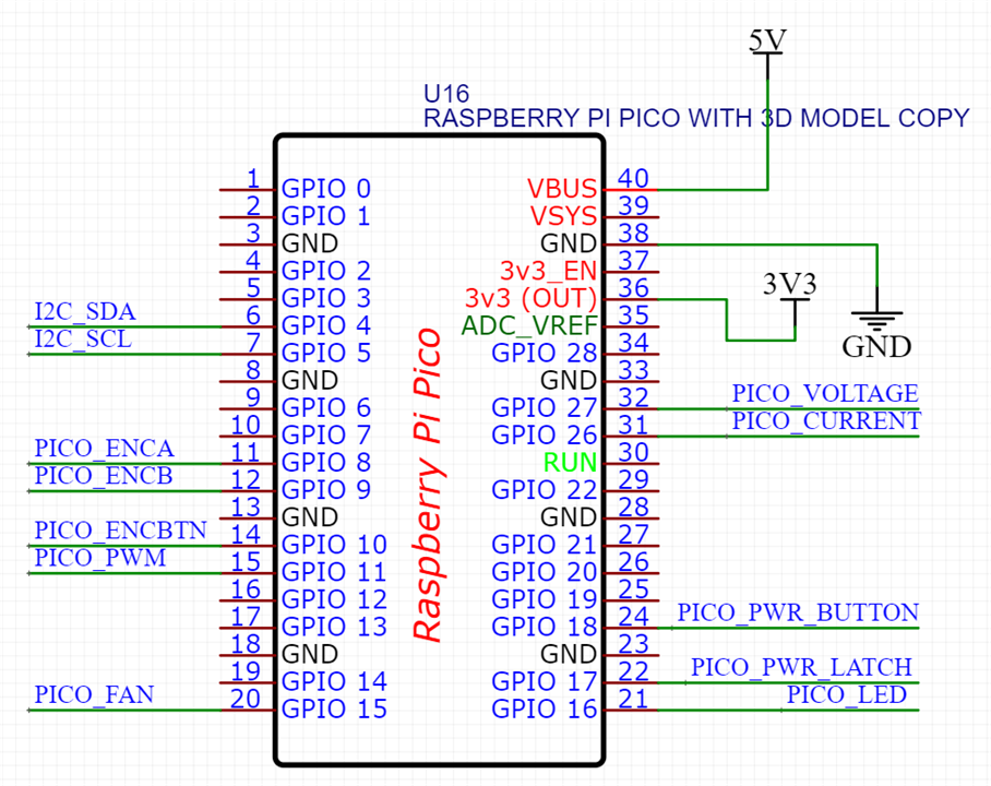
There are numerous ways of being able to digitize this, in the video, Milos decides to go with an approach that works in a similar fashion to the analog circuit, but the reference that is being sent to the Op-Amp is done through a microcontroller, or more specifically, a Raspberry Pico W. 

image

The feedback now comes from an ACS current sensor and is directly fed to the Op-Amp. Milos originally wanted to use an INA219 module which is an I2C current and voltage sensor, but it died during testing. One thing he warns about is that you should be careful when buying clone boards with the ACS sensors since a lot of times they can go unstable as he experienced. 

The ACS current sensor returns and analog voltage 0-5V with 2.5V being 0mA voltage since the sensor is bidirectional. To feed the reference to the regulator Op-Amp, we see that Milos adds a summing amplifier which adds a 2.5V signal coming from a potentiometer and the signal from the Raspberry Pico so that the reference can be set between 2.5V and 5V. 

This digital version enables the user to control the current by varying the PWM duty cycle through software, additional things can be done with this setup as well, like constant power draw and battery capacity measurement. 

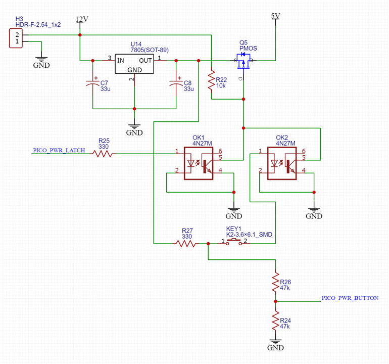
The Simple Button ON/OFF Circuit 

The last part of electronics that he wanted to do was the powering up of the whole system. The easiest way to accomplish that would be by using a switch, but Milos opted to go with a button, which needs some extra circuitry. To get some help on this topic, Milos leaned on the knowledge of the members of the Community, receiving a great deal of fantastic responses and suggestions, ultimately going with the idea that was most recommended and the benefits it brought. You can check all the ideas that are discussed here: 

  •  Press ON - Hold OFF Latching Circuit  

The Final Circuit 

image

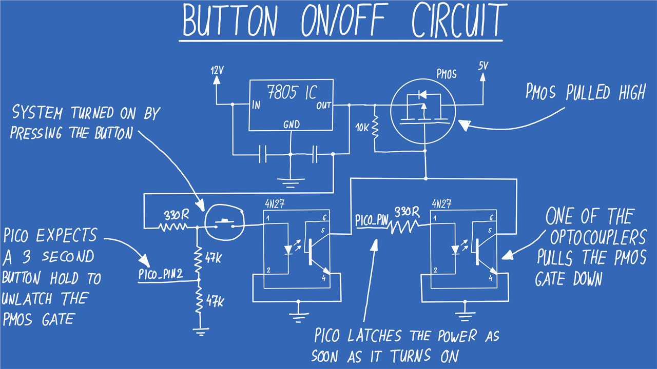
This circuit works by using high side switching with a P channel MOSFET, that’s done through 2 optocouplers, one is controlled by a button, and the other one is controlled by the Raspberry Pico. The idea is that Pico drives the pin high as soon as it turns ON, latching the power ON. To turn OFF the device, the Pico has a pin that can detect whether the button has been pressed or not, if it detects that the button has been pressed for longer than 3 seconds, it unlatches the power and the whole device turns OFF once the button is released. 

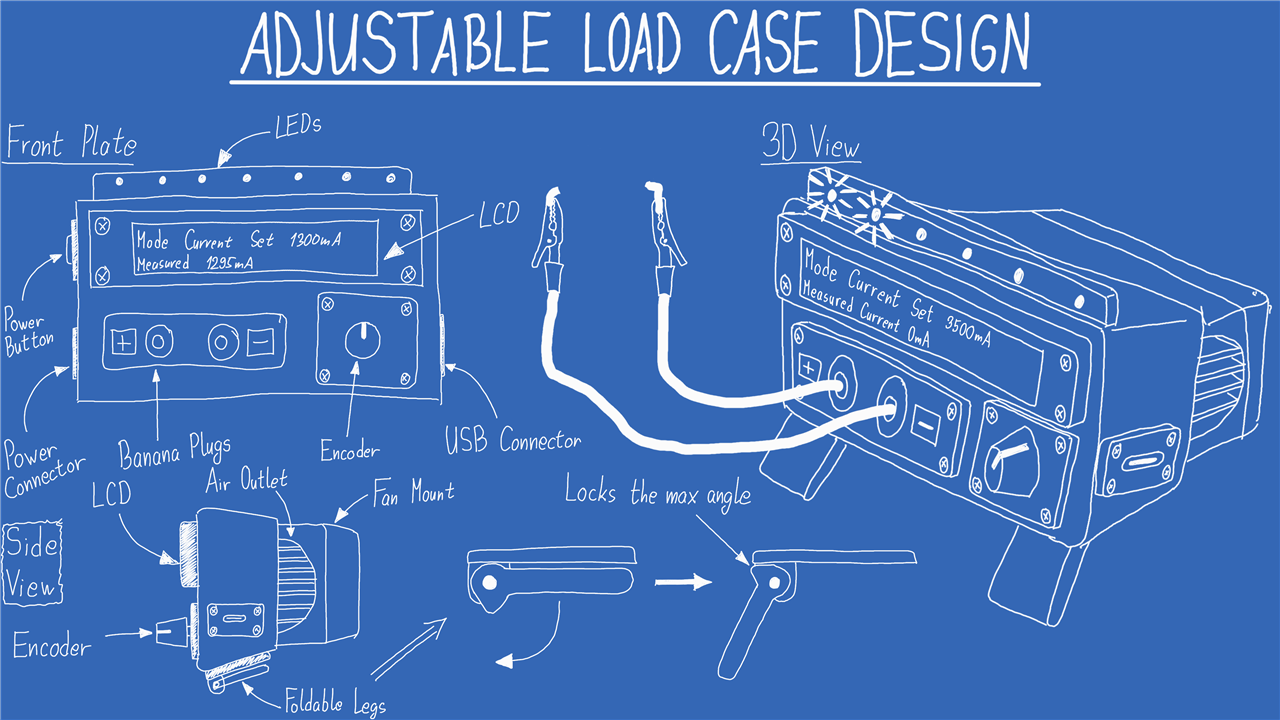
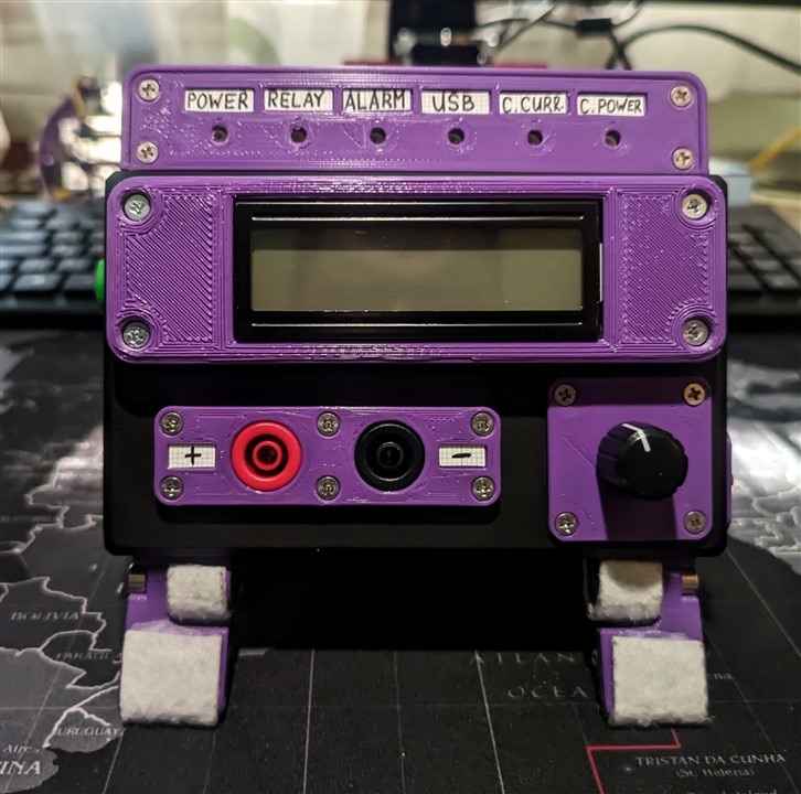
The Enclosure Design

The only thing left to do was for Milos to design an enclosure. Deciding to start with an off-the-shelf enclosure and add 3D printed parts to it. Milos wanted a 16x2 LCD in the front for displaying information, LEDs for signals and 4mm banana jacks for connecting what’s being tested. This steered the eventual design. You can see the full design as well as the finished device below. 

image

{gallery}My Gallery Title

image

image

image

Appendix: Schematics 

{gallery}My Gallery Title

image

image

image

image

Downloads & Links

  • Download Code & CAD Files!
  •  Press ON - Hold OFF Latching Circuit  

Bill of Material:

Product Name Quantity Buy Kit
MULTICOMP PRO Banana Test Connector, Jack, Panel Mount, 32 A, 1 kV, Nickel Plated Contacts, Black 1 Buy Now
MULTICOMP PRO Banana Test Connector, Jack, Panel Mount, 32 A, 1 kV, Nickel Plated Contacts, Red 1 Buy Now
DFROBOT Wattmeter, Gravity: I2C Digital, Arduino UNO/Raspberry Pi 3B Boards 1 Buy Now
DFROBOT Expansion Board, Gravity I2C 16x2 Arduino LCD, DFRduino UNO R3 Board 1 Buy Now
INFINEON Power MOSFET, N Channel, 100 V, 36 A, 0.044 ohm, TO-220AB, Through Hole 4 Buy Now
SEEED STUDIO LED Strip, Waterproof, WS2813 RGB, 60 LED/m, 1m, 5V, Seeedunio, Arduino+BaseShild Board 1 Buy Now
DFROBOT Rotary Encoder Module, Breakout, Fermion, EC11, DFRduino UNO R3 Board 1 Buy Now
MULTICOMP 3D Printer Filament, 1.75mm Dia, Purple, PLA, 1 kg 1 Buy Now
CAMDENBOSS Plastic Enclosure, Multipurpose, ABS, 45 mm, 80 mm, 130 mm, IP40 1 Buy Now
ABL HEATSINKS Heat Sink, TO-220/218, 3.7 °C/W, TO-218, TO-220, 50 mm, 28 mm, 75 mm 1 Buy Now
RASPBERRY-PI SBC, Raspberry Pi Pico W, RP2040, ARM Cortex-M0+, 264kB RAM, 2MB Flash, Wifi, Micro-USB 1 Buy Now
TEXAS INSTRUMENTS LM324AN/NOPB 1 Buy Now
VISHAY 4N27 2 Buy Now
INFINEON IRF9530NPBF 1 Buy Now
STMICROELECTRONICS L78M05ABV 1 Buy Now
Fan 60mm 12V - MULTICOMP MC011527 1 Buy Now
 

Additional Parts:

Passive components and wires - Parts like resistors, capacitors, wires, perfboard, etc
Screws - M2.5 and M3 screws
Push button - Any kind of button
Barrel jack connector and 12V charger - Connector used to power the whole device as well a suitable charger that's at 12V

element14 presents

element14 presents  |  About Milos Rasic |  Project Videos

  • Electronic components analysis
  • mosfet
  • battery capacity tester
  • Electronics testing
  • dfrobot
  • lcd
  • test equipment
  • Power Latch Circuit
  • Raspberry Pico W
  • op-amp
  • Adjustable Load
  • constant current
  • e14p_Milos
  • Power supply evaluation
  • 3D Printing
  • diy
  • Milos electronics videos
  • operational amplifier
  • raspberry pi
  • Circuit development insights
  • Precision testing
  • Real-world testing scenarios
  • Maker tutorials
  • constant current load
  • Digital circuitry
  • Electronics innovation
  • Raspberry Pico microcontroller
  • friday_release
  • Current sensor challenges
  • Analog circuits
  • 3D-printed enclosure
  • current load
  • Technical details in testing
  • diy test equipment
  • DIY Battery Capacity Tester
  • Share
  • History
  • More
  • Cancel
Actions
  • Share
  • More
  • Cancel
  • Sign in to reply
  • dhi67540
    dhi67540 over 1 year ago

    The LCD panel STL(s) are missing from the download

    • Cancel
    • Vote Up 0 Vote Down
    • Sign in to reply
    • More
    • Cancel
  • maolok
    maolok over 1 year ago

    what is the maximum current this circut can drain?

    • Cancel
    • Vote Up 0 Vote Down
    • Sign in to reply
    • More
    • Cancel
  • michaelkellett
    michaelkellett over 1 year ago

    Thanks for the project.

    There is an issue with this circuit which is also present in at least some commercial active loads.

    Suppose you set the current to 1A and then apply the test voltage from as supply using either a relay or even a high side solid state switch.

    When the test voltage is absent the output of the current controlling op amp will be at 12V, trying to turn the MOSFET on but unable to do so because there is no voltage.

    When the test voltage is applied the MOSFET is fully turned on and a large current will flow. The opamp output has to slew through about 8 - 10V which will take an LM324 16 - 20us.

    On a test rig I built to test some industrial IO cards with multiple 1A rated solid state high side switched outputs the commercial electronic load I chose (cost about £1500) reliably tripped the 8A current limit of the high side switches when set to 0.5A  if I applied volts to the load with its output turned on.

    I wonder if this effect might have blown your current sensors.

    It's common for electronic loads to slow down the response of the current control feedback loop to avoid instability with non resistive sources and this can make the initial current surge effect last much longer.

    You might find it interesting to model the dynamic response of your design with LTSpice or TI Tina.

    I built a high power test load which eliminates this effect completely, but it uses power resistors and relays and 2 big fans - but it can put away 400W and has near perfect dynamic behaviour.

    I've often wondered if the really expensive electronic loads are any better.

    MK

    • Cancel
    • Vote Up 0 Vote Down
    • Sign in to reply
    • More
    • Cancel
  • DAB
    DAB over 1 year ago

    Nice project well explained.

    • Cancel
    • Vote Up 0 Vote Down
    • Sign in to reply
    • More
    • Cancel
  • phoenixcomm
    phoenixcomm over 1 year ago

    Good Episode. In reality, i need something like this but I want to make it work for a wider range of toys. The first mod is to get rid of the leads as they really don't give info. directly. 

    the Banana Jacks are to be changed with 5-way Banana Jacks as I can tie anything to them. The button is turned into a toggle switch. and I will have to add a rotary switch to boot which is connected to a PC multi-pin socket. and I will also have to add the push button for the start switch, to start the remote PS! Lastly, I want this to have an Ethernet port so I can put up a GUI on my computer, including the remote start, etc. which means now I don't need the LCD. And so it goes!! ~~ Cris H. 

    When I build my Frankenstein I will give you the credit. 

    • Cancel
    • Vote Up 0 Vote Down
    • Sign in to reply
    • More
    • Cancel
  • kmikemoo
    kmikemoo over 1 year ago

    Excellent episode.  Smoking the jumper wire made me laugh out loud. Relaxed

    • Cancel
    • Vote Up 0 Vote Down
    • Sign in to reply
    • More
    • Cancel
  • javagoza
    javagoza over 1 year ago

    Great design again and good explanations. I bought several low-cost ACS172s of dubious origin for my latest project experimenting with flyback converters but couldn't get any repeatable results.

    • Cancel
    • Vote Up 0 Vote Down
    • Sign in to reply
    • More
    • Cancel
  • genebren
    genebren over 1 year ago

    Very cool design.  I really like the INA219 current and voltage sensor, and I have recently used it in a solar powered water fountain (and birdbath) project.  Too bad yours got cooked in the development/testing of this project. As usual your 3D printed parts worked out well on this project.

    • Cancel
    • Vote Up 0 Vote Down
    • Sign in to reply
    • More
    • Cancel
element14 Community

element14 is the first online community specifically for engineers. Connect with your peers and get expert answers to your questions.

  • Members
  • Learn
  • Technologies
  • Challenges & Projects
  • Products
  • Store
  • About Us
  • Feedback & Support
  • FAQs
  • Terms of Use
  • Privacy Policy
  • Legal and Copyright Notices
  • Sitemap
  • Cookies

An Avnet Company © 2025 Premier Farnell Limited. All Rights Reserved.

Premier Farnell Ltd, registered in England and Wales (no 00876412), registered office: Farnell House, Forge Lane, Leeds LS12 2NE.

ICP 备案号 10220084.

Follow element14

  • X
  • Facebook
  • linkedin
  • YouTube