element14 Community
element14 Community
    Register Log In
  • Site
  • Search
  • Log In Register
  • Community Hub
    Community Hub
    • What's New on element14
    • Feedback and Support
    • Benefits of Membership
    • Personal Blogs
    • Members Area
    • Achievement Levels
  • Learn
    Learn
    • Ask an Expert
    • eBooks
    • element14 presents
    • Learning Center
    • Tech Spotlight
    • STEM Academy
    • Webinars, Training and Events
    • Learning Groups
  • Technologies
    Technologies
    • 3D Printing
    • FPGA
    • Industrial Automation
    • Internet of Things
    • Power & Energy
    • Sensors
    • Technology Groups
  • Challenges & Projects
    Challenges & Projects
    • Design Challenges
    • element14 presents Projects
    • Project14
    • Arduino Projects
    • Raspberry Pi Projects
    • Project Groups
  • Products
    Products
    • Arduino
    • Avnet & Tria Boards Community
    • Dev Tools
    • Manufacturers
    • Multicomp Pro
    • Product Groups
    • Raspberry Pi
    • RoadTests & Reviews
  • About Us
    About the element14 Community
  • Store
    Store
    • Visit Your Store
    • Choose another store...
      • Europe
      •  Austria (German)
      •  Belgium (Dutch, French)
      •  Bulgaria (Bulgarian)
      •  Czech Republic (Czech)
      •  Denmark (Danish)
      •  Estonia (Estonian)
      •  Finland (Finnish)
      •  France (French)
      •  Germany (German)
      •  Hungary (Hungarian)
      •  Ireland
      •  Israel
      •  Italy (Italian)
      •  Latvia (Latvian)
      •  
      •  Lithuania (Lithuanian)
      •  Netherlands (Dutch)
      •  Norway (Norwegian)
      •  Poland (Polish)
      •  Portugal (Portuguese)
      •  Romania (Romanian)
      •  Russia (Russian)
      •  Slovakia (Slovak)
      •  Slovenia (Slovenian)
      •  Spain (Spanish)
      •  Sweden (Swedish)
      •  Switzerland(German, French)
      •  Turkey (Turkish)
      •  United Kingdom
      • Asia Pacific
      •  Australia
      •  China
      •  Hong Kong
      •  India
      •  Japan
      •  Korea (Korean)
      •  Malaysia
      •  New Zealand
      •  Philippines
      •  Singapore
      •  Taiwan
      •  Thailand (Thai)
      •  Vietnam
      • Americas
      •  Brazil (Portuguese)
      •  Canada
      •  Mexico (Spanish)
      •  United States
      Can't find the country/region you're looking for? Visit our export site or find a local distributor.
  • Translate
  • Profile
  • Settings
Project Videos
  • Challenges & Projects
  • element14 presents
  • Project Videos
  • More
  • Cancel
Project Videos
Documents Open Source ATtiny3226 Arduino Calculator – Hardware, Case & Code Build -- Episode 678
  • Documents
  • Members
  • Mentions
  • Sub-Groups
  • Tags
  • More
  • Cancel
  • New
Join Project Videos to participate - click to join for free!
Related
Recommended
Toptech-Voices
Engagement
  • Author Author: cstanton
  • Date Created: 14 Aug 2025 8:55 AM Date Created
  • Last Updated Last Updated: 14 Aug 2025 1:07 PM
  • Views 4602 views
  • Likes 6 likes
  • Comments 15 comments

Open Source ATtiny3226 Arduino Calculator – Hardware, Case & Code Build -- Episode 678

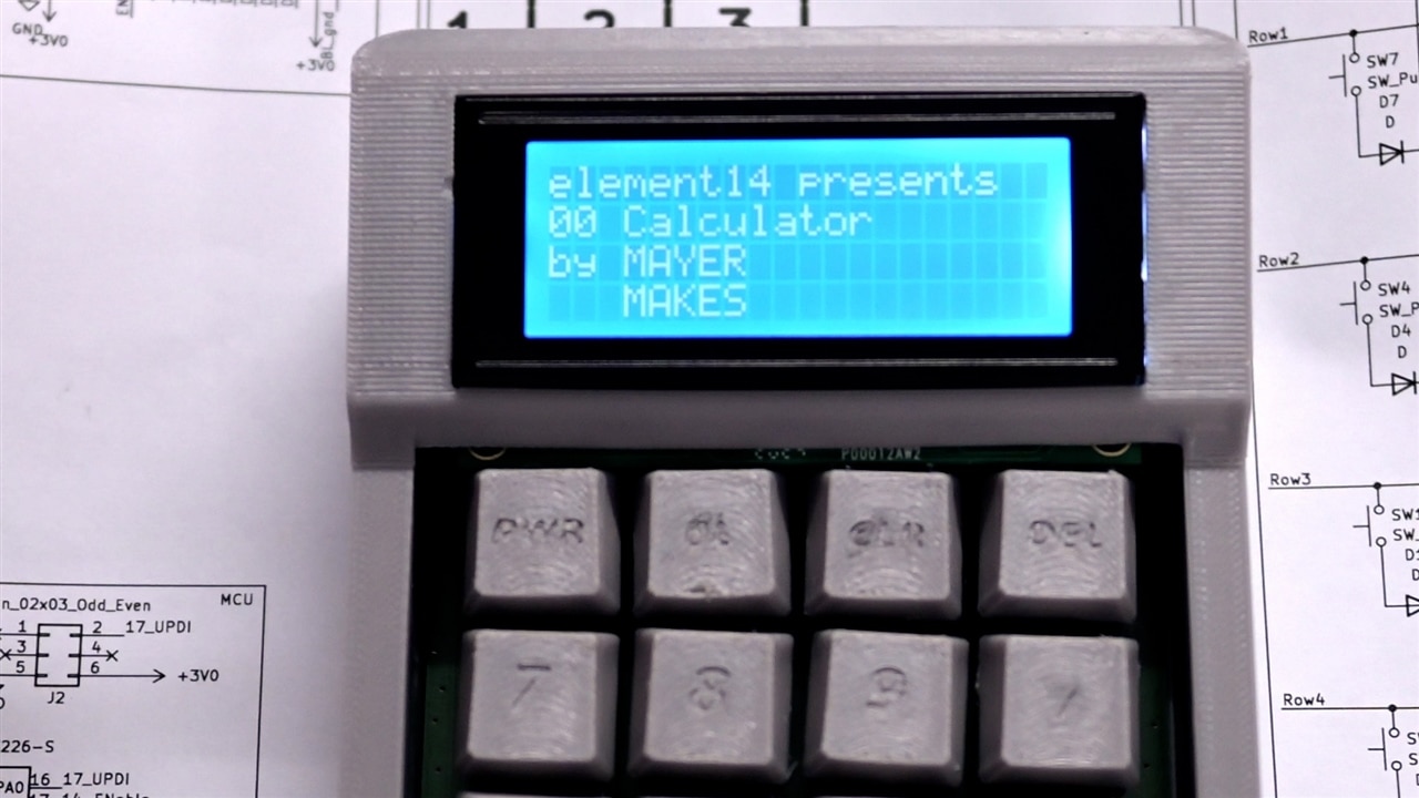
Clem (aka mayermakes) builds a fully open-source, battery-powered desktop calculator from scratch, powered by an ATtiny3226 micro-controller for efficient 3V operation. It features a 20x4 FORDATA LCD, Cherry MX key switches, and a custom PCB designed for matrix scanning with N-key rollover. The case combines a repurposed Multicomp Pro die-cast aluminium lid with 3D-printed PETG panels and key-caps. Programmed in Arduino using the Adafruit Keypad and Liquid Crystal libraries, the code handles basic four-function maths while showing the limits of an 8-bit system. All design files and source code are free to download for modification.

Watch the Project

You don't have permission to edit metadata of this video.
Edit media
x
image
Upload Preview
image

Building an Open-Source, Battery-Powered Desktop Calculator

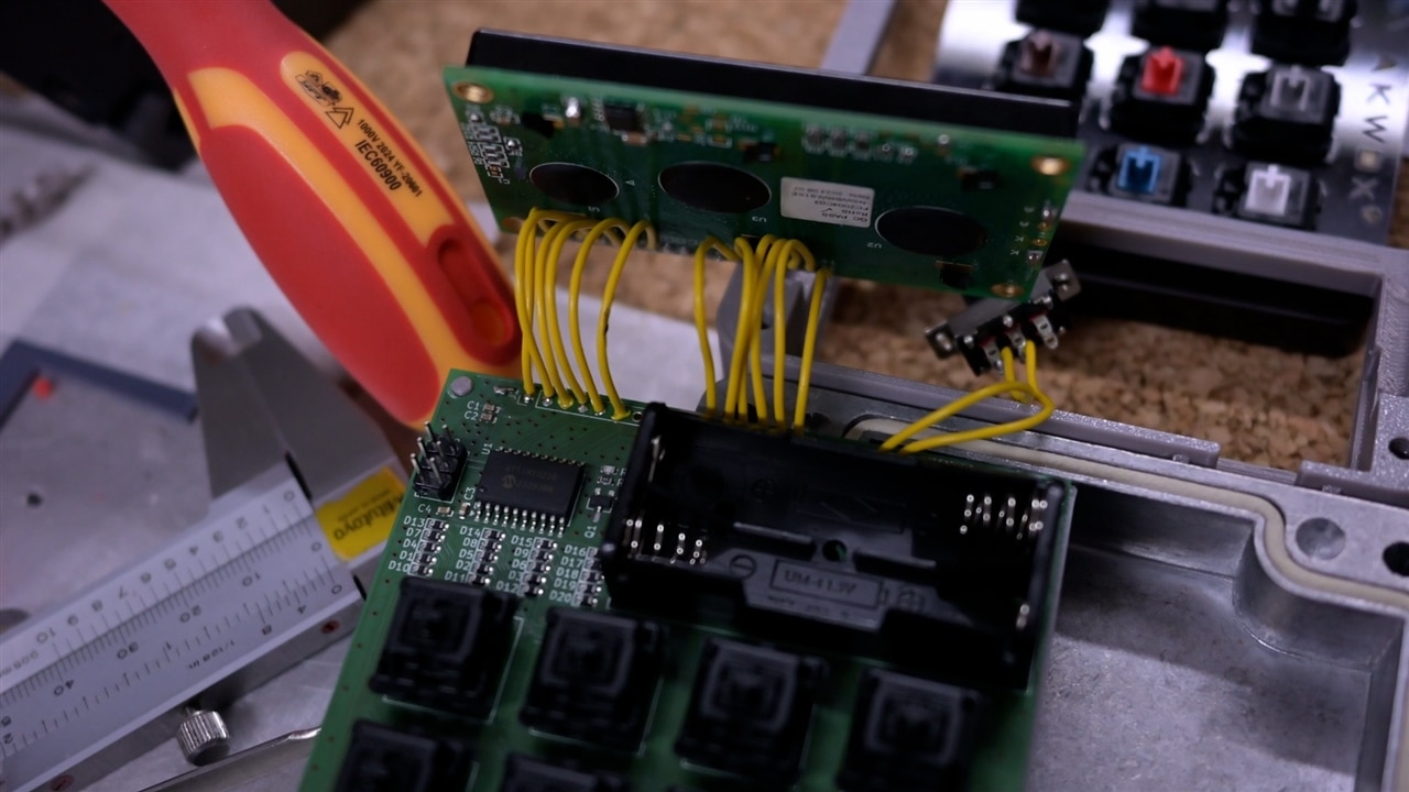
Clem Mayer’s latest project for element14 Presents is a modern take on the classic desk calculator,fully open-source, battery-powered, and designed from the ground up with both practicality and hackability in mind. Inspired by the large, sturdy adding machines he once used daily, Clem set out to create a compact but equally satisfying device that could be built and customized by anyone. His goals were clear: mechanical keys for fast entry, a robust and repairable body, low-power operation, and a design that invites modification. As always, he keeps things practical and budget-friendly, using smart component choices to make a fully functional device that’s perfect for DIYers.
Browsing Farnell

Choosing the Right Hardware - The Brains of the Build

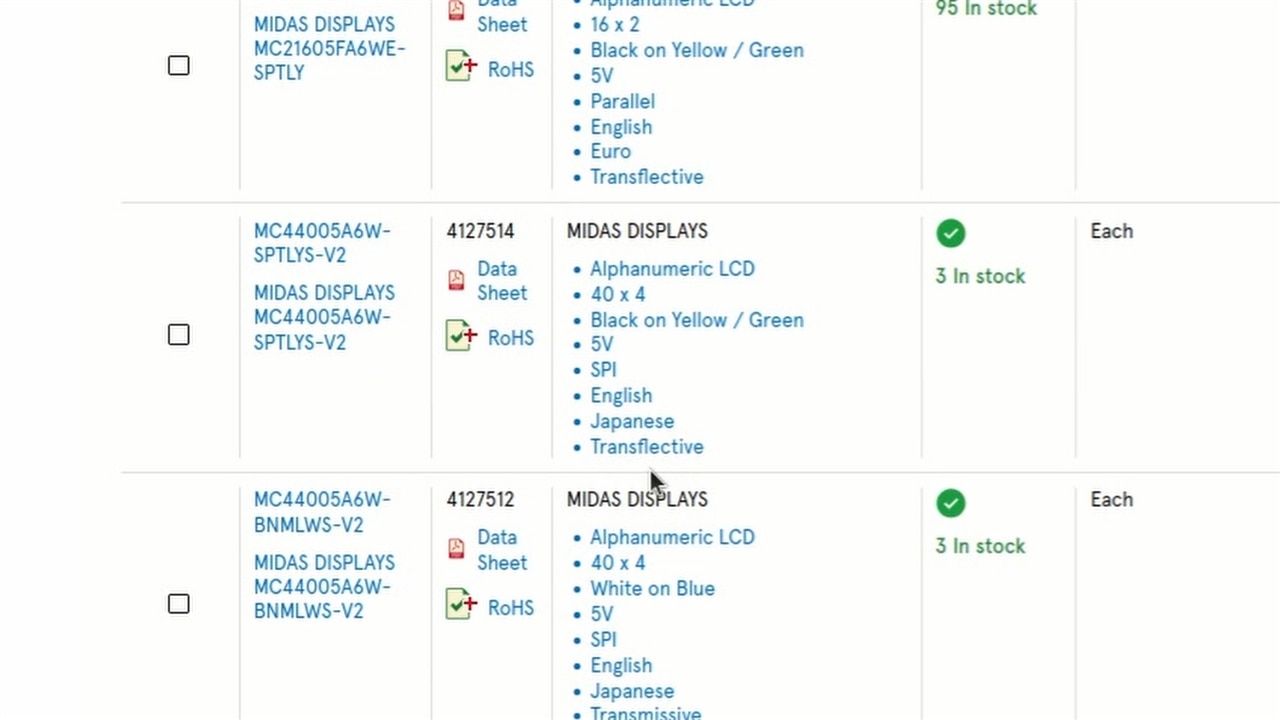
The heart of the build is an ATtiny3226 microcontroller, chosen not for raw processing power, but for its perfect match of features, pin count, and voltage range for this project. Running at 3V from two AAA batteries, the ATtiny3226 offers enough flash memory to comfortably accommodate the required Arduino libraries, unlike smaller ATtiny chips Clem has used in past projects. The keypad uses Cherry MX mechanical switches in a 4x5 diode-matrix layout, enabling N-key rollover without ghosting. For the display, Clem selected a 20x4 alphanumeric LCD from FORDATA, notable for being one of the few models that operates reliably at 3V. Together, these parts create a responsive, tactile, and low-power system suitable for everyday use. Since the whole thing runs on just 3V from two AAA batteries, every part had to be carefully picked to work within that power limit making the ATtiny3226 microcontroller, a solid choice for handling calculations while staying power-efficient.

The keys? Classic Cherry MX switches, giving that satisfying clicky feel that makes using the calculator a joy.
PCB Design

PCB and Building the Case

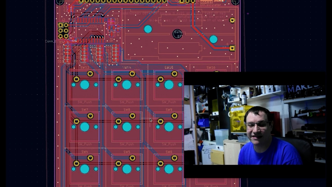
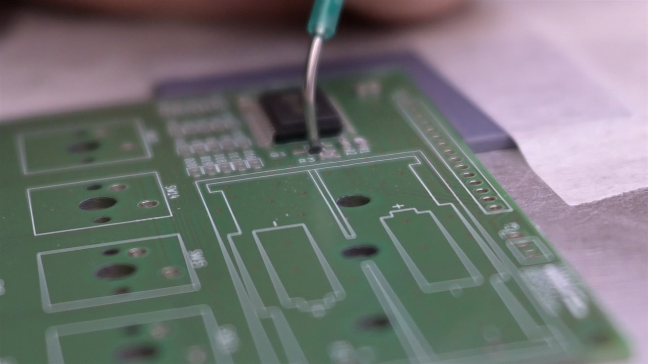
The custom PCB, designed in KiCad, routes the keypad matrix, display interface, and power circuitry in a clean, easily traceable layout. Diodes for the keys are grouped near the MCU for easier assembly and inspection. For the enclosure, Clem repurposed the lid of a Multicomp Pro die-cast aluminum box as a rigid base, topping it with a 3D-printed PETG shell and custom keycaps. This approach avoids costly custom milling while delivering a durable, repairable body. The aluminium base also ensures stability on the desk, and insulating spacers prevent shorts against the conductive surface. It’s super sturdy, way cheaper than custom milling, and leaves him with the rest of the box for another project. The front panel and buttons are 3D-printed in Multicomp PETG, and to keep things fun. All 3D models, including alternate keycap designs, are available for download below. 
PCBWiring

Code and Functionality

Programmed in the Arduino IDE, the calculator uses the Adafruit Keypad Library for scanning the button matrix and the LiquidCrystal Library for display control. The code processes basic four-function math, supports continuous operation entry (like traditional adding machines), and includes a delete function for correcting entries without clearing the entire calculation. Limitations of the 8-bit architecture are evident when handling large numbers,multiplying 65,535 by 65,535 demonstrates the maximum result it can display within its 8-bit limitations,yet these constraints provide an educational look at the boundaries of low-power microcontrollers. The code is fully open-source, inviting improvements such as expanded decimal handling, alternative display layouts, or additional functions.
Final Build

Final Thoughts and Future Possibilities

Clem’s desk calculator is more than a nostalgic gadget,it’s a showcase of thoughtful component selection, clever reuse of materials, and open-source accessibility. While some planned features, like backlight control via transistor, need refinement, the core design is stable, functional, and ready for others to build upon. Future iterations could experiment with different display types, rechargeable batteries, or expanded maths functions. As it stands, this project is a ready-made platform for learning about microcontroller programming, low-power electronics, and hardware design. Whether you want to build an everyday tool, a classroom teaching aid, or simply a satisfying DIY calculator, Clem’s design offers a solid starting point.

Like most of his projects, Clem shares all the files for free, encouraging others to build their own versions or tweak his design. To give it a final touch, he laser-engraves the back of the case, adding to its rugged, utilitarian look.

Clem’s DIY calculator isn’t just a cool gadget, it’s proof that with a bit of creativity and smart part choices, you can make something awesome from scratch. He’s hoping to see people remix his design and push it even further. So, who’s up for the challenge?

Bill of Materials

Product Name Manufacturer Quantity Buy Kit
MX1A-11NW CHERRY 16 Buy Now
ATTINY3226-SU MICROCHIP 1 Buy Now
2462 KEYSTONE 1 Buy Now
FC2004C03-NSWBBW-91SE FORDATA 1 Buy Now
TS391LT CHIP QUIK 1 Buy Now
TS391SNL CHIP QUIK 1 Buy Now
G116 MULTICOMP PRO 1 Buy Now
 

Supporting Links and Downloads

  •  Episode 678 Resources  
  • diy calculator
  • open source calculator
  • mechanical key calculator
  • arduino mechanical keyboard
  • DIY electronics project
  • arduino calculator
  • arudino lcd tutorial
  • custom pcb calculator
  • 20x4 lcd project
  • attiny3226 project
  • arduino keypad project
  • battery powered calculator
  • desk calculator build
  • cherry mx calculator
  • microcontroller calculator
  • Share
  • History
  • More
  • Cancel
Actions
  • Share
  • More
  • Cancel
  • Sign in to reply

Top Comments

  • mayermakes
    mayermakes 11 months ago +2
    I hope this gets a few people the itch to come up with their own custom stationary items!
  • mayermakes
    mayermakes 3 months ago in reply to e14 Contributor +1
    All the parts are in the Files you can download, the parts list on the page is just exemplary of the main components-> parts that don´t matter in their exact values are usually omited otherwise the blog…
  • mayermakes
    mayermakes 3 months ago in reply to e14 Contributor

    I think we’re talking past each other a bit here, so let me try to clarify calmly.

    First, I understand that this is your first PCB-level project and that it can feel overwhelming. That part is completely fair—moving from breadboards to schematics and full builds is a real step up, and it’s normal to run into gaps while learning.

    At the same time, I need to correct a few points factually. The components you mentioned (diodes, resistors, etc.) are not missing—they are present in the schematics, visible in the images, and referenced in the video and files. So the statement that they were “never mentioned” isn’t accurate.

    This project also isn’t structured as a step-by-step tutorial, and that’s intentional. It requires looking across multiple sources (schematics, files, video) and putting the pieces together. That process—figuring out implied parts and decisions—is exactly the skill you’re in the process of learning.

    When I mentioned “blindly following” or “paying attention,” it wasn’t meant as a personal attack or to say you will never learn. It was meant to describe the difference between following instructions line-by-line and actively working through the material. I can see how that wording came across more harshly than intended.

    From my perspective, the frustration started when the project was described as missing information, even though the information is there. That’s why I pushed back—because that claim doesn’t reflect the actual content provided.

    I’m not questioning that you’re putting in effort. But in this kind of project, part of the responsibility is to fully review the provided materials before concluding that something is missing. That step seems to have been incomplete here, which led to the misunderstanding.

    If you go back through the schematics and files carefully, you should be able to identify all required components and make it work. And if something is still unclear after that, asking specific questions will get you much further than assuming gaps in the design.

    I hope that clears up both the intent and the technical side.

    • Cancel
    • Vote Up 0 Vote Down
    • Sign in to reply
    • More
    • Cancel
  • e14 Contributor
    e14 Contributor 3 months ago in reply to mayermakes

    I can only speak to this interaction and it is not kind. You are the one who mentioned cheating so I addressed it. As far as beginners go, figuring out the implied pieces is something I am learning to do now. Instead of understanding that, you say I just didn't "pay attention". Also you accused me of "blindly following" and went so far as to say I will never learn, the most cruel of all. I am doing my best to truly understand, especially with this being the first project on a PCB. You did have kindness to share this in the first place but so much of your reply has been truly nasty.

    • Cancel
    • Vote Up 0 Vote Down
    • Sign in to reply
    • More
    • Cancel
  • mayermakes
    mayermakes 3 months ago in reply to e14 Contributor

    hold your horses. as with all on the web I assume the best intentions and beginner level.
    So first I go out of my way to provide you with an extensive answer to your unsubstantiated claim of missing information, out of kindness.

    Second  this statement is not implying you are cheating but a clear distinction of the type of project content I provide and a Tutorial(which none of my public projects are):
    image

    By building upon this project and what it provides you are not cheating but utilizing open source. It is already one of the easier to recreate open source projects on the web and has quite substantial information In the video/blog and Files, you just need to actually pay attention.

    I provided extensive reasoning on why my content is structured the way it is. For your benefit in a learning journey on electronics.
    You evidently did not watch the video and did not download the files and examine them:
    image

    All the information is in the video and the files which are both provided for free.

    I have shown more than enough kindness and reasoning in the actual project.

    I appreciate input especially valid critique from anyone and i have been on record for the last 10 years to be very kind with beginners.
    But I will not let unsubstantiated claims stand uncommented.

    here are the Files again linked for convenience: Episode 678 Resources
    same as above in the Blog text.
    look through them in detail and you will find all information needed to build the calculator. and I hope you can make use of the Knowledge in it in your electronics journey.

    Its hard to convey "kind language" over text.
    Taking the time, to give you the information you asked for  should be more than enough indication of my best intentions.


    • Cancel
    • Vote Up 0 Vote Down
    • Sign in to reply
    • More
    • Cancel
  • e14 Contributor
    e14 Contributor 3 months ago in reply to mayermakes

    That is a lot for you to assume it is cheating. The assignment was to talk about any subject. Actually making something is not required, but I made logic gate calculators on breadboards and am showing a different level abstraction with this calculator. I gave full credit and this is an intro to engineering as a discipline course not a technical class. I was giving input as a beginner. I hope you will treat people of different levels with more kindness, as we all started somewhere 

    • Cancel
    • Vote Up 0 Vote Down
    • Sign in to reply
    • More
    • Cancel
  • mayermakes
    mayermakes 3 months ago in reply to e14 Contributor

    All the parts are in the Files you can download, the parts list on the page is just exemplary of the main components-> parts that don´t matter in their exact values are usually omited otherwise the blog would be miles of resistors mainly, and errors can happen.
    you see the diodes in all the images and i mentioned them at multiple points in the video especially since the layout got quite clean.the video and documentation does mention everything you need to build a similar project but you have to put in the work yourself.
    These are not step by step tutorials as you correctly observed. they serve as inspiration and starting point for your own projects, and especially in a learning context you will gain the skills to make your own parts decissions - and things like the power switch are just salvaged from whatever I had laying around and you can do the same.
    If you look at the schematics you see all the parts and can quickly deduct what parts you need.
    Blindly following a step by step tutorial would nopt help you one bit in your electronics journey and in terms of a school project it would cross the line in the direction of cheating.
    you can make it work, just put in the work - and you will benefit from it long term.

    • Cancel
    • Vote Up +1 Vote Down
    • Sign in to reply
    • More
    • Cancel
  • e14 Contributor
    e14 Contributor 3 months ago

    Thank you for making this, but it has been so stressful to actually make this! I am making this for a school project. First off it says we need 16 keys, we need 20. Also the capacitors, diodes and resistors were never mentioned. Also what type of switch for on and off. I am so sad that I won't have a finished product even though I followed as closely as possible

    • Cancel
    • Vote Up 0 Vote Down
    • Sign in to reply
    • More
    • Cancel
  • mayermakes
    mayermakes 11 months ago in reply to dougw

    yep the soft power functions and backlight toggle I initialyl plant werent so dumb after all.

    • Cancel
    • Vote Up 0 Vote Down
    • Sign in to reply
    • More
    • Cancel
  • dougw
    dougw 11 months ago in reply to mayermakes

    As you indicate, it sounds like it might be useful to have the backlight automatically shut off and have the power button turn it back on.

    • Cancel
    • Vote Up 0 Vote Down
    • Sign in to reply
    • More
    • Cancel
  • mayermakes
    mayermakes 11 months ago in reply to dougw

    i did the video around April this year and used it sporadically, it still is functional but the backlight/screen gets a bit dim now. So the battery life was not to bad but could be a lot better with some tweaks in code and not keeping the backlight on at all times.

    • Cancel
    • Vote Up 0 Vote Down
    • Sign in to reply
    • More
    • Cancel
  • dougw
    dougw 11 months ago

    Cool project. About how long should this operate on a typical set of batteries?

    • Cancel
    • Vote Up 0 Vote Down
    • Sign in to reply
    • More
    • Cancel
>
element14 Community

element14 is the first online community specifically for engineers. Connect with your peers and get expert answers to your questions.

  • Members
  • Learn
  • Technologies
  • Challenges & Projects
  • Products
  • Store
  • About Us
  • Feedback & Support
  • FAQs
  • Terms of Use
  • Privacy Policy
  • Legal and Copyright Notices
  • Sitemap
  • Cookies

An Avnet Company © 2026 Premier Farnell Limited. All Rights Reserved.

Premier Farnell Ltd, registered in England and Wales (no 00876412), registered office: Farnell House, Forge Lane, Leeds LS12 2NE.

Follow element14

  • X
  • Facebook
  • linkedin
  • YouTube