

Join Natasha as she builds a custom LED matrix display from scratch, exploring the challenges of driving a large number of LEDs efficiently while keeping the design compact. She explains how she designed the PCB, tackled power distribution, and optimised the code to manage brightness and animations. Along the way, Natasha shares the lessons learned from debugging circuit issues, handling component tolerances, and ensuring the final project was both functional and visually impressive.
Watch the Project Build
Building an Audio Reactive LED Matrix with a Micro:bit
Natasha’s latest project brings together LEDs, audio analysis, and a micro:bit to create a compact music visualiser for her desk. The goal wasn’t just to build something visually pleasing, but also to test audio-reactive animations before applying them to her larger LED bike project. By prototyping with an 8x8 NeoPixel Matrix and an audio analyser, she could explore the process of mapping sound frequencies into light patterns in a controlled, small-scale environment.
“Before I go disconnecting wires and changing things on the main project, I wanted to create something small that I could keep on my desk while I’m experimenting with creating these audio reactive LED animations.” - Natasha
Turning Audio into Data
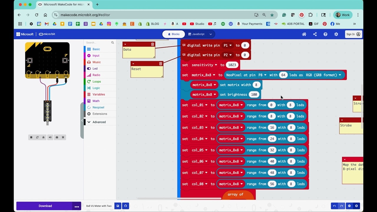
At the heart of the build is the audio analyser chip, which outputs values corresponding to different frequency bands. Unlike a raw microphone input, which only gives overall loudness, the analyser breaks the signal down into seven discrete ranges, from low bass through higher treble. This allows each column of the LED matrix to represent a band, creating a spectrum-style visualiser. These values are passed to the micro:bit and then mapped to LED columns on the matrix, creating a bar-style visualisation.
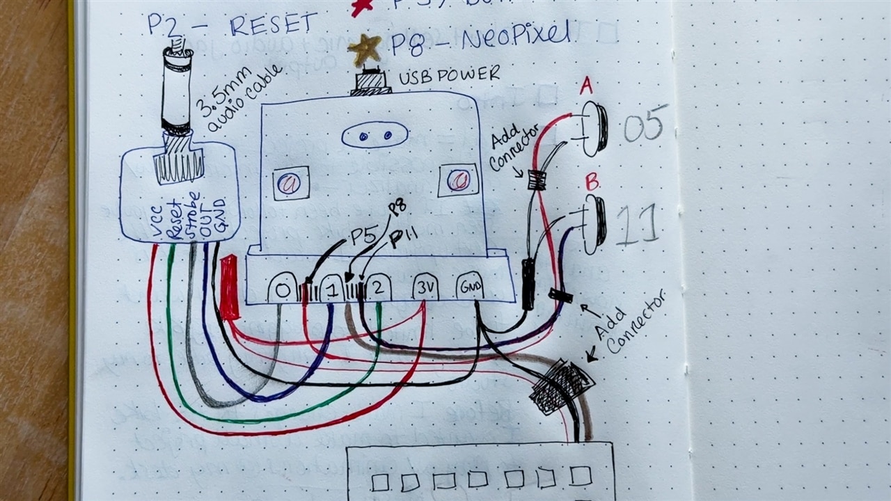
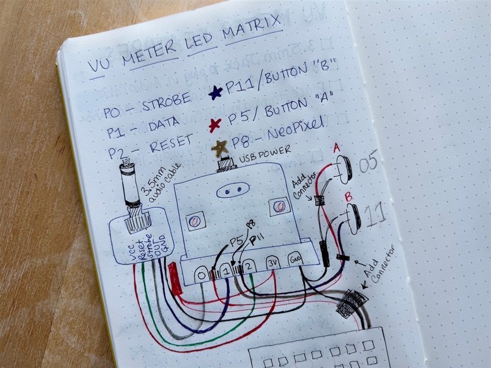
The pin connections were:
-
Reset → P2
-
Strobe → P0
-
Data → P1
-
NeoPixel → P8
Natasha wired up the analyser's strobe, data, and reset pins to the micro:bit. The reset clears the analyser before each new cycle, and the strobe triggers a new frequency sample. The micro:bit then reads the data line one band at a time. These values are stored in an array that links directly to the LED columns.
“There are three important pins on the audio analyser, a strobe pin, a data pin and a reset pin… and then I created a frequency array that was filled with the frequencies that the audio analyser will break the signal down into.” - Natasha
From there, she mapped the raw values to an LED range. Instead of scaling exactly from 0–8 LEDs (the height of the matrix), Natasha chose to shift the range slightly to leave some blank space at the bottom. This design choice made the animations more visually appealing by preventing the matrix from always being fully saturated with light.
Handling Sensitivity and Control
A common issue with audio-reactive projects is that different environments produce very different signal levels. A setup that looks great with loud music may show almost no response with quieter audio. To solve this, Natasha added sensitivity adjustment using the A and B buttons on the micro:bit. These buttons adjust the mapping scale so the animation looks consistent without needing to change speaker volume. Natasha initially considered using a potentiometer to adjust sensitivity, but found that MakeCode’s analogue read function introduced a 20ms delay, which was enough to make the animation appear choppy.
This kind of control is particularly useful when using the visualiser as a desk gadget. For example, when testing with her own voice through a microphone, the signal strength was much lower than music playback. By dialling up the sensitivity, she could still get smooth animations.
“If you are listening to quiet music, you don’t have to turn it up to get a really nice animation. You can actually just make it more sensitive or reduce the range that the audio is being displayed across.” - Natasha
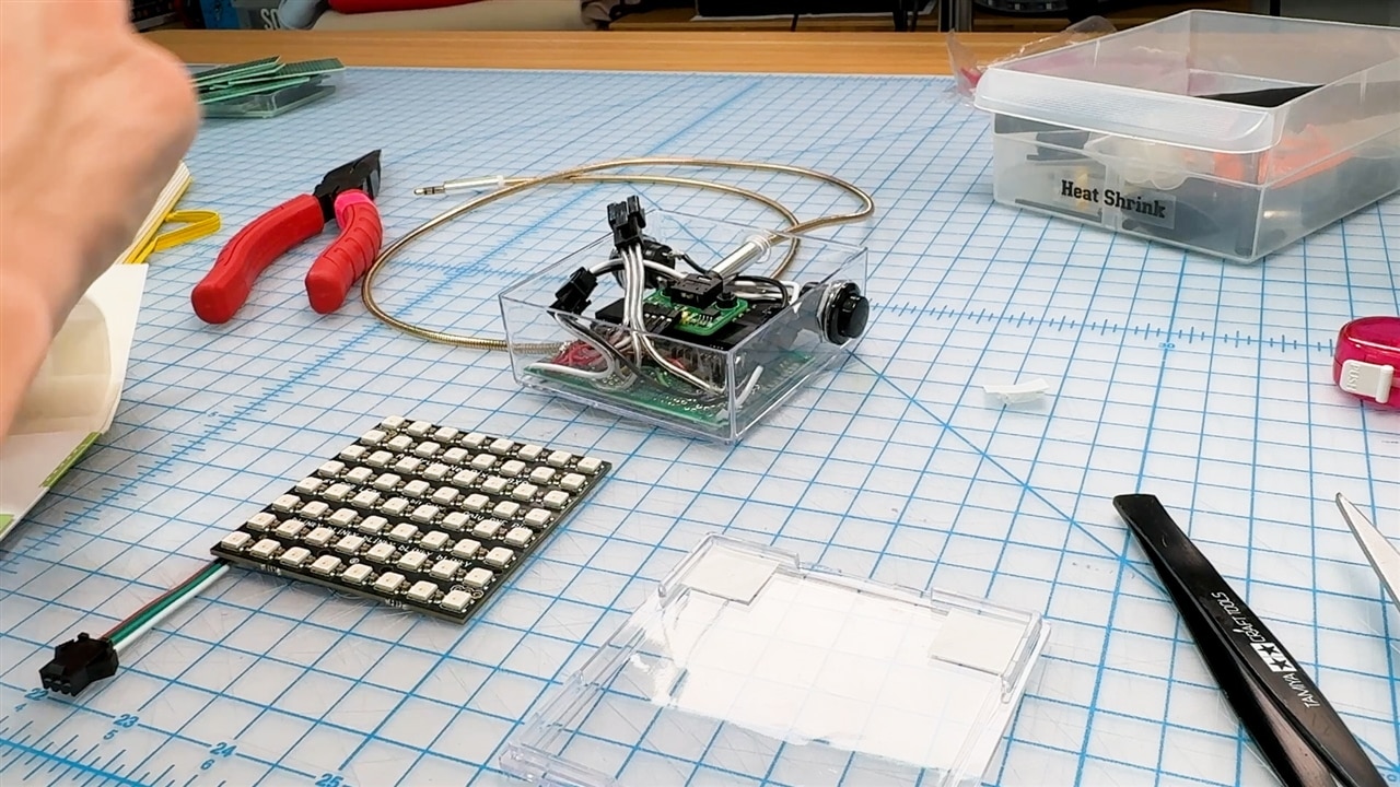
Fitting Hardware into a Compact Case
With the breadboard version working, Natasha turned to the mechanical side of the build: fitting all the parts into a small acrylic enclosure. She found a puck holder that fit the LED matrix perfectly, and planned to mount all other components inside the box. This quickly became a puzzle of component placement, cable routing, and mounting.
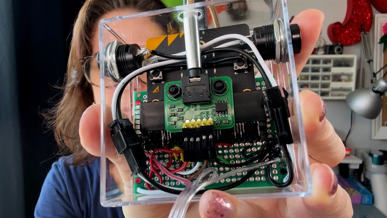
She marked drilling points on the clear acrylic using a Sharpie and her cutting mat grid. Being able to see through the box was an advantage, it made alignment much easier. The holes weren’t perfect, but they provided enough access for buttons, connectors, and wiring. Inside the box, she needed to accommodate the audio analyser, the micro:bit, and connectors for both USB power and a 3.5mm audio cable. Since the micro:bit’s onboard buttons would be inaccessible once enclosed, she added two external push-buttons, mounted through drilled holes in the case. These extend sensitivity control to the outside of the enclosure.
“Figuring out how to fit all of these components inside this acrylic box was a challenge. It took me a while to put all of the pieces in a configuration that it would work but I eventually got there.” - Natasha
The decision to use connectors for the LED matrix and buttons was deliberate. By doing so, Natasha ensured that the matrix could be removed and re-used in future projects, and the buttons could be replaced if needed. This kind of foresight is important in prototyping, keeping modules interchangeable helps when the design inevitably evolves.
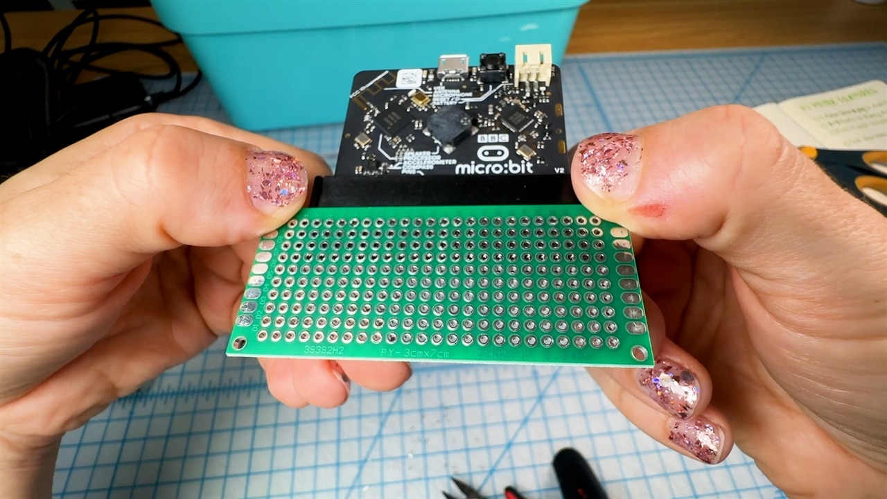
The Edge Connector Problem
One of the biggest technical hurdles came from the micro:bit edge connector adapter. Natasha planned to solder the pins onto perfboard, but discovered too late that the connector’s pins were staggered and didn’t align with standard 0.1” perfboard holes.
To work around this, she cut down the adapter, leaving only the front row of pins usable. This gave her access to about half the I/O lines she needed, but it made soldering extremely difficult. Without a proper breakout or custom PCB, she was forced to manually solder wires to tiny, closely-spaced pins—a process she describes as one of the hardest soldering sessions she’s ever attempted.
“This was probably one of the hardest soldering sessions I have ever had in my life. I do not recommend that you do this… Don’t DIY this way.” - Natasha
For others attempting a similar project, Natasha strongly advises buying a pre-made micro:bit breakout board, or designing a PCB specifically for the project. Her experience shows how much unnecessary complexity can come from forcing incompatible parts together. The soldering was messy and stressful, but functional. In hindsight, Natasha recommends that anyone replicating this project either buy a proper off-the-shelf breakout board or design a custom PCB, as the edge connector she used is really intended for PCB-mounted applications.
Debugging the Build
After the painful soldering process, powering up the device for the first time was nerve-wracking. At first, the LEDs didn’t react, confirming Natasha’s fear that her soldering might have failed. She retraced her wiring, checked the buttons, and confirmed the micro:bit was functioning. Finally, she realised the actual problem was much simpler: the audio cable wasn’t fully seated.
This moment highlights a common lesson in debugging electronics—start with the simplest possible issues before assuming a complex failure.
“That’s troubleshooting for you. Sometimes it is just the simple thing.” - Natasha
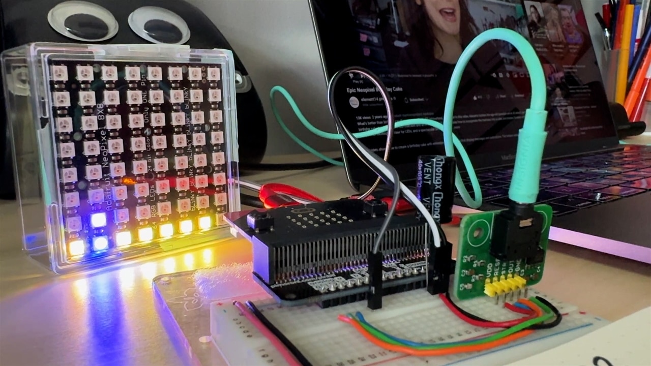
Once the cable was reconnected, the display worked perfectly, reacting not only to music but also to her own voice through a microphone feed.
Lessons Learned and Next Steps
The finished project works as a fun desktop accessory, producing smooth, adjustable animations from both music and live voice input. The sensitivity controls make it versatile in different environments, and the modular design with connectors leaves room for re-use. It demonstrates how the micro:bit can be paired with external hardware such as NeoPixels and audio analysers to create interactive displays without advanced coding.
For Natasha, the key takeaway is that while DIY solutions can sometimes get a project across the finish line, it’s often worth investing in proper breakout boards or designing a PCB to save hours of frustration. The soldering difficulty alone would justify that change in a future version.
This smaller-scale project also sets the stage for her larger ambition, making her LED bike project audio reactive. With the fundamental code, sensitivity handling, and data mapping solved, she can now scale the concept up to a more complex installation with multiple LED arrays.
“Next steps are creating more animations with my new desk toy. And then eventually integrating what I learned here into my larger bike project.” - Natasha
![]()
Supporting Links and Code Files
- micro:bit on the element14 Community
- micro:bit on the online stores
- micro:bit scratch code (web archive snapshot)
Related Content
- micro:bit project blogs (LED Bike Project)
Bill of Materials
| Product Name | Manufacturer | Quantity | Buy Kit |
|---|---|---|---|
| SBC, BBC MICRO:BIT SINGLE, V2.21, nRF52833 | BBC MICRO:BIT | 1 | Buy Now |
| RGB LED Pixel Matrix, NeoPixel NeoMatrix, 8x8, 64 LED's | ADAFRUIT | 1 | Buy Now |
| 2X40 RIGHT ANGLE EDGE CONNECTOR FOR MICRO:BIT | ADAFRUIT | 1 | Buy Now |
| AUDIO CABLE, 3.5MM PLUG, 0.2M, BLACK | ROLINE | 1 | Buy Now |
| Pushbutton Switch, Non-Latching, 12.2 mm, SPST-NO, Off-(On), Round, White | MULTICOMP PRO | 3 | Buy Now |
| Rotary Potentiometer, Cermet, 10 kohm, 1 Turns, Linear, 1 W, ± 10%, P16 Series | VISHAY | 2 | Buy Now |
| Soldering Fume Extractor with Filter Fume Extractor, Benchtop, ESD, 12 VDC | EDSYN | 1 | Buy Now |
Additional Parts
| Product Name | Manufacturer | Quantity |
|---|---|---|
| MSGEQ7 Seven Band Spectrum Analyzer Breakout Board | Neem Tech | 1 |
| BCW Hockey Puck Display Case Cube Holder 6-Pack, Crystal Clear, Stackable | BCW | 1 |
| ELEGOO 32 Pcs Double Sided PCB Board Prototype Kit for DIY Soldering with 5 Sizes Compatible with Arduino Kits | ELEGOO | 1 |
| UGlu Dash Sheets, 1/2 in. x 5/8 in. dashes | UGlu | 1 |
| Black Standoffs | Ghlmetf | 1 |
| Sparkfun micro:bit breakout | Sparkfun | 1 |
-

beacon_dave
-
Cancel
-
Vote Up
0
Vote Down
-
-
Sign in to reply
-
More
-
Cancel
Comment-

beacon_dave
-
Cancel
-
Vote Up
0
Vote Down
-
-
Sign in to reply
-
More
-
Cancel
Children