

In this project, Mark builds a simple but effective RFID-based access control system using an ESP32 and MFRC522 reader. The system can be programmed to recognise a specific RFID tag and trigger a relay or solenoid lock, making it ideal for securing enclosures, doors, or equipment. The video covers the full process, from circuit design and component selection to firmware setup and real-world installation, including mounting the reader behind glass and integrating a locking mechanism.
Get Locked In and Watch the Project Build
Building an RFID-Controlled Lock with ESP32
Mark’s project walks through a complete, working RFID access control system built around an ESP32 and a common MFRC522 reader. It’s positioned as a flexible foundation, something that can open a door, trigger a relay, or secure equipment, and the implementation reflects that balance between simplicity and practical use.
“Once you build it, you can use it to open a mechanical lock or control a relay… whatever you see fit.”
Parts Overview
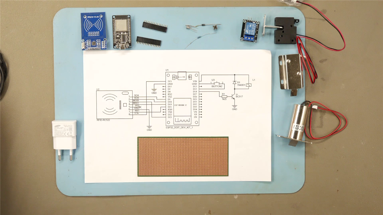
At its core, the system combines:
-
An ESP32 as the controller
-
An MFRC522 RFID reader for tag detection
-
A relay or solenoid lock for actuation
-
A transistor + flyback diode to safely drive inductive loads
-
A push button to enter programming mode
The design is intentionally minimal. As Mark puts it:
“And that’s all there is to it.”
That simplicity is one of the strengths of the project, there’s no unnecessary abstraction, just the essential building blocks required to make a usable access system.
Hardware Design Considerations
The circuit reflects a standard embedded control pattern: low-power logic controlling a higher-power actuator.
-
The transistor acts as a switch, allowing the ESP32 GPIO to control a 12V load.
-
The flyback diode protects against voltage spikes from the relay or solenoid coil:
“A diode that protects the transistor from the spikes that are generated by the coil.”
-
The button input enables runtime configuration without reflashing firmware.
Mark also explores different locking mechanisms,from small cabinet latches to larger solenoids, highlighting flexibility in real-world applications. Notably, all examples operate at 12V, which is a practical choice for readily available actuators.
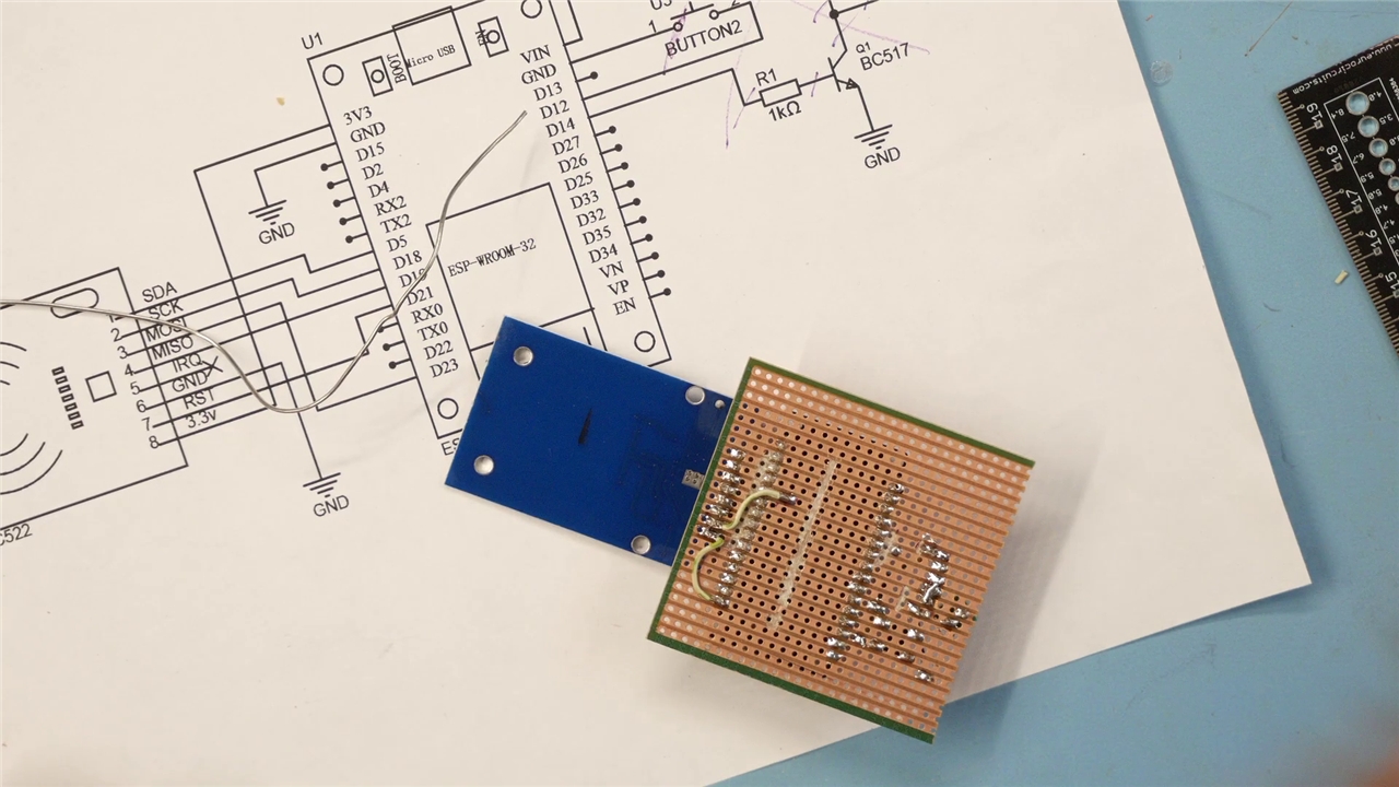
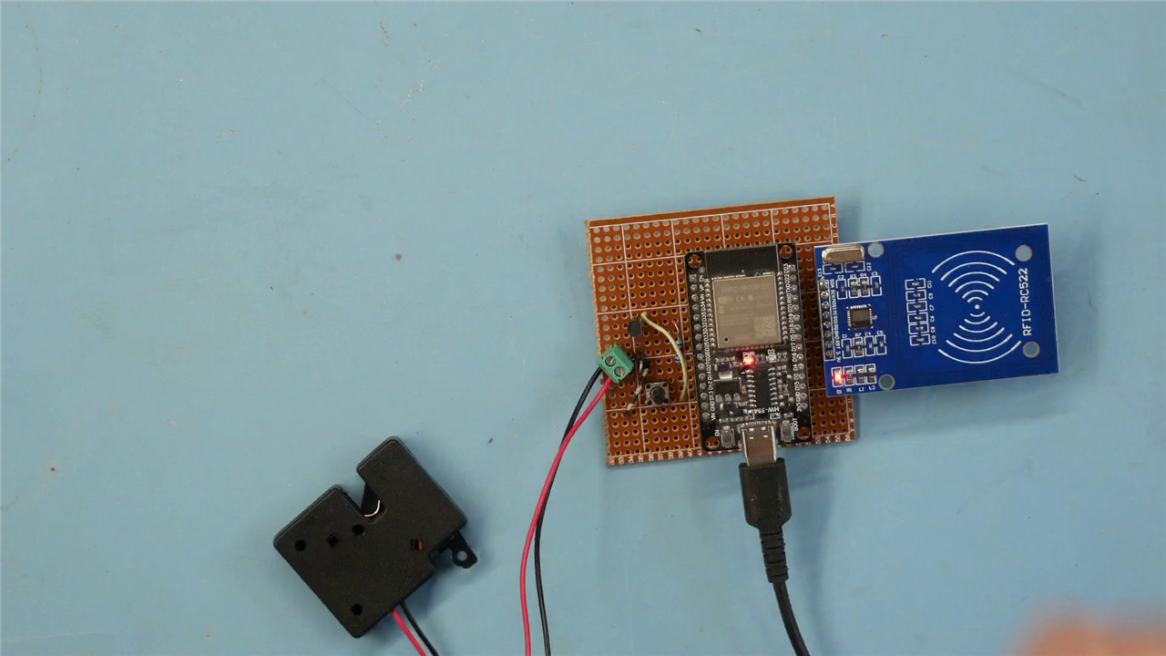
Physical Build and Layout
Rather than staying on a breadboard, Mark moves quickly into a semi-permanent build using perfboard. He physically trims the board to size:
“I use a knife… and I should be able to simply break it.”
This step is easy to overlook but important,it signals a transition from prototype to deployable hardware. The layout decisions (like diagonal placement due to pin pitch) are practical, not aesthetic. This is typical of fast, functional builds.
There are also moments where routing issues appear and are corrected:
“We solve that in a minute.”
That kind of iterative adjustment is realistic and useful for viewers attempting to replicate the project.
Firmware Architecture and Behaviour
The firmware is straightforward but well structured. It uses the MFRC522 library stack and EEPROM for persistence.
Libraries and setup
The project relies on:
-
MFRC522v2for RFID communication -
SPIfor hardware interface -
EEPROMfor non-volatile storage
Only one external install is required:
“You need to install… RFID MFRC522, version 2.”
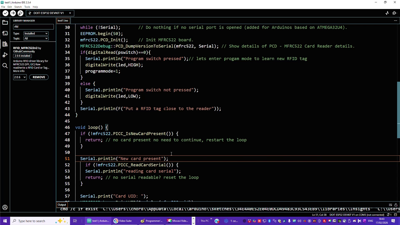
Key logic and code breakdown
1. Pin configuration and mode selection
#define relais 14
#define pswitch 12
#define led 2
char programmode=0;
-
Relay output on GPIO 14
-
Programming switch on GPIO 12
-
LED used as a status indicator
At boot, the system checks the button:
if(digitalRead(pswitch)==0){
  programmode=1;
}
This is a simple but effective pattern: boot-time mode selection avoids needing serial commands or UI.
2. RFID detection loop
The main loop exits early if no card is present:
if (!mfrc522.PICC_IsNewCardPresent()) {
  return;
}
This keeps execution efficient and avoids unnecessary processing.
Once a card is detected, its UID is read and converted:
String uidString = "";
for (byte i = 0; i < mfrc522.uid.size; i++) {
  if (mfrc522.uid.uidByte[i] < 0x10) {
    uidString += "0";
  }
  uidString += String(mfrc522.uid.uidByte[i], HEX);
}
This conversion step is important, it ensures a consistent string format for comparison.
3. EEPROM storage and comparison
The system uses EEPROM to store a single authorised UID:
EEPROM.writeString(0,uidString);
EEPROM.commit();
And later compares it:
if (uidString == EEPROM.readString(0)){
  digitalWrite(relais, HIGH);
}
Mark summarises the behaviour clearly:
“If there is a match, then it will open the door or activate the relay.”
Design observations, Limitations and Future Improvements
-
Single UID storage keeps the logic simple but limits scalability
-
EEPROM use is appropriate for persistence across resets
-
The 3-second relay activation (
delay(3000)) is fixed, this could be parameterised
The final application is a practical one: securing a 3D printer enclosure.
“I do have a curious kid… this way I can prevent her from opening it.”
Mark hints at broader applications but doesn’t extend the design further. There are several obvious next steps:
1. Multiple user support
Currently only one UID is stored. Expanding to a list would make this viable for shared access.
2. Security considerations
-
UID-based authentication can be cloned on some tags
-
No encryption or challenge-response mechanism
3. Feedback and UX
-
Add buzzer or LED patterns for success/failure
-
Serial output is useful but not user-facing
4. Power and enclosure
-
No dedicated enclosure or power regulation shown
-
Long-term installs would need proper housing
This project does exactly what it sets out to do: deliver a working RFID-controlled lock with minimal overhead. It’s approachable, adaptable, and grounded in real use rather than theory.
The combination of ESP32, MFRC522, and a simple transistor driver is well understood—but Mark’s implementation shows how quickly that can become something practical.
“Present my ring… and it will open.”
That direct cause-and-effect is what makes the project useful, and easy to build upon.
Supporting Files and Links
Bill of Materials
| Product Name | Manufacturer | Quantity | Buy Kit |
|---|---|---|---|
| WURTH ELEKTRONIK Tactile Switch, WS-TATV Series, Top Actuated, Through Hole, Round Button | WURTH ELEKTRONIK | 1 | Buy Now |
| Transistor BC517-D74Z | Onsemi | 1 | Buy Now |
| Resistor 1K | Multicomp pro | 1 | Buy Now |
| Diode 1n4001 | Onsemi | 1 | Buy Now |
| RFID Tag KW9Z-T1X5B | IDEC | 1 | Buy Now |
| Product Name | Manufacturer | Quantity | |
| ESP32 Doit Devkit V1 | |||
| RFID reader PCB develp. Kit RC522 | |||
| USB cable and USB power supply | |||
| Lock mechanism 5V | BADODO Security | 1 | |
Top Comments