element14 Community
element14 Community
    Register Log In
  • Site
  • Search
  • Log In Register
  • About Us
  • Community Hub
    Community Hub
    • What's New on element14
    • Feedback and Support
    • Benefits of Membership
    • Personal Blogs
    • Members Area
    • Achievement Levels
  • Learn
    Learn
    • Ask an Expert
    • eBooks
    • element14 presents
    • Learning Center
    • Tech Spotlight
    • STEM Academy
    • Webinars, Training and Events
    • Learning Groups
  • Technologies
    Technologies
    • 3D Printing
    • FPGA
    • Industrial Automation
    • Internet of Things
    • Power & Energy
    • Sensors
    • Technology Groups
  • Challenges & Projects
    Challenges & Projects
    • Design Challenges
    • element14 presents Projects
    • Project14
    • Arduino Projects
    • Raspberry Pi Projects
    • Project Groups
  • Products
    Products
    • Arduino
    • Avnet Boards Community
    • Dev Tools
    • Manufacturers
    • Multicomp Pro
    • Product Groups
    • Raspberry Pi
    • RoadTests & Reviews
  • Store
    Store
    • Visit Your Store
    • Choose another store...
      • Europe
      •  Austria (German)
      •  Belgium (Dutch, French)
      •  Bulgaria (Bulgarian)
      •  Czech Republic (Czech)
      •  Denmark (Danish)
      •  Estonia (Estonian)
      •  Finland (Finnish)
      •  France (French)
      •  Germany (German)
      •  Hungary (Hungarian)
      •  Ireland
      •  Israel
      •  Italy (Italian)
      •  Latvia (Latvian)
      •  
      •  Lithuania (Lithuanian)
      •  Netherlands (Dutch)
      •  Norway (Norwegian)
      •  Poland (Polish)
      •  Portugal (Portuguese)
      •  Romania (Romanian)
      •  Russia (Russian)
      •  Slovakia (Slovak)
      •  Slovenia (Slovenian)
      •  Spain (Spanish)
      •  Sweden (Swedish)
      •  Switzerland(German, French)
      •  Turkey (Turkish)
      •  United Kingdom
      • Asia Pacific
      •  Australia
      •  China
      •  Hong Kong
      •  India
      •  Korea (Korean)
      •  Malaysia
      •  New Zealand
      •  Philippines
      •  Singapore
      •  Taiwan
      •  Thailand (Thai)
      • Americas
      •  Brazil (Portuguese)
      •  Canada
      •  Mexico (Spanish)
      •  United States
      Can't find the country/region you're looking for? Visit our export site or find a local distributor.
  • Translate
  • Profile
  • Settings
WorkBench Wednesdays
  • Challenges & Projects
  • element14 presents
  • WorkBench Wednesdays
  • More
  • Cancel
WorkBench Wednesdays
Documents Do ALL Scope Probes Need Ground? - Workbench Wednesdays 55
  • Blog
  • Forum
  • Documents
  • Quiz
  • Events
  • Polls
  • Files
  • Members
  • Mentions
  • Sub-Groups
  • Tags
  • More
  • Cancel
  • New
Join WorkBench Wednesdays to participate - click to join for free!
Actions
  • Share
  • More
  • Cancel
Engagement
  • Author Author: tariq.ahmad
  • Date Created: 11 May 2022 9:26 PM Date Created
  • Last Updated Last Updated: 25 May 2022 7:24 AM
  • Views 134609 views
  • Likes 6 likes
  • Comments 9 comments
Related
Recommended

Do ALL Scope Probes Need Ground? - Workbench Wednesdays 55

You don't have permission to edit metadata of this video.
Edit media
x
image
Upload Preview
image


When connecting multiple oscilloscope probes to a circuit, does each probe need to connect to ground? The short answer is yes! Why? The long answer is kind of. Why? Because of the ground loop. Connecting ground shortens the ground loop, resulting in better measurements. James shows what happens when you do not use proper ground connections. And leaves you with a viewer challenge.

image

Answer to View Challenge:

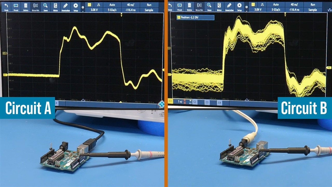
In the video, James showed the above image and asked: what is the difference between the two? For context, it is the same scope settings, probe, Arduino, and code. Neither has the probe’s ground connected. So then why are the two waveforms SO different?
Before you see the answer, these are NOT the reason for the difference:

-The difference is power supply quality.
-One uses onboard Arduino regulator, the other does not.

Final hint: If the probe ground is connected for either circuit, then the waveform is a clean square wave like we saw at the start of the video.
The Answer:
Highlight the text below to make it readable:

The short answer is: Earth grounding.
As most people noticed, the core difference is that Circuit A was powered by USB while Circuit B is powered by the barrel jack. The barrel jack was a little bit of a red herring. If you did not notice earlier in the video, the barrel is powered by the bench power supply. (However, if it was a wall-wart, the result would be similar.)
The USB supply came from an instrument (or PC) connected to the wall with an Earth ground tab. (The oscilloscope, like most scopes, is also connected to Earth ground.) The bench power supply’s output channels are isolated (or floating) from Earth ground!
So, Circuit A is finding a ground path through the earth ground connection of the USB supply and the scope. While Circuit B is likely to find a path through the Neutral/Ground connection back at my electrical box.

Supplemental Content:

  • WorkBench Wednesdays #47: What is Oscilloscope Bandwidth?
  • WorkBench Wednesdays #42: Compare Ideal vs. Real Filter with an LCR Meter
  • Tektronix: Application note for Fundamentals of Floating Measurements and Isolated Input Oscilloscopes

Bill of Materials

Product Name Manufacturer Quantity Buy Kit
RTM3000 - 4 Channel Oscilloscope (RTM3K-COM4) Rohde & Schwarz 1 Buy Now
TPS2012B - 2 Channel Isolated 100 MHz Oscilloscope Tektronix 1 Buy Now
[Bundle] Development Kit, Analog Discovery 2 Pro Bundle, 30MHz Oscilloscope, 12MHz Waveform Generator Digilent 1 Buy Now
RTH1054, 500 MHz, 4 Analog, 8 Digital, 5 Gsps, complete Rohde & Schwarz 1 Buy Now


element14 presents

element14 Presents  |  About James|  Workbench Wednesdays

  • Ground loop
  • Oscilloscope probes
  • Scope ground
  • Probe ground
  • Scope probe ground
  • james
  • wbw
  • Share
  • History
  • More
  • Cancel
  • Sign in to reply
  • koudelad
    koudelad over 3 years ago in reply to baldengineer

    It is really easy to use, we will see, how it holds over time.

    I can see two Dupont adapters - one is "needle probe to Dupont" (for example for direct connection to Analog Discovery, Saleae etc) or .Dupont to banana, which could be used for a connection to a bench power supply or multimeter as a "needle probe - Dupont (receptable) - pin header - Dupont (receptable) - banana connector).

    • Cancel
    • Vote Up 0 Vote Down
    • Sign in to reply
    • More
    • Cancel
  • baldengineer
    baldengineer over 3 years ago in reply to koudelad

    Interesting. I'd prefer to find something that uses existing probes since I have piles of them. But, their system looks relatively easy to use.

    I didn't understand their Dupont adapter. Do they have a Dupont / Square-pin adapter for the scope probe?

    • Cancel
    • Vote Up 0 Vote Down
    • Sign in to reply
    • More
    • Cancel
  • koudelad
    koudelad over 3 years ago in reply to koudelad

    image

    • Cancel
    • Vote Up 0 Vote Down
    • Sign in to reply
    • More
    • Cancel
  • koudelad
    koudelad over 3 years ago

    Regarding the oscilloscope probe holders, I would recommend PCBite from Sensepeek. We tried them at Embedded World conference and ordered them right after we got back into the office. We bought a few sets (for each HW developer) and are happily using it.

    • Cancel
    • Vote Up 0 Vote Down
    • Sign in to reply
    • More
    • Cancel
  • colporteur
    colporteur over 3 years ago

    Great presentation. Seeing is believing.

    Me thinks, the challenge answer has to do with how the boards are powered.

    • Cancel
    • Vote Up 0 Vote Down
    • Sign in to reply
    • More
    • Cancel
  • baldengineer
    baldengineer over 3 years ago in reply to Ravi-teja.

    To be clear, the left Arduino is not connected to the Oscilloscope. It is connected to a separate computer for power.

    • Cancel
    • Vote Up 0 Vote Down
    • Sign in to reply
    • More
    • Cancel
  • Ravi-teja.
    Ravi-teja. over 3 years ago

    Ground is ground in anywhere on a circuit board,i think  there are not relation between power supply ground and usb ground (scope ground) in picture B,in this picture A scope ground is internal connected with usb ground.

    • Cancel
    • Vote Up 0 Vote Down
    • Sign in to reply
    • More
    • Cancel
  • baldengineer
    baldengineer over 3 years ago in reply to kl0s7388

    Sorry, no that is not why.

    If it were the reason, it would not explain why connecting the probe's ground results in "good" measurements on both.

    • Cancel
    • Vote Up 0 Vote Down
    • Sign in to reply
    • More
    • Cancel
  • kl0s7388
    kl0s7388 over 3 years ago

    Looks like the two supply cables are different, one is shielded the other is simply a two-wire connection acting as an antenna.

    73 - Dino KLØS

    • Cancel
    • Vote Up 0 Vote Down
    • Sign in to reply
    • More
    • Cancel
element14 Community

element14 is the first online community specifically for engineers. Connect with your peers and get expert answers to your questions.

  • Members
  • Learn
  • Technologies
  • Challenges & Projects
  • Products
  • Store
  • About Us
  • Feedback & Support
  • FAQs
  • Terms of Use
  • Privacy Policy
  • Legal and Copyright Notices
  • Sitemap
  • Cookies

An Avnet Company © 2025 Premier Farnell Limited. All Rights Reserved.

Premier Farnell Ltd, registered in England and Wales (no 00876412), registered office: Farnell House, Forge Lane, Leeds LS12 2NE.

ICP 备案号 10220084.

Follow element14

  • X
  • Facebook
  • linkedin
  • YouTube