When connecting multiple oscilloscope probes to a circuit, does each probe need to connect to ground? The short answer is yes! Why? The long answer is kind of. Why? Because of the ground loop. Connecting ground shortens the ground loop, resulting in better measurements. James shows what happens when you do not use proper ground connections. And leaves you with a viewer challenge.

Answer to View Challenge:
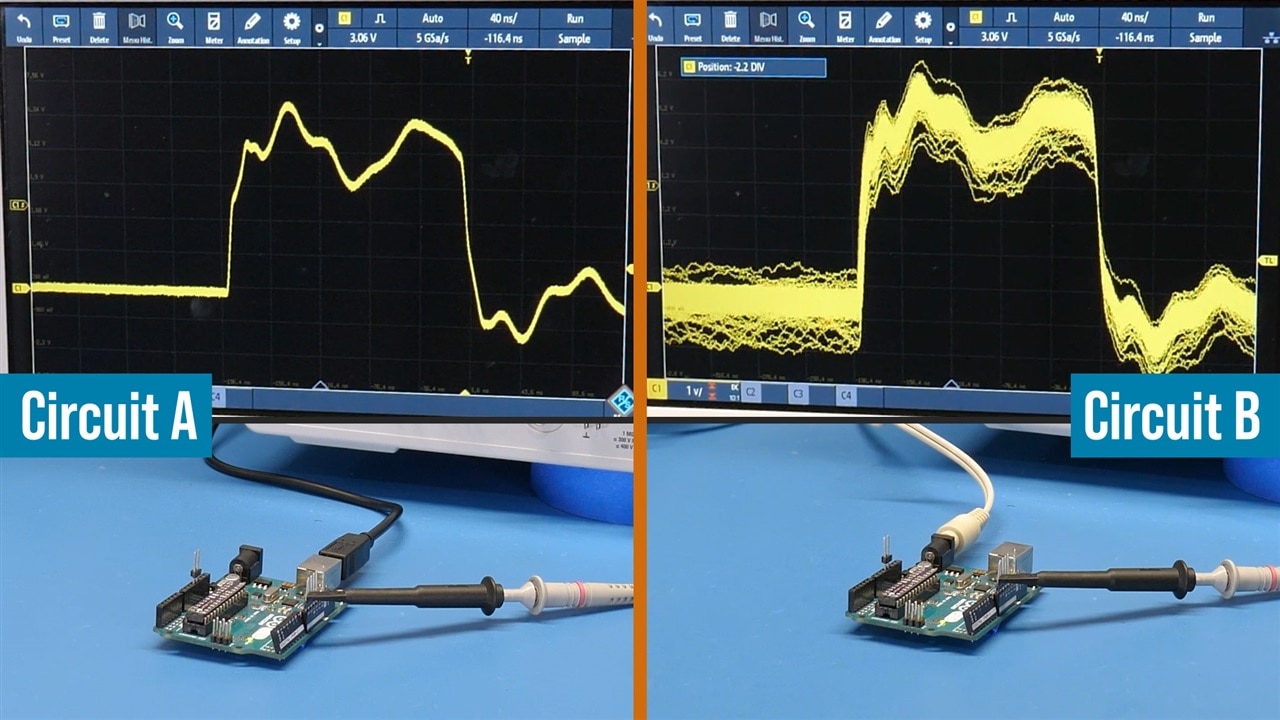
In the video, James showed the above image and asked: what is the difference between the two? For context, it is the same scope settings, probe, Arduino, and code. Neither has the probe’s ground connected. So then why are the two waveforms SO different?
Before you see the answer, these are NOT the reason for the difference:
Before you see the answer, these are NOT the reason for the difference:
-The difference is power supply quality.
-One uses onboard Arduino regulator, the other does not.
Final hint: If the probe ground is connected for either circuit, then the waveform is a clean square wave like we saw at the start of the video.
The Answer:
Highlight the text below to make it readable:
The short answer is: Earth grounding.
As most people noticed, the core difference is that Circuit A was powered by USB while Circuit B is powered by the barrel jack. The barrel jack was a little bit of a red herring. If you did not notice earlier in the video, the barrel is powered by the bench power supply. (However, if it was a wall-wart, the result would be similar.)
The USB supply came from an instrument (or PC) connected to the wall with an Earth ground tab. (The oscilloscope, like most scopes, is also connected to Earth ground.) The bench power supply’s output channels are isolated (or floating) from Earth ground!
So, Circuit A is finding a ground path through the earth ground connection of the USB supply and the scope. While Circuit B is likely to find a path through the Neutral/Ground connection back at my electrical box.
Supplemental Content:
- WorkBench Wednesdays #47: What is Oscilloscope Bandwidth?
- WorkBench Wednesdays #42: Compare Ideal vs. Real Filter with an LCR Meter
- Tektronix: Application note for Fundamentals of Floating Measurements and Isolated Input Oscilloscopes
Bill of Materials
| Product Name | Manufacturer | Quantity | Buy Kit |
|---|---|---|---|
| RTM3000 - 4 Channel Oscilloscope (RTM3K-COM4) | Rohde & Schwarz | 1 | Buy Now |
| TPS2012B - 2 Channel Isolated 100 MHz Oscilloscope | Tektronix | 1 | Buy Now |
| [Bundle] Development Kit, Analog Discovery 2 Pro Bundle, 30MHz Oscilloscope, 12MHz Waveform Generator | Digilent | 1 | Buy Now |
| RTH1054, 500 MHz, 4 Analog, 8 Digital, 5 Gsps, complete | Rohde & Schwarz | 1 | Buy Now |

