How do you pick I2C pull-up resistor values? The common response is to choose anything between 1 kOhm and 10 kOhm. But, still, how do you know the best value? The answer is related to the maximum number of devices you can have without using a repeater, switch, or multiplexer on an I2C bus. Many people would answer a number like 127 since that is how many 7-bit addresses are available. However, creating an I2C bus with more than 20 or so devices is nearly impossible. Why? Because the bus capacitance matters most–which is also the key to determining I2C pull-up resistor values!
Watch the Video:
Downloads & Links | Bill of Material | Discussion

James was looking for application notes about picking I2C pull-up resistor values. One that caught his attention was from Texas Instruments. I2C Bus Pullup Resistor Calculation (SLVA689) covers calculating the maximum and minimum pull-up values. It also clearly shows the math for the rise time calculation and bus capacitance. James created an online spreadsheet with pre-configured equations to make things easier for you.
Application notes from many other vendors and tutorials on the web have a similar example as the TI app note. It comes up with the ridiculous range of 966.667 to 1770 ohms. As James says in the video, the only sane value in that range is 1 kOhm. (Although there are a couple of other E12 and E24 values too!) But if that's the usable range, how do other I2C devices use 2.2, 4.7, or 10 kOhm kOhm work?!
Key I2C Numbers to Know
We need to know some key information about the I2C specification. James uses a DesignCon 2003 presentation, but these numbers are also available in the full I2C spec. The two most common speeds for I2C are 100 kbit/s and 400 kbit/s. Later in the video, James uses an OLED screen running at 400 kbits/s, so most of the video centers around the faster speed.
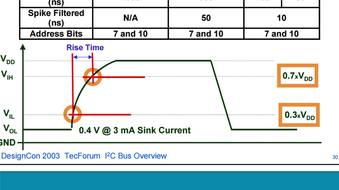
The maximum bus capacitance allowed on I2C for both speeds is 400 picofarads. The maximum rise time of the bus is limited to 1000 nanoseconds and 300 nanoseconds, respectively, depending on the bus speed. Last, it is essential to know that the spec uses the 30% and 70% points of the edge to determine rise time.

I2C devices need a pull-up resistor because they use an open-drain (or open-collector) architecture. This setup means a device only drives the bus to ground, effectively letting it float when it wants to represent a logic high. When the bus goes high, the pull-up resistor and the bus capacitance limit the signal's rise time. We see sloped edges on the rise and sharp edges on the fall of I2C waveforms because the two components form an RC network!
Measuring I2C Bus Capacitance
Estimating I2C bus capacitance has a few issues. Not all I2C devices define their input capacitance. And you need a good model for the interconnects. A far simpler method is to measure it on an actual circuit. James uses an Arduino Uno and an SSD1306-based OLED on a breadboard connected with wires as an example.
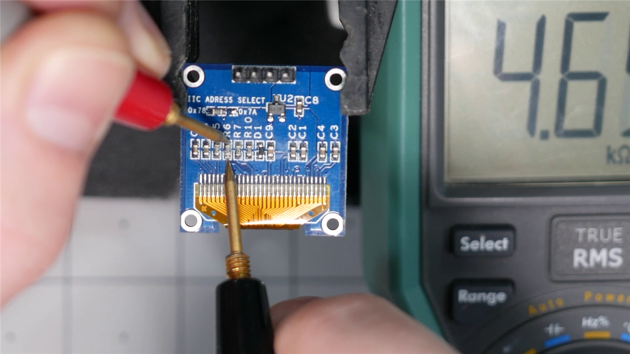
On the back of these OLEDs are 4.7 kOhm pull-up resistors on both the SDA and SCL lines.
James assumed that SCL and SDA should look very similar, so most measurements only look at SCL. The initial rise time measurement is 534 nanoseconds! The display works, but this value is way outside of the I2C's spec of 300 nanoseconds for a 400 kHz bus. However, most oscilloscopes default to the 10-90 points of the rise time. After changing the reference levels to use 30-70, the rise time comes out to be 193 nanoseconds.

Using the 4.7 kOhm pull-up resistor value and the 193 nanosecond rise time, James shows how to calculate the effective bus capacitance using the equations in the TI app note. This math is where the spreadsheet comes in handy! It turns out the bus capacitance is 48 picofarads.

For most designs, this verification step is the endpoint. Both the rise time and bus capacitance are well below the I2C spec! We have verified this bus is in compliance and could move on. However, James points out that we did ignore one other resistor on the bus: the Arduino's internal pull-up!
Arduino Internal Pull-Ups
Nearly all microcontroller GPIO pins offer an internal pull-up resistor. The values of these resistors are usually in the 20 to 50 kilohm range. (They are not actual resistors on the silicon. They're the resistance of a MOSFET's drain-to-source channel. But that's a topic for a different video.)
The Arduino's I2C library, also called "Wire" or "Two-Wire Interface (TWI), enables the internal pull-ups for the I2C pins. James did not consider the internal pull-up when he showed the rise time calculations. An interesting side-effect of a 5V Arduino Uno using its internal pull-up resistor is that it makes the bus compatible with a 3.3 volt device.
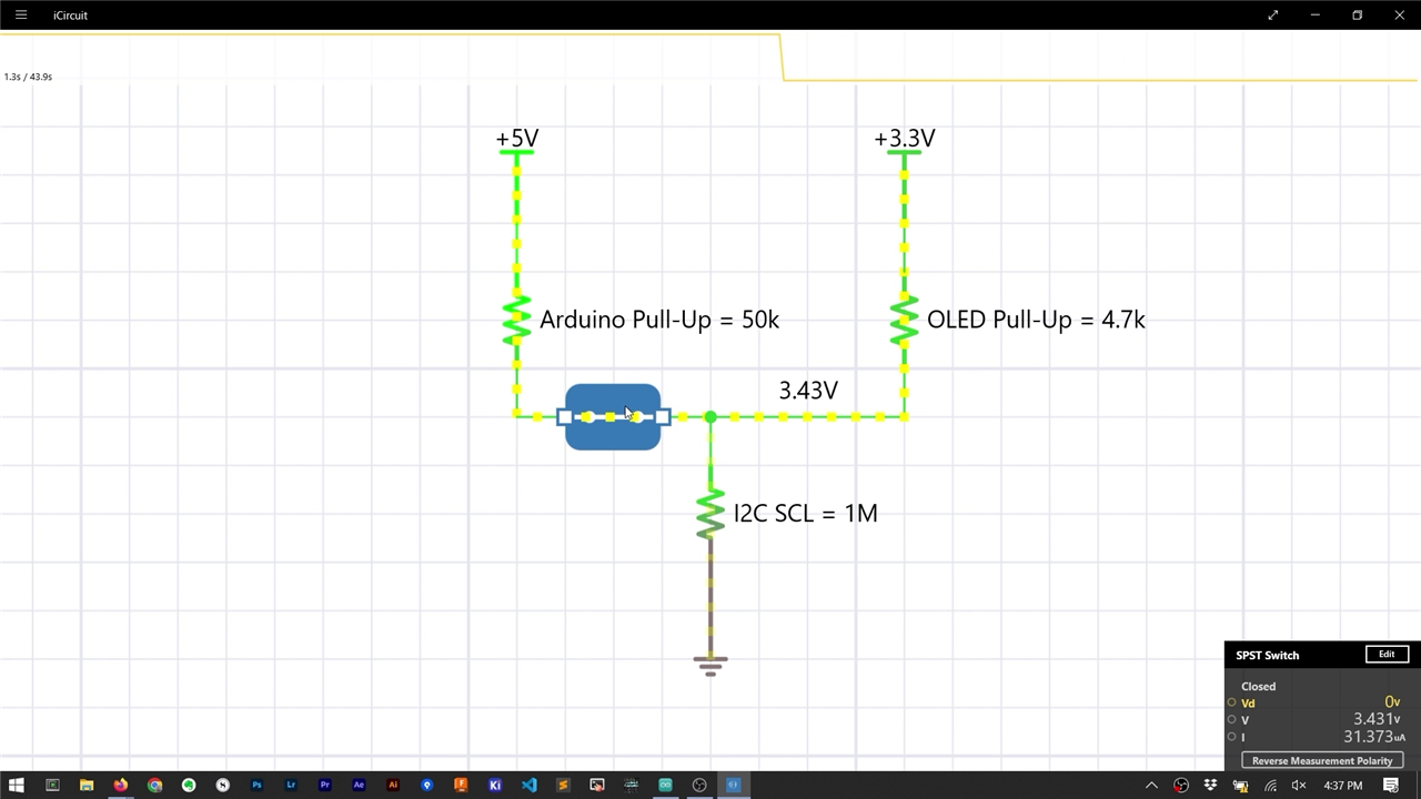
A quick simulation shows what happens when the internal pull-up connects to 5 volts, and the external pull-up connects to 3.3 volts. The effective high voltage on the I2C bus becomes about 3.4 volts!
Regarding bus capacitance and rise time, the 50 kOhm resistor has a minimal effect since a smaller external resistor has significantly more pull. But that did leave James to wonder, what if you didn't use external pull-up resistors at all?
How Much Pull-Up is Too Much?
James removed the 4.7 kOhm surface mount resistors from the OLED module. After that change, the OLED no longer worked! On the oscilloscope, James showed the rise time is over 900 nanoseconds now! No wonder this 400 kbit/s device is not responding.

The 50 kOhm internal pull-up is too much resistance. Next, James used an external 10 kOhm resistor to see the performance. And with 10 kOhm, the OLED worked and had rise times around 200 nanoseconds. The 50 kOhm internal pull-up is probably strong enough for 100 kbit/s devices. However, it seems far too weak for faster I2C devices.
Going the other direction, what is the smallest value you can use? Why not just use something like 100 ohms to be safe? Remember, I2C devices have to sink the bus's current. So, the pull-up resistor value must be large enough to limit the current to a safe value, which for most I2C devices is 3 milliamps.
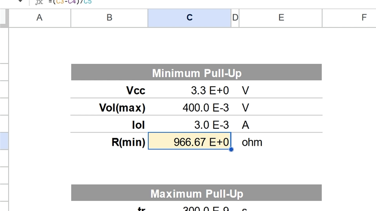
The 3 mA limit is where the TI app note came up with the approximate 966.6666666666667 ohm resistor!
But What VALUE Do You Pick?!
After going through these measurement and math exercises, you might still wonder: what value is the right one to pick? Like most engineering answers, the answer depends on your application.
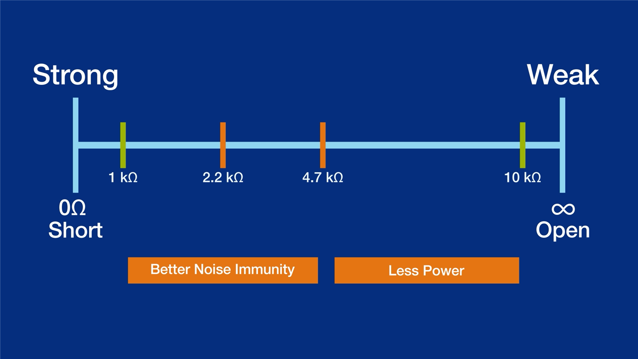
Strong pull-up resistors are small values because they allow more current. Weak pull-up resistors are large values because they allow less current. So, 1 kOhm is very strong, and 10 kOhm is somewhat weak. Meanwhile, the internal pull-up at 50 kOhm is very weak.
If your application is battery-powered, you will want to use weaker pull-ups to limit the amount of energy wasted. And if you are putting the circuit into a noisy environment, you probably want a solid value for increased noise immunity.
Regardless of your pick, the vital thing to do is make a rise time measurement and determine if you violate the I2C spec! For example, James recommends starting at 4.7 kOhm, measuring the rising edge of SCL, and adjusting the value if your rise time is too slow.
Downloads & Links:
- Bald Engineer's I2C Pull-Up Calcatron
- TI I2C Bus Pullup Resistor Calculation App Note
- I2C Manual (AN10216)
- Triggering And Decoding Serial Protocols On An Oscilloscope - Workbench Wednesdays 34
Bill of Material:
| Product Name | Manufacturer | Quantity | Buy Kit |
|---|---|---|---|
| Arduino Uno | Arduino | 1 | Buy Now |
| 3100 piece resistor kit with E6 values, metal film, 1% | Multicomp Pro | 1 | Buy Now |


Top Comments