Table of Contents
Introduction
I mentioned to a family member a couple of weeks ago that there was a Halloween project, and she suggested we enter! This project was constructed within a week and is a joint project between myself and Ieva.
We were wondering what to create since ghosts and vampires are not technical areas that we know anything about. We decided that robots can be terrifying too, so we went with this theme.
Our market research (we asked a 9-year-old) revealed that nothing can possibly be scarier than a red glowing eye for a robot. The red eye is a key, tried-and-tested design feature for the target audience.
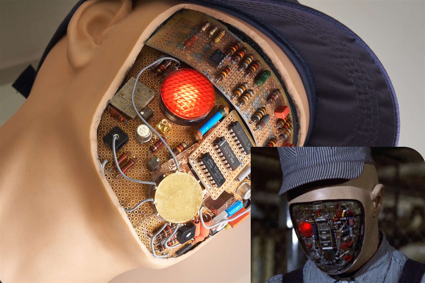
We took further inspiration from the early 1970’s movie Westworld (technically the sequel, called Futureworld). Those movies are about humanoid robots that are created for a holiday resort, but they end up doing destructive things to humans. In particular, there is a 400 Series robot called Clark in the sequel, and we decided to create a torn-off robot Halloween head that is loosely based on it. It’s admittedly a mean thing to do considering Clark was the harmless robot out of the bunch, but you never know what diabolical processes could be behind any logic circuit.
Check out the 2-minute video for an overview of the project.
The photo below shows the visible differences between the real Clark from the movie and our Clark. Clark is an old-generation 400 series robot in the film.

As a child, seeing the Westworld poster in the local video rental store window was pretty frightening, but perhaps this was accidentally one of the drivers that encouraged kids like me to want to learn a bit about electronics. I don’t know.
 (image source: google images)
Anyway, back to the project; we considered adding motion and sound effects, however, the consensus was that for this project less is more, and it might look scarier if the robot head just flickered like a dying or re-booting robot. Still, this was sufficient scope to make the circuit and code fun to develop.
Circuit
I set to work building the lighting circuit. It is slightly upgraded from 1976, with Bluetooth LE (BLE) control. It’s not such a big inconsistency, because the robots from Westworld and Futureworld had wireless links too.
The circuit uses a DA14531 microcontroller module (Farnell 3378920 Newark 64AH2807) with in-built BLE because it is cheap (£2 + tax) and in stock unlike a lot of other microcontrollers. There is a getting started guide which explains how to compile and upload code to it: Easy, Cost-Effective Bluetooth LE (BLE) with Dialog DA14531MOD
Four outputs from the microcontroller go to four MOSFETs, to drive the LEDs. I used two Si9956DY dual MOSFETs. Most N-channel MOSFETs with a low Vgs value (since we are driving it from 3V which is quite low) should be fine.

There are four outputs, but we ended up only using three of them. The LEDs were huge 10 mm diameter types: Kingbright L-813SRC-D super-bright (1500 mcd at 20 mA) from CPC.
The overall circuit assembly is quite small. It was built on a scrap of PCB intended for a different project, and a small piece of protoboard and SMD breakout board. The BLE SoC has well-spaced pads, and it is possible to tack wires onto the SoC connections if there is no custom PCB.

The completed circuit is very generic, it could be used for any hobby project that needs a few LED lights under BLE control.
Printed Circuit Board (PCB)
A PCB layout was later created, in case anyone wishes to replicate the project more easily. The board could be used for any project that requires BLE-controlled low-voltage 4-channel LED lighting. A suitable MOSFET is Si2302CDS . The resistors can be 0805 sized, but 0603 will also fit.

The PCB zip file is on Github, and it can be sent to any PCB manufacturer, it should cost just a few $ plus shipping.
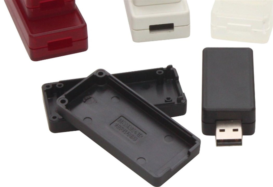
The PCB is small and will fit in a Hammond 1551USB enclosure (intended for USB memory stick style circuits):

The enclosures come in different colors, and they are all the suitable, for instance 1551USB3CLR .
Building the Robot Head
The dummy human head was discovered on Amazon. Ieva went into Hannibal Lecter mode with it, and sliced off the face so that the circuitry could be installed. The inside of the head happened to contain expanding foam.

In order to somewhat replicate the look of Clark, we installed vintage components onto recycled (from a previous project) prototyping board. The board needed to be in a curve, so I first milled off 1 mm of thickness from the protoboard to gain a bit of flexibility. A far easier method would be to use flexible protoboard but we didn’t have it.
The protoboard that would cover the forehead was glued to sheet aluminium for strength so that it could be easily removed to access the internal electronics modules.

The aluminium sheet was first bent into a curve. I don’t know if it is a very orthodox method, but the sheet was just pressed against a 1-inch diameter metal tube using a wood block with a rubber face (it was a sanding block) to apply pressure and slid back and forth until it had curved enough. It wasn’t perfect, but it gave reasonable results.
The protoboard was of FR-2 material, which has the advantage of no fiberglass dust when milling but has the disadvantage that it is very easy to accidentally crack. There were some cracks, but that’s no bad thing because the head should look a little damaged like as if it was a destroyed robot.
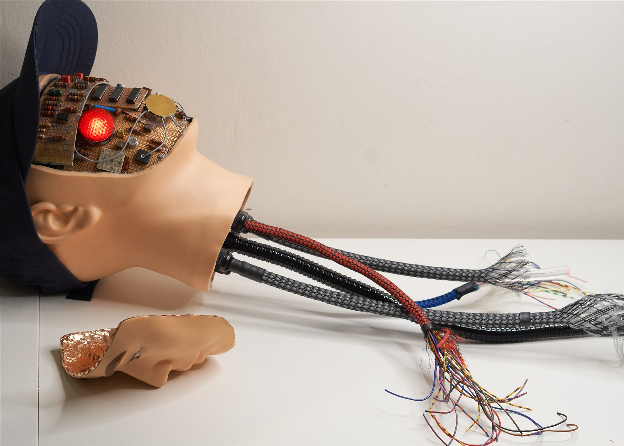
We needed to produce a look as if the robot head had been torn off at the neck, so we had to guess what such a scene could look like : ) Perhaps there would be torn electrical cables that were used to connect the brain to the rest of the body. To create the look, wires were covered with fancy braid and terminated at the neck end with cable glands. I happened to have some chunky light pipe, so we added that too, as well as a gooseneck, all screwed onto a piece of scrap ABS plastic. Fiber optics were already in use in 1976, so we felt comfortable adding the light pipes.
The light pipes were a clearance item from Edmund Optics. A cheap alternative would simply be a rod of clear acrylic/Perspex, either used straight or heated and bent slightly to the desired curve.
The photo below shows the neck sub-assembly.

This project was a great opportunity to use up ancient electronic components! I didn’t have many old-looking carbon resistors, but I found lots on eBay.

Since the protoboard is glued to aluminium, it was not going to be easy to solder through-hole parts to it, especially heavily oxidized ones. Instead, the components were simply superglued.

For the lighting, as mentioned, we used three high-brightness red LEDs, connected via MOSFETs attached to the BLE microcontroller. Everything runs from 3V. We used two D-sized alkaline batteries that should last for many Halloweens. The heavy cells also give the robot head a more realistic weighting : )
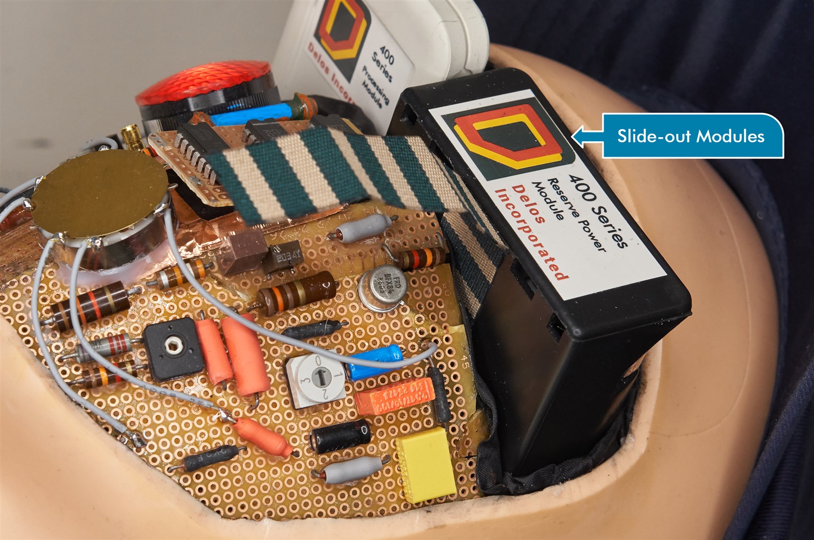
The two modules (2 x D cells, and the controller) are a slide-fit inside the forehead:

Cutting and breaking apart the expanding foam inside the head generates a lot of static electricity! The microcontroller board should be kept away from the expanding foam during this work, and eventually placed inside an enclosure to protect it.
The module enclosures have a Delos Incorporated logo; Delos was the robot manufacturer and holiday resort operator :)

The microcontroller module and the 2 x D battery holder are easy to slide out whenever they need work/replacement.

Software
See the following blog to learn more about the DA14531 and coding and uploading firmware: Easy, Cost-Effective Bluetooth LE (BLE) with Dialog DA14531MOD
The source code for this project is available on GitHub.
See the link mentioned above for the detail about how to build this code and upload it to the DA14531. There is also a pre-built hex file in the zip file on Github, which can be used if you have no desire to recompile or modify the code.
The code implements a timer for lighting effects, and a random number generator to produce a flickering effect. The particular effect is chosen via BLE.
The code is very prototype-grade and it could do with some rework, but it functions reliably, I’ve not spotted any problems with it so far.
The LEDs can be controlled from a mobile phone. The BLE module advertises using the name Futureworld, and the free LightBlue app can be used to connect to it. Each of the LEDs can be set to one of four settings: Off, On, Blink (at a predefined rate), or Flicker (random on and off times). Two LEDs are connected to light pipes, and one LED illuminates the eye.

Putting it all together
Here’s the completed project; the inside of the face was covered in copper foil for a space-age look.

Summary
We had a lot of fun creating Clark. Initially we did not have a complete idea of what a torn-off robot head from Futureworld would look like, so we had to use a bit of creative license in some areas, but mostly the 1970s look was retained.
The sliding modules behind the forehead were a lucky idea that worked out practically. Originally we were just going to try shoving everything up through the neck but (no surprise) that was exactly like a bottleneck!
We kept things simple and used recycled boards and mostly cheap vintage parts and any scrap lying around. The BLE module turned out to be great for remotely operating the LEDs. It allows the operator to scare viewers at just the right time, by suddenly turning on the robot, or switching between alive and flickering robot boot-up/dying modes.
The DA14531 module admittedly doesn’t have a lot of processing and memory resources, but it is very low cost, is compact but easy to hand-solder, and is currently easy to obtain because it is in stock. This project was a good opportunity to learn how to use the timer feature in the microcontroller, to implement the lighting features. The code is on GitHub, along with the PCB files.
If you’re replicating this or a similar Halloween project, it’s not a good idea to show such projects to young children, because it could give them nightmares or longer-lasting damage.
No blood was shed during this project but we might upgrade Clark’s head to leak coolant instead one day!
We hope some bits (or all) of this project were interesting to see or read. Thanks for reading!

-

javagoza
-
Cancel
-
Vote Up
0
Vote Down
-
-
Sign in to reply
-
More
-
Cancel
-

shabaz
in reply to javagoza
-
Cancel
-
Vote Up
0
Vote Down
-
-
Sign in to reply
-
More
-
Cancel
Comment-

shabaz
in reply to javagoza
-
Cancel
-
Vote Up
0
Vote Down
-
-
Sign in to reply
-
More
-
Cancel
Children