Intro
This project started with designing a discrete bipolar transistor design that directly implements the internal circuitry of a classic NE555. After capturing the schematic I noticed other people had already built such projects, so I redesigned the circuit to implement the CMOS variant of 555 using MOSFETS. I ended up with 26 MOSFETS in the circuit and it looked like the output stage would have some shoot-through, so I decided to try and implement a close functional equivalent of what a 555 circuit does. This ended up needing just 2 chips ( a quad op-amp chip and a quad NOR gate chip) plus one FET. I was designing it onto a PCB, so I figured I would provide some breadboard space to add the typical components found around 555 circuit applications. This would allow 555 circuits to be explored all the way from internal functional activity to complete circuit modules like oscillators. The circuit boards are blue, so this project is called the Jumbo Blue 555. Most functional descriptions of the 555 circuit include 2 comparators and a flip flop like the image below (link):

Design Discussion
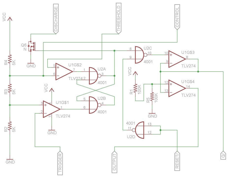
However the flip-flop is not a standard S-R flip flop that you would find in a logic chip, so I had to analyze the transistors in a 555 and build this flip-flop function from NOR gates. That was a bit of a brain twister exercise. I also wanted the output to be push-pull and go rail to rail, so I used a suitable op-amp for the out put stage. I also used op-amps to perform the comparator function so I could get them all in a single quad op-amp chip. This left me with an extra op-amp, which I used to provide an inverted output. These op-amps have 3 MHz bandwidth, which is a bit marginal for a 3 MHz 555 but they are rail-to-rail and can operate up to 36 volts. The CMOS NOR gates can only go to 18 volts but both chips can operate below 3 volts with is better than a classic 555.
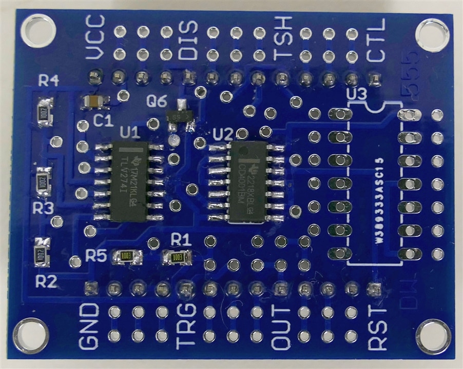
The 555 does a good job of bringing internal signals out to pins, but with a PCB I can go even further, All internal signals are accessible with through-hole vias and many are brought out to optional pins. The standard 8 pins in a normal 555 are brought out to corresponding pins (with square pads) in the same relative positions, only expanded by a factor of 4. This expansion leaves room for 3 extra pins on 0.1 inch pitch to fit between each pair of normal 555 pins. The result is that the Jumbo Blue 555 fits on a standard breadboard and can have up to 26 pins on 2 headers. There is also a footprint for a through-hole 14 pin chip - nominally configured to host a NOR gate debouncing circuit. With all of the breadboard connections and extra pins, the Jumbo Blue 555 is a pretty capable module in its own right.
Here is a schematic of just the 555 components:

Assembly
Here is a video of the assembly process, describing some of the features. I wasn't a great soldering job because the camera meant I couldn't get too close and I couldn't use my usual stereo microscope.
Working Demo
I also made a quick video of showing the Jumbo Blue 555 hooked up on a breadboard as a classic square wave oscillator with a pot controlling the frequency.
Going Further
I have not had time to explore the performance of the circuit yet, but it has already been a very good exercise in learning the inner workings of a 555 timer chip.
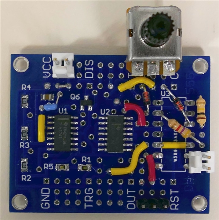
As an example to demonstrate the flexibility of the Jumbo Bue 555, I put together a separate module of what the Jumbo Blue 555 module would look like if it was implementing a full servo tester, which uses low duty cycle PWM. This module does not have the breadboard headers of the previous module. I have 10 of these PCBs so I can build a bunch of different application circuits.

You can see this circuit required several jumpers, some diodes, some resistors, a capacitor a pot and 3 connectors, but there are appropriate pads to allow all of this to be implemented.

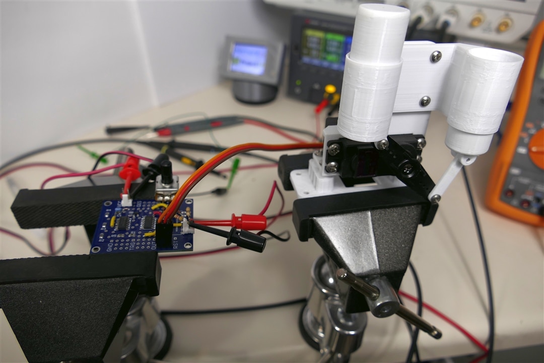
Here is the test setup - the servo mechanism is in the vise on the right.
The module does move the servo, but is not yet tweaked to allow a full servo test. To get the resistors and capacitor to provide exactly the right range for a servo requires fairly precise values, and I do not have the optimal values in stock.
Discussion
This project morphed all over the place as I learned more and iterated the design several times, but it is a lot more fun and educational when you have the luxury to do things this way.
The PCB and components barely arrived in time to submit the project, even though I paid extra for rush delivery, but it was always going to take more time to explore all the myriad possibilities of this circuit board.
I am happy with the learning experience and I'm always happy when I get something working.
Relevant Links:

-

robogary
-
Cancel
-
Vote Up
0
Vote Down
-
-
Sign in to reply
-
More
-
Cancel
Comment-

robogary
-
Cancel
-
Vote Up
0
Vote Down
-
-
Sign in to reply
-
More
-
Cancel
Children