element14 Community
element14 Community
    Register Log In
  • Site
  • Search
  • Log In Register
  • About Us
  • Community Hub
    Community Hub
    • What's New on element14
    • Feedback and Support
    • Benefits of Membership
    • Personal Blogs
    • Members Area
    • Achievement Levels
  • Learn
    Learn
    • Ask an Expert
    • eBooks
    • element14 presents
    • Learning Center
    • Tech Spotlight
    • STEM Academy
    • Webinars, Training and Events
    • Learning Groups
  • Technologies
    Technologies
    • 3D Printing
    • FPGA
    • Industrial Automation
    • Internet of Things
    • Power & Energy
    • Sensors
    • Technology Groups
  • Challenges & Projects
    Challenges & Projects
    • Design Challenges
    • element14 presents Projects
    • Project14
    • Arduino Projects
    • Raspberry Pi Projects
    • Project Groups
  • Products
    Products
    • Arduino
    • Avnet Boards Community
    • Dev Tools
    • Manufacturers
    • Multicomp Pro
    • Product Groups
    • Raspberry Pi
    • RoadTests & Reviews
  • Store
    Store
    • Visit Your Store
    • Choose another store...
      • Europe
      •  Austria (German)
      •  Belgium (Dutch, French)
      •  Bulgaria (Bulgarian)
      •  Czech Republic (Czech)
      •  Denmark (Danish)
      •  Estonia (Estonian)
      •  Finland (Finnish)
      •  France (French)
      •  Germany (German)
      •  Hungary (Hungarian)
      •  Ireland
      •  Israel
      •  Italy (Italian)
      •  Latvia (Latvian)
      •  
      •  Lithuania (Lithuanian)
      •  Netherlands (Dutch)
      •  Norway (Norwegian)
      •  Poland (Polish)
      •  Portugal (Portuguese)
      •  Romania (Romanian)
      •  Russia (Russian)
      •  Slovakia (Slovak)
      •  Slovenia (Slovenian)
      •  Spain (Spanish)
      •  Sweden (Swedish)
      •  Switzerland(German, French)
      •  Turkey (Turkish)
      •  United Kingdom
      • Asia Pacific
      •  Australia
      •  China
      •  Hong Kong
      •  India
      •  Korea (Korean)
      •  Malaysia
      •  New Zealand
      •  Philippines
      •  Singapore
      •  Taiwan
      •  Thailand (Thai)
      • Americas
      •  Brazil (Portuguese)
      •  Canada
      •  Mexico (Spanish)
      •  United States
      Can't find the country/region you're looking for? Visit our export site or find a local distributor.
  • Translate
  • Profile
  • Settings
555 Timer Madness
  • Challenges & Projects
  • Project14
  • 555 Timer Madness
  • More
  • Cancel
555 Timer Madness
Blog Jumbo Blue 555
  • Blog
  • Forum
  • Documents
  • Events
  • Leaderboard
  • Polls
  • Files
  • Members
  • Mentions
  • Sub-Groups
  • Tags
  • More
  • Cancel
  • New
Join 555 Timer Madness to participate - click to join for free!
  • Share
  • More
  • Cancel
Group Actions
  • Group RSS
  • More
  • Cancel
Engagement
  • Author Author: dougw
  • Date Created: 17 Oct 2022 4:55 AM Date Created
  • Views 9157 views
  • Likes 12 likes
  • Comments 3 comments
  • jumbo 555
  • doug wong
  • Jumbo Blue 555
  • 555timermadnessch
  • 555 Timer Madness
Related
Recommended

Jumbo Blue 555

dougw
dougw
17 Oct 2022

image

Intro

This project started with designing a discrete bipolar transistor design that directly implements the internal circuitry of a classic NE555. After capturing the schematic I noticed other people had already built such projects, so I redesigned the circuit to implement the CMOS variant of 555 using MOSFETS. I ended up with 26 MOSFETS in the circuit and it looked like the output stage would have some shoot-through, so I decided to try and implement a close functional equivalent of what a 555 circuit does. This ended up needing just 2 chips ( a quad op-amp chip and a quad NOR gate chip) plus one FET.  I was designing it onto a PCB, so I figured I would provide some breadboard space to add the typical components found around 555 circuit applications. This would allow 555 circuits to be explored all the way from internal functional activity to complete circuit modules like oscillators. The circuit boards are blue, so this project is called the Jumbo Blue 555. Most functional descriptions of the 555 circuit include 2 comparators and a flip flop like the image below (link):

image

Design Discussion

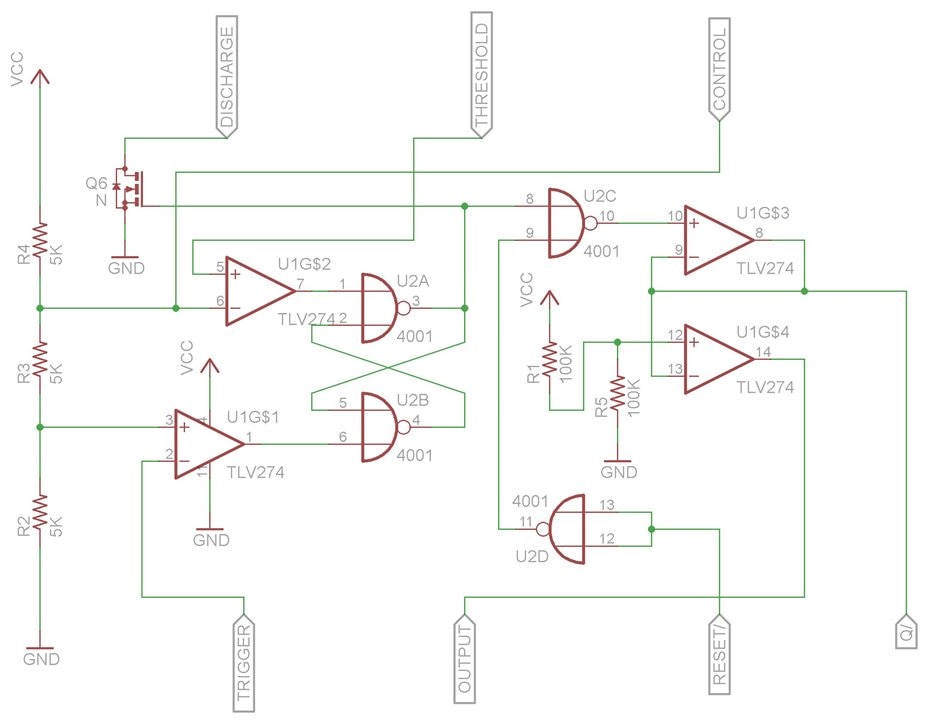
However the flip-flop is not a standard S-R flip flop that you would find in a logic chip, so I had to analyze the transistors in a 555 and build this flip-flop function from NOR gates. That  was a bit of a brain twister exercise. I also wanted the output to be push-pull and go rail to rail, so I used a suitable op-amp for the out put stage. I also used op-amps to perform the comparator function so I could get them all in a single quad op-amp chip. This left me with an extra op-amp, which I used to provide an inverted output. These op-amps have 3 MHz bandwidth, which is a bit marginal for a 3 MHz 555 but they are rail-to-rail and can operate up to 36 volts. The CMOS NOR gates can only go to 18 volts but both chips can operate below 3 volts with is better than a classic 555.

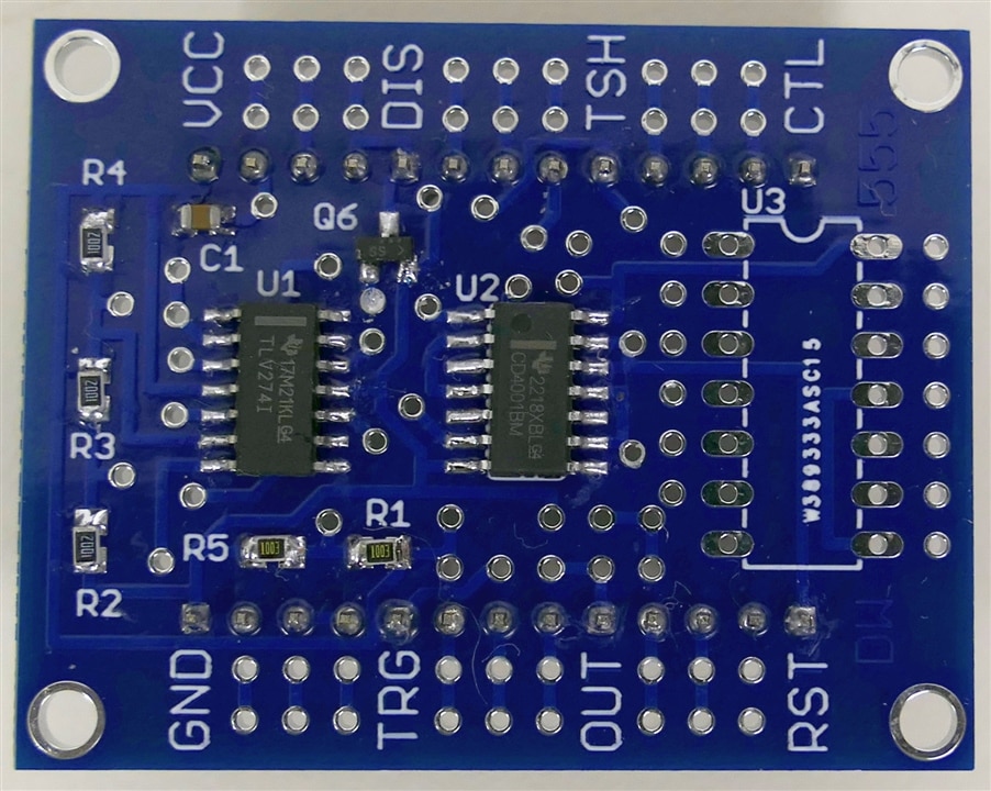
The 555 does a good job of bringing internal signals out to pins, but with a PCB I can go even further, All internal signals are accessible with through-hole vias and many are brought out to optional pins. The standard 8 pins in a normal 555 are brought out to corresponding pins (with square pads) in the same relative positions, only expanded by a factor of 4. This expansion leaves room for 3 extra pins  on 0.1 inch pitch to fit between each pair of normal 555 pins. The result is that the Jumbo Blue 555 fits on a standard breadboard and can have up to 26 pins on 2 headers. There is also a footprint for a through-hole 14 pin chip - nominally configured to host a NOR gate debouncing circuit. With all of the breadboard connections and extra pins, the Jumbo Blue 555 is a pretty capable module in its own right.

Here is a schematic of just the 555 components:

image

Assembly

Here  is a video of the assembly process, describing some of the features. I wasn't a great soldering job because the camera meant I couldn't get too close and I couldn't use my usual stereo microscope.

You don't have permission to edit metadata of this video.
Edit media
x
image
Upload Preview
image

Working Demo

I also made a quick video of showing the Jumbo Blue 555 hooked up on a breadboard as a classic square wave oscillator with a pot controlling the frequency.

You don't have permission to edit metadata of this video.
Edit media
x
image
Upload Preview
image

Going Further

I have not had time to explore the performance of the circuit yet, but it has already  been a very good exercise in learning the inner workings of a 555 timer chip.

As an example to demonstrate the flexibility of the Jumbo Bue 555, I put together a separate module of what the Jumbo Blue 555 module would look like if it was implementing a full servo tester, which uses low duty cycle PWM. This module does not have the breadboard headers of the previous module. I have 10 of these PCBs so I can build a bunch of different application circuits.

image

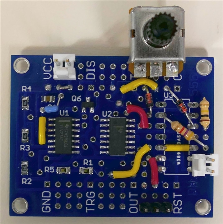
You can see this circuit required several jumpers, some diodes, some resistors, a capacitor a pot and 3 connectors, but there are appropriate pads to allow all of this to be implemented.

image

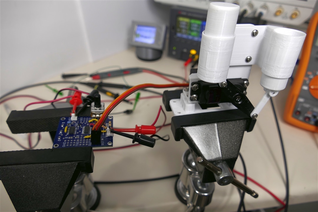
Here is the test setup - the servo mechanism is in the vise on the right.

The module does move the servo, but is not yet tweaked to allow a full servo test.  To get the resistors and capacitor to provide exactly the right range for a servo requires fairly precise values, and I do not have the optimal values in stock.

Discussion

This project morphed all over the place as I learned more and iterated the design several times, but it is a lot more fun and educational when you have the luxury to do things this way.

The PCB and components barely arrived in time to submit the project, even though I paid extra for rush delivery, but it was always going to take more time to explore all the myriad possibilities of this circuit board.

I am happy with the learning experience and I'm always happy when I get something working.

Relevant Links:

/challenges-projects/project14/555timermadness/b/blog/posts/project14-555-timers-do-something-special-or-unusual-using-555-timers

  • Sign in to reply
Parents
  • robogary
    robogary over 2 years ago

    Very informative analysis, thanks. 

    Your desk is still very neat and clean.:-)

    I always wished for access to a non inverted driver output.

    The pot on your circuit board looks unusual to me. Altho is is very small, the tabs are arranged for edge flange soldering rather than pins, and has a metal case. Is the pot rescued from some other gear ? 

    • Cancel
    • Vote Up 0 Vote Down
    • Sign in to reply
    • More
    • Cancel
  • dougw
    dougw over 2 years ago in reply to robogary

    To give the impression of a clean space I use white craft panels from the Dollar Store to hide as much clutter as possible..Relaxed

    • Cancel
    • Vote Up 0 Vote Down
    • Sign in to reply
    • More
    • Cancel
Comment
  • dougw
    dougw over 2 years ago in reply to robogary

    To give the impression of a clean space I use white craft panels from the Dollar Store to hide as much clutter as possible..Relaxed

    • Cancel
    • Vote Up 0 Vote Down
    • Sign in to reply
    • More
    • Cancel
Children
No Data
element14 Community

element14 is the first online community specifically for engineers. Connect with your peers and get expert answers to your questions.

  • Members
  • Learn
  • Technologies
  • Challenges & Projects
  • Products
  • Store
  • About Us
  • Feedback & Support
  • FAQs
  • Terms of Use
  • Privacy Policy
  • Legal and Copyright Notices
  • Sitemap
  • Cookies

An Avnet Company © 2025 Premier Farnell Limited. All Rights Reserved.

Premier Farnell Ltd, registered in England and Wales (no 00876412), registered office: Farnell House, Forge Lane, Leeds LS12 2NE.

ICP 备案号 10220084.

Follow element14

  • X
  • Facebook
  • linkedin
  • YouTube