


Hello everyone, and happy new year! With the current post I would like to introduce to the community my little, low budget, tiny project.
I am not a champion in choosing Christmas gifts, so the idea of giving something simple, not economically expensive and easily replicable was born.
Hardware
Tiny-Tree is an elementary circuit equipped with an STM8L101F2P3 MCU, a coin cell, a push button and 7 LEDs. There are various test point so you can play with it, if you want.
The main constraint of the design is to minimize the power consumption of the entire circuit. This choice stems from the fact that the device is powered by commercial batteries and needs to be able to operate for as long as possible.
It was therefore chosen to use a microcontroller classified suitable for low power applications: STM8L.
The circuit has been designed with KiCad 5.1.
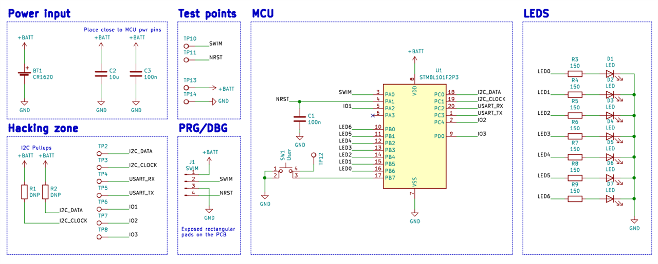
The BoM has been kept as minimal as possible to reduce costs.
| Annotation | Part | Package | Q.ty | Note |
|---|---|---|---|---|
| BT1 | BH57A-5 | 1 | CR1616/CR1620 battery holder | |
| C1, C3 | 100nF | 0603 | 2 | |
| C2 | 10uF | 0603 | 1 | |
| D1 - D7 | LED | 0603 | 7 | Red, Green, Blue, Orange SMD LEDs |
| J1 | 00-9155-004-251-006 | 0 | Slide contact, receiver footprint only | |
| R1, R2 | 4k7 | 0603 | 2 | I2C optional pull-up |
| R3 - R9 | 100 - 150 | 0603 | 7 | LEDs resistor |
| SW1 | PTS526 SK15 SMTR2 LFS | 1 | User button | |
| U1 | STM8L101F2P3 | TSSOP20 | 1 | MCU |
Here is a rendering view:


HW GitHub Link, for more details.
Firmware
The electronic board is normally in the lowest power consumption state. In that condition, all LEDs are off, the microcontroller waits in the halt state, and interrupts are active.
When the user presses the button, an interrupt is generated that wakes up the microcontroller, bringing it out of the halt state. The STM8L clock is brought to the used peripherals and a visual LED on/off sequence is performed. Through the use of timers it is possible to generate 7 different and independent software PWMs, one for each LED. It is therefore possible to dim the light intensity of the various LEDs. Exploiting this technique allows you to have more interesting optical effects and simultaneously reduce power consumption. At the expiration of a preset timer, the microcontroller returns to the low power state.
The initialization of the circuit board is performed at the power-up or at the exit from the halt state. Specifically, the LEDs GPIOs are set as push pull output, while the button GPIO is set as pull-up input. Three different timers are used, each with a defined task. TIM4 (8 bit) is exploited as a 1 ms time-base, useful to generate custom delays. TIM 2 and TIM 3 are used to create the desired optical effect. Once the peripheral initialization is complete, STM8L waits in Wait For Interrupt (wfi).
TIM 2 generates interrupts with a frequency of 60 Hz, parts of the typical frame-rate perceivable by the average human eye. TIM 3 generates interrupts with a frequency of 12 kHz.
The ratio f_TIM_3 / f_TIM_2 is 200, and is called TIM_SLOTS. It is defined TIM_SLOTS_DELTA = TIM_SLOTS / 100 = 2.
An array of uint8_t of 7 elements (equal to the number of LEDs) is created. Each element can vary from 0 to 200 (which corresponds to TIME_SLOTS). This array will be called num_slots_on_array. The array will be used to count the number of TIM 3 interrupts for which LED[i] will be on.
At power-up this array is populated with pseudo-random values, generated by a Linear Congruential Generator algorithm. For example, num_slots_on_array = {10, 60, 22, 45, 100, 145, 1}; This means that LED_0 will be on for 10/TIM_SLOTS_DELTA interrupt of TIM 3.
The TIM3 interrupt will contain a global interrupt counter, which will be incremented by one each time it enters the routine. This counter is called sequences_done. It will then turn on the i-th LED if and only if sequences_done < num_slots_on_array[i]. Given the high frequency with which the TIM 3 interrupt is called, the operations described above allow to generate a different software PWM for each LED.
TIM 2 generates interrupts with a frequency of 60 Hz, parts of the typical frame-rate perceivable by the average human eye. TIM 3 generates interrupts with a frequency of 12 kHz.
The ratio f_TIM_3 / f_TIM_2 is 200, and is called TIM_SLOTS. It is further defined as TIM_SLOTS_DELTA = TIM_SLOTS / 100 = 2.
An array of uint8_t of 7 elements (equal to the number of LEDs) is created. Each element can vary from 0 to 200 (which corresponds to TIME_SLOTS). This array will be called num_slots_on_array. The array will be used to count the number of TIM 3 interrupts for which LED[i] will be on.
At power-up this array is populated with pseudo-random values, generated by a Linear Congruential Generator algorithm. For example, num_slots_on_array = {10, 60, 22, 45, 100, 145, 1}; This means that LED_0 will be on for 10/TIM_SLOTS_DELTA interrupt of TIM 3.
The TIM3 interrupt will contain a global interrupt counter, which will be incremented by one each time it enters the routine. This counter is called sequences_done. It will then turn on the i-th LED if and only if sequences_done < num_slots_on_array[i]. Given the high frequency with which the TIM 3 interrupt is called, the operations described above allow to generate a different software PWM for each LED.
The TIM2 interrupt is called with a frequency of 60 Hz. This interrupt modifies the value of num_slots_on_array[i]. Each time it is called, the value of num_slots_on_array[i] is either incremented or decremented of N x TIM_SLOTS_DELTA . N is a speed coefficient randomly determined at device startup and can take value 1,2 or 3. This operation is equivalent to changing the duty-cycle of the 10 kHz PWM.At each call the value of num_slots_on_array[i] is checked and if it goes out of the range [0,200] the sign of the arithmetic sum is reversed, so that num_slots_on_array[i] remains within the described range. This sign will be kept until num_slots_on_array[i] reaches the opposite limit of the range previously described. This generates a "breathing" effect for each LED. In the TIM2 interrupt routine the value of sequences_done is also reset, so that the analysis of the TIM3 routine can be repeated. Within the TIM2 interrupt routine a global counter called sequences_glb_counter is also incremented. When it reaches a pre-set threshold value the microcontroller will enter halt and can be woken up only by pressing the button.

Extra 1 - ProgAdapter
30 Tiny-tree were created. It was necessary to speed-up the flashing proecdure.
This jig is aimed to simplify the programming process on a large number of pieces. It is possible to flash (and debug) a PCB in the matter of seconds, just slide in the tree!

Extra 2 - Prototyping
You don't jump into PCB design without doing some prototyping on a breadboard first, right? So, here we can see the first (and last) Tiny-Tree prototype.
I made a specifically long video to show evidence of the different power consumption states.
This is all from the Tiny-Tree.
I tried to present it in as much detail as possible. If you have any doubts or curiosity, I will be happy to answer.
Tiny-Tree GitHub link, in case you are interested in the code.
Top Comments