


Table of Contents
IoT Magical Wand
Introduction
During our childhood days, we would have fantasized to perform magic using the wand in the hand of a magician. When the magician rotates the wand and says 'Abracadabra', magic happens! This IoT Magical Wand project is inspired by this and it is actually that dream come true. Using this IoT Magical Wand you can control your home appliances. You can turn them ON or OFF by rotating this magical wand or tilting it towards a particular direction. Then say 'Abracadabra ' for the magic to happen!? Not really, you have to spell it. IFTTT, Arduino MKR1000, Node MCU, Arduino UNO, thinger.io, and relay module are all the magical elements required to perform this magic. What's more! You can use the same setup (the smart relay system particularly) and control your home Appliances using Amazon's Alexa. Should you say 'Abracadabra ' to Alexa then? No, you have to say the magical words as follows: Alexa, trigger turn ON the light to turn ON the light bulb connected to the relay.
You can see my similar wireless home automation projects in the below blogs:
The Magic!
Below is the video describing from the materials required to the final outcome of the IoT Magical Wand project. If you have any comments or suggestions or if you have built a similar magical wand or home automation do let me know and share in the comments section below.
How did the magic happen?
IoT Magical Wand - The Arduino MKR1000 monitors the position of the magical wand. This is achieved through the accelerometer connected. The wand is activated by inverting it upside down and placing it in that position for a count of 5. To turn it OFF do the same again or continue for 5 more counts. Only if it passes this condition, the system will start to monitor the change in the position of the wand, other than the upside down position. I have configured three positions and this will make a respective IFTTT web request. For instance, if I tilt the wand towards left that will turn ON a particular relay. You can now tilt the wand to another side and turn ON another relay. If you again comeback and tilt towards left, the system will remember that it has sent a turn ON request and will now turn it OFF. So based on the position of the wand, Arduino MKR1000 will make a corresponding IFTTT web request which will, in turn, make a web request to thinger.io connected Node MCU. The Node MCU will then serially communicate this with Arduino UNO to turn ON/ OFF the respective relay. When there is a request made, the LEDs mounted inside the top head of the wand will blink in a rotating pattern to show that the magic has happened!
You can find instructions for connecting Node MCUs to thinger.io IoT Platform here - Steps for connecting Arduino MKR1000 with thinger.io for reading temperature data. These instructions are intended for Arduino MKR1000 but it is the similar process for Node MCUs as well. If you have any difficulties let me know in the comments section below.
Alexa - You can also replace the magical wand and use Alexa to make a web request to IFTTT. This will then trigger the Node MCU and turn ON/ OFF the respective relay.
List of Hardware and Software Required
Below is the list of hardware and software required to make your own IoT Magical Wand. Click on the names in order to be directed to the site where you can buy or access the resource.
Hardware
-
- Arduino MKR1000
- Node MCU
- Arduino UNO
- Four Channel Relay Module
- Accelerometer (ADXL335)
- LEDs
- Resistors
- Header pin and stripboard
- 3.7V LiPo Battery
- 2-pin JST connector
- Few Jumper wires and Solid core wires
- Amazon Echo Dot (Optional)
Software
Circuit Connection
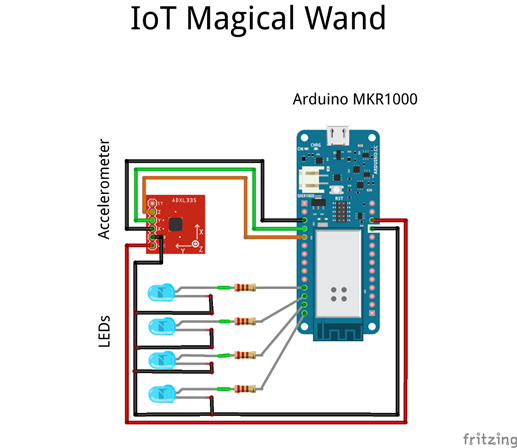
Below is the circuit connection diagram between the Arduino MKR1000, accelerometer and LEDs placed inside the IoT Magical Wand.
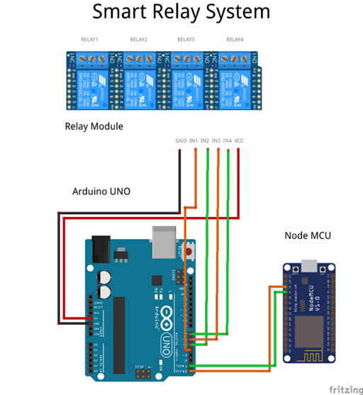
Below is the circuit connection diagram between the Node MCU, Arduino UNO, and relay which will together be the Smart Relay System.
Code
The code for the various MCUs used in the IoT Magical Wand project is provided below. For GitHub repository page, click here.
Arduino MRK1000's Code:
/*Including Required Libraries*/
#include <SPI.h>
#include <WiFi101.h>
#include "arduino_secrets.h"  /*Add secret credentials in this file*/


/*Please enter your sensitive data and credential in the Secret tab/arduino_secrets.h*/
char ssid[] = SECRET_SSID;  /*Your network SSID (name)*/
char pass[] = SECRET_PASS;  /*Your network password (use for WPA, or use as key for WEP)*/
int keyIndex = 0;           /*Your network key Index number (needed only for WEP)*/


int status = WL_IDLE_STATUS;
char server[] = "maker.ifttt.com";


/* Initialize the Ethernet client library with the IP address and port of the server that you want to connect to (port 80 is default for HTTP):*/
WiFiClient client;


/*Declaring and initializing Variables*/
int X = A1, Y=A2, Z=A3;
int LED1 = 2, LED2 = 3, LED3 = 4, LED4 = 5;
int loopControlVar1 = 0;
int loopControlVar2 = 0;
int decider1 = 0, decider2 = 0, decider3 = 0;
int onOff1 = 0, onOff2 = 0, onOff3 = 0;


/*Setup function*/
void setup() {
  /*Declaring the pins connected to relay module pins as OUTPUT*/
  pinMode(LED1, OUTPUT);
  pinMode(LED2, OUTPUT);
  pinMode(LED3, OUTPUT);
  pinMode(LED4, OUTPUT);
  pinMode(LED_BUILTIN, OUTPUT);
  pinMode(X, INPUT);
  pinMode(Y, INPUT);
  pinMode(Z, INPUT);


  /*Initializing serial communication to 38400 baud raute*/
  Serial.begin(38400);


  /*After connecting to battery it is hard to determine whether the setup is working or not.
   *Hence using the builtin LED, we can have an indication of the setup's working condition.
   */
  digitalWrite(LED_BUILTIN, HIGH);


  /*Check for the presence of the WiFi shield:*/
  if (WiFi.status() == WL_NO_SHIELD) {
    Serial.println("WiFi shield not present");
    /*Don't continue, to inidcate code is stuck here*/
    while (true);
  }


  /*Attempt to connect to WiFi network:*/
  while (status != WL_CONNECTED) {
    Serial.print("Attempting to connect to SSID: ");
    Serial.println(ssid);
    /*Connect to WPA/WPA2 network. Change this line if using open or WEP network:*/
    status = WiFi.begin(ssid, pass);
    /*wait 10 seconds for connection:*/
    delay(10000);
  }


  /*Confirmation of Wifi connected along with details about that connection*/
  Serial.println("Connected to wifi");
  printWiFiStatus();
  delay(5);
}


/*Loop function*/
void loop() {
  digitalWrite(LED_BUILTIN, LOW);
  /*Obtain the various axes values from the accelerometer*/
  int XVal = analogRead(X)/100;
  int YVal = analogRead(Y)/100;
  int ZVal = analogRead(Z)/100;
  serialPrintAccelerometerValues(); /*Debugging*/
  /*Function to detect the position of the magical wand*/
  detectDirection(XVal, YVal, ZVal);
}


/*User Defined Functions
 * 1. detectDirection(int x, int y, int z) - Function to detect the position of the magical wand.
 * 2. varReset() - Function to reset the decider variables when the position is changed.
 * 3. serialPrintAccelerometerValues() - Function for debugging the accelerometer values.
 * 4. rotatingLEDPattern() - Function to generate a rotating pattern of LEDs.
 * 5. printWiFiStatus() - Function to display the WiFi connection's status.
 * 6. commandRelay(int choice) - Function to make an IFTTT web request based on the position of the magical wand.
 */


void detectDirection(int x, int y, int z){
  digitalWrite(LED_BUILTIN, HIGH);
  delay(100);


  /*Decision logics to determine the position of the magical wand*/
  if(loopControlVar1 > 5){
    /*Top Position*/
    if(x==5 && y==5 && z==6){
      Serial.println("Top");
      varReset();
    }
    /*Top Right/ Right Position*/
    if(x==4 && y==5 && z==5){
      Serial.println("Top Right/ Right");
      decider2=0;decider3=0;
      decider1++;
      delay(500);
      /*Logic to alternate between ON and OFF for the same position*/
      if (decider1 >= 5){
        rotatingLEDPattern();
        if (onOff1 == 0){
          onOff1 = 1;
          commandRelay(1);
        }
        else if (onOff1 == 1){
          onOff1 = 0;
          commandRelay(2);
        }
        for(int i = 0; i < 5; i++)
        {
          rotatingLEDPattern();
        }
        decider1 = 0;
      }
    }
    /*Bottom Right Position*/
    if(x==4 && y==5 && z==4){
      Serial.println("Bottom Right");
      varReset();
    }
    /*Bottom Left Position*/
    if(x==6 && y==5 && z==4){
      Serial.println("Bottom Left");
      varReset();
    }
    if(x==6 && y==5 && z==5){
      Serial.println("Left");
      varReset();
    }
    /*Top Left Position*/
    if(x==5 && y==5 && z==5){
      Serial.println("Top Left");
      decider1=0;decider3=0;
      decider2++;
      delay(500);
      /*Logic to alternate between ON and OFF for the same position*/
      if (decider2 >= 5){
        rotatingLEDPattern();
        if (onOff2 == 0){
          onOff2 = 1;
          commandRelay(3);
        }
        else if (onOff2 == 1){
          onOff2 = 0;
          commandRelay(4);
        }
        for(int i = 0; i < 5; i++)
        {
          rotatingLEDPattern();
        }
        decider2 = 0;
      }
    }
    /*Center Back Position*/
    if(x==5 && y==4 && z==5){
      Serial.println("Center Back");
      varReset();
    }
    /*Center Front Position*/
    if(x==5 && y==6 && z==5){
      Serial.println("Center Front");
      decider1=0;decider2=0;
      decider3++;
      delay(500);
      /*Logic to alternate between ON and OFF for the same position*/
      if (decider3 >= 5){
        rotatingLEDPattern();
        if (onOff3 = 0){
          onOff3 = 1;
          commandRelay(5);
        }
        else if (onOff3 == 1){
          onOff3 == 0;
          commandRelay(6);
        }
        for(int i = 0; i < 5; i++)
        {
          rotatingLEDPattern();
        }
        decider3 = 0;
      }
    }
  }
  /*Bottom Position*/
  if(x==5 && y==5 && z==4){
    Serial.println("Bottom");
    /*Logic to stop detecting and reacting to positional change, if the magical wand is inverted towards the bottom position.
     *If the inversion occurs again, it starts detecting and reacting to positional change.
     */
    decider1=0;decider2=0;decider3=0;
    loopControlVar1++;
    delay(500);
    if(loopControlVar1>5 && loopControlVar2 == 0)
    {
      for(int i = 0; i < 5; i++)
      {
        rotatingLEDPattern();
      }
      loopControlVar2 = 1;
      Serial.println("Turned ON");
      delay(1000);
    }
    else if(loopControlVar1>10 && loopControlVar2 == 1)
    {
      for(int i = 0; i < 5; i++)
      {
        rotatingLEDPattern();
      }
      loopControlVar1 = 0;
      loopControlVar2 = 0;
      Serial.println("Turned OFF");
      delay(1000);
    }
  }
}


void varReset(){
  decider1=0;
  decider2=0;
  decider3=0;
}


void serialPrintAccelerometerValues(){
  Serial.print(analogRead(X)/100);
  Serial.print('\t');
  Serial.print(analogRead(Y)/100);
  Serial.print('\t');
  Serial.print(analogRead(Z)/100);
  Serial.println();
  delay(100);
}

void rotatingLEDPattern(){
  digitalWrite(LED1, HIGH);
  delay(100);
  digitalWrite(LED1, LOW);
  delay(100);

  digitalWrite(LED2, HIGH);
  delay(100);
  digitalWrite(LED2, LOW);
  delay(100);

  digitalWrite(LED3, HIGH);
  delay(100);
  digitalWrite(LED3, LOW);
  delay(100);

  digitalWrite(LED4, HIGH);
  delay(100);
  digitalWrite(LED4, LOW);
  delay(100);
}


void printWiFiStatus() {
  /*Print the SSID of the network you're attached to:*/
  Serial.print("SSID: ");
  Serial.println(WiFi.SSID());


  /*Print your WiFi shield's IP address:*/
  IPAddress ip = WiFi.localIP();
  Serial.print("IP Address: ");
  Serial.println(ip);


  /*Print the received signal strength:*/
  long rssi = WiFi.RSSI();
  Serial.print("signal strength (RSSI):");
  Serial.print(rssi);
  Serial.println(" dBm");
}


void commandRelay(int choice){
  String url;
  Serial.println("\nStarting connection to server...");
  /*If you get a connection, report back via serial:*/
  if(choice == 1){
    /*Find instructions to obtain the below URL values here - http://bit.ly/2yEgipB */
    url = "GET /trigger/<YOUR_EVENT_NAME>/with/key/<YOUR_KEY> HTTP/1.1";
  }
  else if (choice == 2){
    url = "GET /trigger/<YOUR_EVENT_NAME>/with/key/<YOUR_KEY> HTTP/1.1";
  }
  else if (choice == 3){
    url = "GET /trigger/<YOUR_EVENT_NAME>/with/key/<YOUR_KEY> HTTP/1.1";
  }
  else if (choice == 4){
    url = "GET /trigger/<YOUR_EVENT_NAME>/with/key/<YOUR_KEY> HTTP/1.1";
  }
  else if (choice == 5){
    url = "GET /trigger/<YOUR_EVENT_NAME>/with/key/<YOUR_KEY> HTTP/1.1";
  }
  else if (choice == 6){
    url = "GET /trigger/<YOUR_EVENT_NAME>/with/key/<YOUR_KEY> HTTP/1.1";
  }
  if (client.connect(server, 80)) {
    Serial.println("connected to server");
    /*Make a HTTP request:*/
    client.println(url);
    client.println("Host: maker.ifttt.com");

    client.println("Connection: close");
    client.println();
  }


  int reqReceived = 1;


  while(reqReceived){

    while (client.available()) {
      char c = client.read();
      Serial.write(c);
      reqReceived = 0;
    }

    /*If the server's disconnected, stop the client:*/
    if (!client.connected()) {
      Serial.println();
      Serial.println("disconnecting from server.");
      client.stop();
    }
  }
}
Node MCU's Code:
/*Including Required Libraries*/
#include <ESP8266WiFi.h>
#include <ThingerESP8266.h>
#include "arduino_secrets.h" /*Add secret credentials in this file*/


/*Declaring and initializing Variables and objects*/
int relayState = 0;
ThingerESP8266 thing(SECRET_USERNAME, SECRET_DEVICEID, SECRET_DEVICECREDENTIAL);


/*Setup function*/
void setup() {
  /*Initializing serial communication to 38400 baud raute*/
  Serial.begin(38400);


  /*Code required to connect to thinger.io*/
  thing.add_wifi(SECRET_SSID, SECRET_PASS);


  /*Input variable to receive data from thinger.io*/
  thing["relay"] << [](pson& in){
      relayState = in["state"];
      /*Function to change the relay state*/
      changeRelayState();
  };
}


/*Loop function*/
void loop() {
  /*This will repeatedly connect with thinger.io and send/ receive information*/
  thing.handle();
}


/*This will send the relay state that needs to sent serially to Arduino UNO*/
void changeRelayState(){
  /*Odd numbers are for ON state and even numbers are for OFF state*/
  /*Relay #1 --begin*/
  if(relayState == 1)
  {
    Serial.print(1);
  }
  else if (relayState == 2){
    Serial.print(2);
  }
  /*Relay #1 --end*/

  else if(relayState == 3)
  {
    Serial.print(3);
  }
  else if (relayState == 4){
    Serial.print(4);
  }
  else  if(relayState == 5)
  {
    Serial.print(5);
  }
  else if (relayState == 6){
    Serial.print(6);
  }
}
Arduino UNO's Code:
/*Declaring and initializing Variables*/
int Relay1 = 4;
int Relay2 = 5;
int Relay3 = 6;
int Relay4 = 7;
int serialData = 0;


/*Setup function*/
void setup() {
  /*Declaring the pins connected to relay module pins as OUTPUT*/
  pinMode(Relay1, OUTPUT);
  pinMode(Relay2, OUTPUT);
  pinMode(Relay3, OUTPUT);
  pinMode(Relay4, OUTPUT);
  /*Initializing serial communication to 38400 baud raute*/
  Serial.begin(38400);
  /*HIGH is the low/ OFF state in the relay module, hence setting all the relay pins to HIGH*/
  digitalWrite(Relay1, HIGH);
  digitalWrite(Relay2, HIGH);
  digitalWrite(Relay3, HIGH);
  digitalWrite(Relay4, HIGH);
}


/*Loop function*/
void loop() {
  /*Check for any serial data received from the Node MCU connected*/
  if(Serial.available()>0){
     serialData = Serial.read();
     /*Serial.println(serialData); //debugging*/
     relayData(serialData);
  }
}


/*Function to turn ON/ OFF the relay according to the serial data instruction received*/
void relayData (int serialIn){
  /*49 equals 1, 50 equals 2 and so on ... in ANSI standard*/
  if (serialIn == 49){
    /*LOW is the high state, so this actually turns the relay ON*/
    digitalWrite(Relay1, LOW);
  }
  else if (serialIn == 50){
    /*HIGH is the low state, so this actually turns the relay OFF*/
    digitalWrite(Relay1, HIGH);
  }
  else if (serialIn == 51){
    digitalWrite(Relay2, LOW);
  }
  else if (serialIn == 52){
    digitalWrite(Relay2, HIGH);
  }
  else if (serialIn == 53){
    digitalWrite(Relay3, LOW);
  }
  else if (serialIn == 54){
    digitalWrite(Relay3, HIGH);
  }
  else if (serialIn == 55){
    digitalWrite(Relay4, LOW);
  }
  else if (serialIn == 56){
    digitalWrite(Relay4, HIGH);
  }
}
Conclusion
I enjoyed making this project and hope will interest you the readers as well. If you happen to make a similar project do let me know in the comments section below. The challenges/ difficulties to quote here as I conclude this project are
- The IFTTT web requests not happening while using Node MCU. Arduino MKR1000 successfully triggers IFTTT but the request to Node MCU is not successful and you are returned with an 'Error: ETIMEDOUT' message. I never faced this issue when I used an Arduino MKR1000. Since I had only one Arduino MKR1000 at my disposal I had to use Node MCUs.
- Also, the Node MCUs did not stay connected in thinger.io as well. The connection was unstable. This is also not there in the case of Arduino MKR1000.

- Another challenge to say would be the LiPo battery connected to Arduino MKR1000. The charge LED in Arduino MKR1000 at times will not turn ON even if your battery is charging. This, as I read in some Arduino forums, seem to be the as-is charging mechanism of Arduino MKR1000.
- Also, you never know whether or not your Arduino MKR1000 is running the program while on battery since the power LED will not turn ON. So I used the built-in LED to indicate that the program is running by blinking it.
Top Comments