element14 Community
element14 Community
    Register Log In
  • Site
  • Search
  • Log In Register
  • About Us
  • Community Hub
    Community Hub
    • What's New on element14
    • Feedback and Support
    • Benefits of Membership
    • Personal Blogs
    • Members Area
    • Achievement Levels
  • Learn
    Learn
    • Ask an Expert
    • eBooks
    • element14 presents
    • Learning Center
    • Tech Spotlight
    • STEM Academy
    • Webinars, Training and Events
    • Learning Groups
  • Technologies
    Technologies
    • 3D Printing
    • FPGA
    • Industrial Automation
    • Internet of Things
    • Power & Energy
    • Sensors
    • Technology Groups
  • Challenges & Projects
    Challenges & Projects
    • Design Challenges
    • element14 presents Projects
    • Project14
    • Arduino Projects
    • Raspberry Pi Projects
    • Project Groups
  • Products
    Products
    • Arduino
    • Avnet Boards Community
    • Dev Tools
    • Manufacturers
    • Multicomp Pro
    • Product Groups
    • Raspberry Pi
    • RoadTests & Reviews
  • Store
    Store
    • Visit Your Store
    • Choose another store...
      • Europe
      •  Austria (German)
      •  Belgium (Dutch, French)
      •  Bulgaria (Bulgarian)
      •  Czech Republic (Czech)
      •  Denmark (Danish)
      •  Estonia (Estonian)
      •  Finland (Finnish)
      •  France (French)
      •  Germany (German)
      •  Hungary (Hungarian)
      •  Ireland
      •  Israel
      •  Italy (Italian)
      •  Latvia (Latvian)
      •  
      •  Lithuania (Lithuanian)
      •  Netherlands (Dutch)
      •  Norway (Norwegian)
      •  Poland (Polish)
      •  Portugal (Portuguese)
      •  Romania (Romanian)
      •  Russia (Russian)
      •  Slovakia (Slovak)
      •  Slovenia (Slovenian)
      •  Spain (Spanish)
      •  Sweden (Swedish)
      •  Switzerland(German, French)
      •  Turkey (Turkish)
      •  United Kingdom
      • Asia Pacific
      •  Australia
      •  China
      •  Hong Kong
      •  India
      •  Korea (Korean)
      •  Malaysia
      •  New Zealand
      •  Philippines
      •  Singapore
      •  Taiwan
      •  Thailand (Thai)
      • Americas
      •  Brazil (Portuguese)
      •  Canada
      •  Mexico (Spanish)
      •  United States
      Can't find the country/region you're looking for? Visit our export site or find a local distributor.
  • Translate
  • Profile
  • Settings
Crazy Arduino Automations
  • Challenges & Projects
  • Project14
  • Crazy Arduino Automations
  • More
  • Cancel
Crazy Arduino Automations
Crazy Arduino Automations Blog The WRONGCO Hamper Helper – blog 3 – photo "electric eye" detection calibration, and down a COB LED rabbit hole
  • Blog
  • Forum
  • Documents
  • Files
  • Members
  • Mentions
  • Sub-Groups
  • Tags
  • More
  • Cancel
  • New
Join Crazy Arduino Automations to participate - click to join for free!
  • Share
  • More
  • Cancel
Group Actions
  • Group RSS
  • More
  • Cancel
Engagement
  • Author Author: robogary
  • Date Created: 11 May 2023 4:00 AM Date Created
  • Views 916 views
  • Likes 9 likes
  • Comments 3 comments
  • Arduino Day Challenge
  • crazyarduinoautomationch
  • robogary
Related
Recommended

The WRONGCO Hamper Helper – blog 3 – photo "electric eye" detection calibration, and down a COB LED rabbit hole

robogary
robogary
11 May 2023

Blog 3 is about my learning adventures and experiments to select an appropriate light source and excitation for optical "eye beam" interruption detection for the Hamper Helper.

Please Reference Blog 1 for background info   The WRONGCO Hamper Helper - experiment 1 dirty clothes pile height detection - not so good 

And Blog 2 The WRONGCO Hamper Helper–blog 2-Intro to Optical sensors from a Dummy

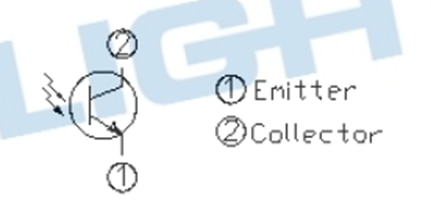
A 5MM Photo Transistor Phototransistor PT334-6C is selected as the clothes height detection photo receiver sensor.

Collector is the short leg/flat side. Max Ic = 20mA, rated Ic=3.5mA. Use a 1.5k resistor from 5v to collector.

image

The light source selected is a modified $1.79 USD COB LED flashlight

 image

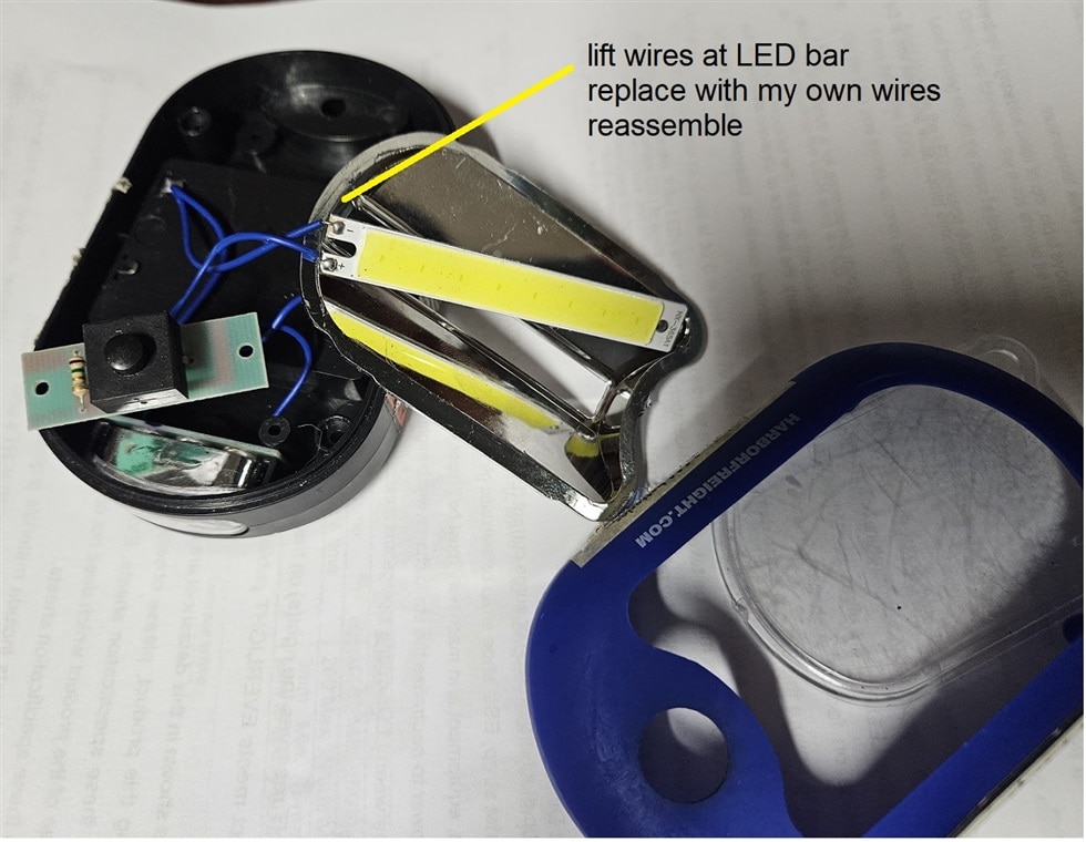
The COB LED bar does not totally behave like an LED. See attached table of Volts and amps applied to the COB LED bar

COB LED Volts applied

Measured COB LED mA

COB LED calc’d watts

2.3

0


2.4

0


2.5

1


2.6

12


2.7

39


2.8

76


2.9

118


3

173

.6

3.1

229


3.2

305

Nominal ?

3.3

393


3.4

481


3.5

600


3.6

700


3.7

740


3.8

840


3.9

1000

Getting toasty

4

1100

4.4


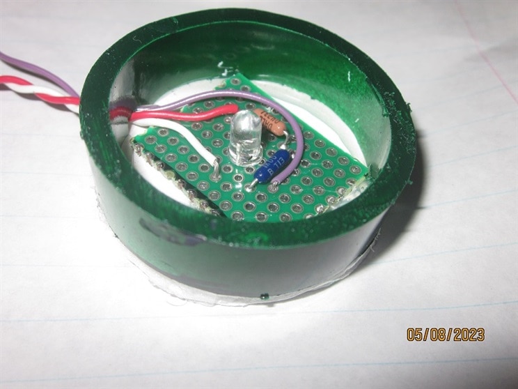
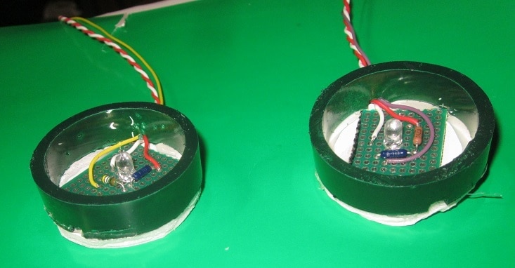
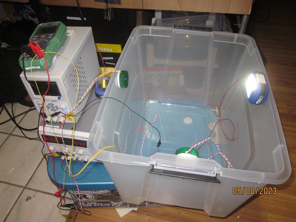
SETUP an experiment to read the phototransistor  collector to emitter voltage drop at different COB LED voltages, at actual distances between the phototransistor and light source the project will experience.

First built the phototransistor assembly with a protective shield around it 

image

image

The TEST HAMPER width distance is 15 inches.

COB LED Volts applied

Measured COB LED mA

Voltage drop across the phototransistor emitter to collector (5v VCC)

3

229

4.5

3.2

373

4.3

3.4

474

4.1

3.6

590

4

3.9

914

3.6

image

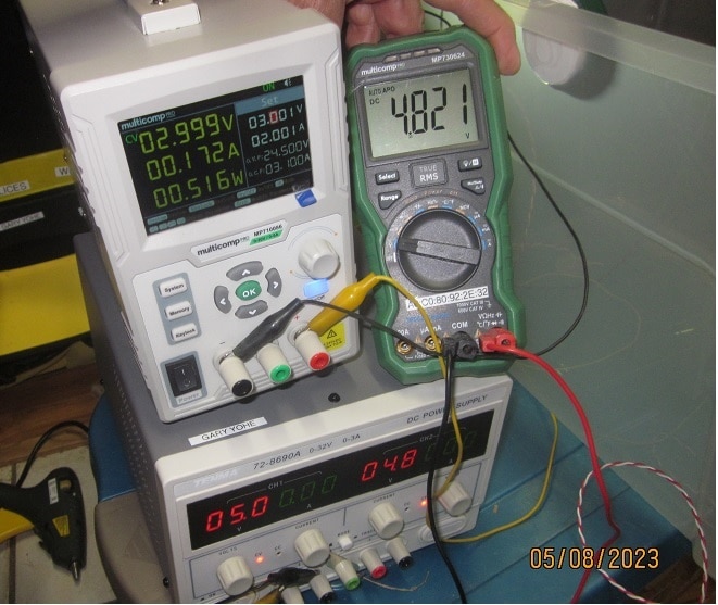
It sure is handy to have all these MultiComp DVMs and power supplies. 

 image

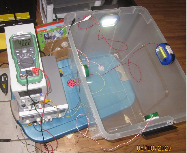
The length distance is 19 inches.

COB LED Volts applied

Measured COB LED mA

Voltage drop across the phototransistor emitter to collector (5v VCC)

3

152

4.84

3.2

287

4.7

3.4

415

4.6

3.6

590

4.47

3.9

870

4.3

 image

The conclusion seems to indicate the COB LED should use a 1 ohm current limit resistor if 5V is applied to the COB LED……………….BUT NOT SO FAST MY FRIENDS……

The next step of the design will use MOSFETs to switch on the COB LED bars.

This experiment measures the MOSFET voltage drop while it is turned on with the COB LED wired in series, at various currents.  

. MOSFET collector to emitter voltage drop

Measured mA

COB LED in series with MOSFET

.377

9

.46

32

.5

80

.46

150

.45

280

.43

440

.426

590

.423

780

.428

1000

My homemade IRD540 MOSFET modules, excellent as 1 quadrant motor controllers and hi load LED switches 

 image

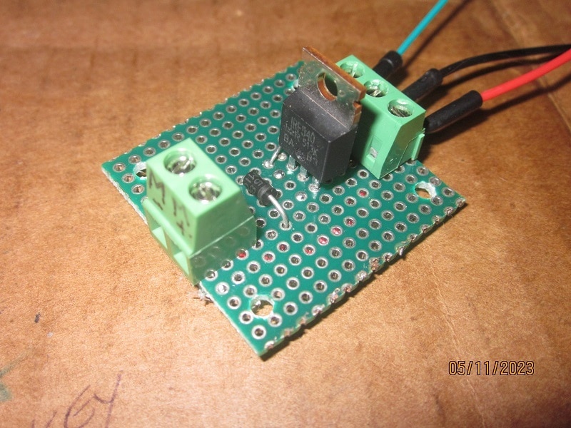
This data infers the MOSFET has a fairly flat .5V drop when turned on.

A ½ ohm series resistor could be used to limit current at 5V.  Rather than use a ½ ohm series resistor, the COB LED circuit will use a BUCK power supply to feed the COB LED + MOSFET about 4.6 Volts to drive the photo eye lights.    

 COB LEDs are pretty handy too.     

NOW onto the Arduino controls !!!!!!!

  • Sign in to reply
  • robogary
    robogary over 2 years ago in reply to DAB

    Thx. The final design will pulse the lights on for only a second,like a flashbulb, that's why I was trying to find the max without burning them out.

    Typical indicator type LEDS have a nominal current of 20mA, and max of 60 mA.

    I couldn't find that spec for COB LEDs, so that is partly why the experiment was done. I still don't know the nominal current for these COB LEDs, I assumed 300mA, but they've been up to 1300mA+ and haven't let out the smoke. At that current, they get warm pretty fast. The final design is adjustable so I can tune it.

    • Cancel
    • Vote Up 0 Vote Down
    • Sign in to reply
    • More
    • Cancel
  • DAB
    DAB over 2 years ago

    Nice update.

    You can always use PWM to cut the heat and current use.

    • Cancel
    • Vote Up 0 Vote Down
    • Sign in to reply
    • More
    • Cancel
  • robogary
    robogary over 2 years ago

    fabulous and insightful

    • Cancel
    • Vote Up 0 Vote Down
    • Sign in to reply
    • More
    • Cancel
element14 Community

element14 is the first online community specifically for engineers. Connect with your peers and get expert answers to your questions.

  • Members
  • Learn
  • Technologies
  • Challenges & Projects
  • Products
  • Store
  • About Us
  • Feedback & Support
  • FAQs
  • Terms of Use
  • Privacy Policy
  • Legal and Copyright Notices
  • Sitemap
  • Cookies

An Avnet Company © 2025 Premier Farnell Limited. All Rights Reserved.

Premier Farnell Ltd, registered in England and Wales (no 00876412), registered office: Farnell House, Forge Lane, Leeds LS12 2NE.

ICP 备案号 10220084.

Follow element14

  • X
  • Facebook
  • linkedin
  • YouTube