


 | Enter Your Electronics & Design Project for a chance to win a $200 shopping cart! Back to homepage | Project14 Home |
| Monthly Themes | ||
| Monthly Theme Poll |
Rotary LED Blinker
1 Introduction
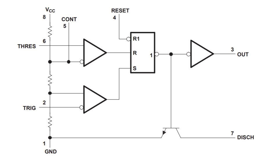
Basic digital circuit can start with 555 time
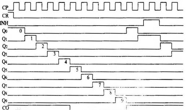
While CD4017 Decade counter can drive 10 output and it can count from 0 to 10 with internal logic
The output waveform shall be,
2 Schematic Drawing
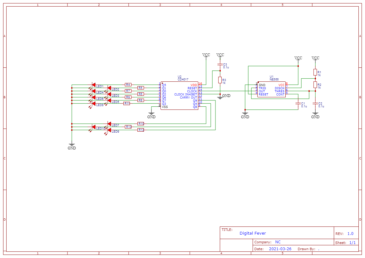
When NE555 time give timer pluse, the CD4017 can drive the LED on the ring one by one. Here is the schematic drawing.
3 PCB and Design
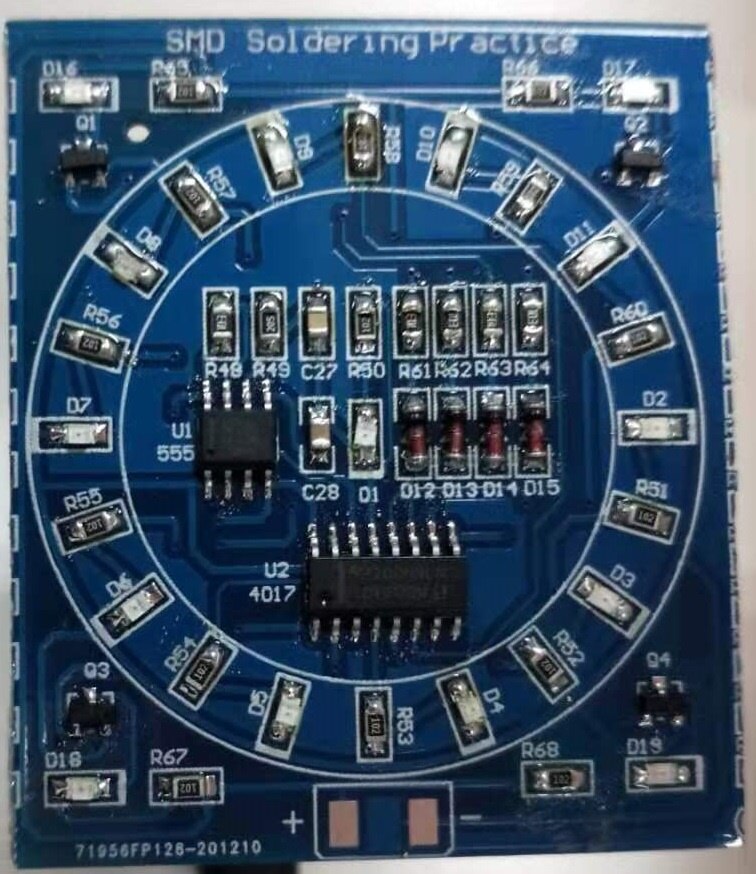
Here is the final result for the PCB and design. NE555 in SOP8 and CD4017 in SOP16
4 Summary
Q1~Q4 are thyristor to allow wider range of input voltage, this part is not show in shematics. D1 is inverted signal for D1~D10 around the ring.
This make the leds blink around the ring one by one.
Top Comments
-

hugohu
-
Cancel
-
Vote Up
+1
Vote Down
-
-
Sign in to reply
-
More
-
Cancel
Comment-

hugohu
-
Cancel
-
Vote Up
+1
Vote Down
-
-
Sign in to reply
-
More
-
Cancel
Children