element14 Community
element14 Community
    Register Log In
  • Site
  • Search
  • Log In Register
  • About Us
  • Community Hub
    Community Hub
    • What's New on element14
    • Feedback and Support
    • Benefits of Membership
    • Personal Blogs
    • Members Area
    • Achievement Levels
  • Learn
    Learn
    • Ask an Expert
    • eBooks
    • element14 presents
    • Learning Center
    • Tech Spotlight
    • STEM Academy
    • Webinars, Training and Events
    • Learning Groups
  • Technologies
    Technologies
    • 3D Printing
    • FPGA
    • Industrial Automation
    • Internet of Things
    • Power & Energy
    • Sensors
    • Technology Groups
  • Challenges & Projects
    Challenges & Projects
    • Design Challenges
    • element14 presents Projects
    • Project14
    • Arduino Projects
    • Raspberry Pi Projects
    • Project Groups
  • Products
    Products
    • Arduino
    • Avnet Boards Community
    • Dev Tools
    • Manufacturers
    • Multicomp Pro
    • Product Groups
    • Raspberry Pi
    • RoadTests & Reviews
  • Store
    Store
    • Visit Your Store
    • Choose another store...
      • Europe
      •  Austria (German)
      •  Belgium (Dutch, French)
      •  Bulgaria (Bulgarian)
      •  Czech Republic (Czech)
      •  Denmark (Danish)
      •  Estonia (Estonian)
      •  Finland (Finnish)
      •  France (French)
      •  Germany (German)
      •  Hungary (Hungarian)
      •  Ireland
      •  Israel
      •  Italy (Italian)
      •  Latvia (Latvian)
      •  
      •  Lithuania (Lithuanian)
      •  Netherlands (Dutch)
      •  Norway (Norwegian)
      •  Poland (Polish)
      •  Portugal (Portuguese)
      •  Romania (Romanian)
      •  Russia (Russian)
      •  Slovakia (Slovak)
      •  Slovenia (Slovenian)
      •  Spain (Spanish)
      •  Sweden (Swedish)
      •  Switzerland(German, French)
      •  Turkey (Turkish)
      •  United Kingdom
      • Asia Pacific
      •  Australia
      •  China
      •  Hong Kong
      •  India
      •  Korea (Korean)
      •  Malaysia
      •  New Zealand
      •  Philippines
      •  Singapore
      •  Taiwan
      •  Thailand (Thai)
      • Americas
      •  Brazil (Portuguese)
      •  Canada
      •  Mexico (Spanish)
      •  United States
      Can't find the country/region you're looking for? Visit our export site or find a local distributor.
  • Translate
  • Profile
  • Settings
Digital Fever
  • Challenges & Projects
  • Project14
  • Digital Fever
  • More
  • Cancel
Digital Fever
Blog Vidor Music Jukebox
  • Blog
  • Forum
  • Documents
  • Events
  • Polls
  • Files
  • Members
  • Mentions
  • Sub-Groups
  • Tags
  • More
  • Cancel
  • New
Join Digital Fever to participate - click to join for free!
  • Share
  • More
  • Cancel
Group Actions
  • Group RSS
  • More
  • Cancel
Engagement
  • Author Author: zst123
  • Date Created: 2 Apr 2021 10:26 AM Date Created
  • Views 2209 views
  • Likes 11 likes
  • Comments 3 comments
  • arduino mkr vidor 4000
  • mkr vidor 4000
  • digitalfeverch
Related
Recommended

Vidor Music Jukebox

zst123
zst123
2 Apr 2021

Vidor Music Jukebox

I'm proud to share my music jukebox project using the Arduino MRK Vidor 4000. It is my first project entirely using Verilog HDL!

imageimage


Hardware Build

These are my connections on a breadboard.

image

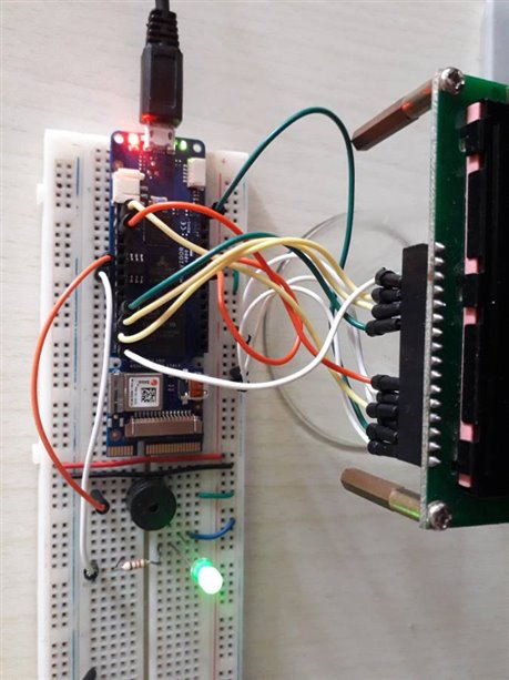
After that I soldered it onto a veroboard to make it permanent.

imageimage


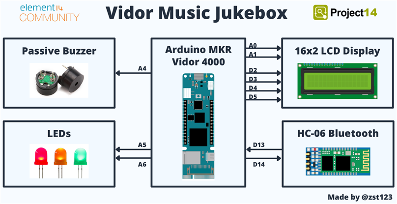
Here's a block diagram schematic of how it works.

image

Some setbacks faced


To start off, I was too adventurous and spoilt the Wifi module. When configuring the serial port RX/TX pins, I could communicate with the Wifi NINA module. After that, I added SPI pins and messed up the directions by assigning one of the pins in the wrong order. Due to my mistake, 2 output pins were directly assigned together and damaged the Wifi NINA module. Now the module does not respond anymore, it is completely dead. image


In the PCB schematic, the pins were wired directly from the FPGA to the Wifi Module without resistors. Maybe the Arduino team can improve on this and make it more fool-proof. If 2 outputs are configured together, a resistor should help to limit the current and prevent damage. Anyway, after ruining the Wifi module. I decided not to touch the Arduino code anymore, I'll make all the microcontroller pins into inputs (unused) and focus on FPGA in Verilog only and here is what I did...


Story of the build process

These are some useful guides to set up the Arduino IDE and Quartus Prime IDE

  1. https://www.arduino.cc/en/Tutorial/VidorGSVHDL
  2. https://www.arduino.cc/en/Tutorial/VidorQuartusVHDL/
  3. https://maker.pro/arduino/tutorial/how-to-program-the-arduino-mkr-vidor-4000s-fpga-with-intel-quartus-ide


Read up on the specifications of the MKR Vidor 4000

  1. https://www.element14.com/community/docs/DOC-92333/l/arduino-mkr-vidor-4000-pinout-samd21-pin-mapping-tech-specs-eagle-files-github-schematics-reference-links-faq-and-more
  2. https://www.baldengineer.com/arduino-mkr-vidor-4000-hands-on.html
  3. https://www.arduino.cc/en/Guide/MKRVidor4000


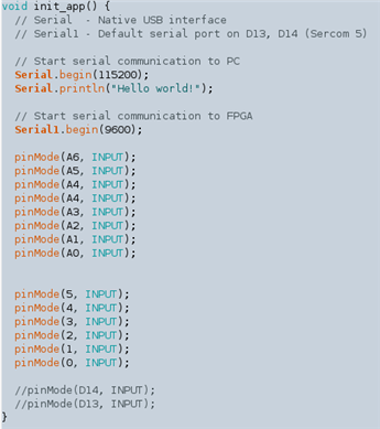
Firstly, I made this Arduino sketch to set all the pins to inputs. As I will be using the FPGA only, I do not need the microcontroller pins and by making it an input, it will prevent shorting the FPGA output to the microcontroller output. I also added Serial pins as later I will be using it for testing.

image


I am using this modified template with the Intel Quartus software. I am using the Verilog language to configure the FPGA.

https://github.com/wd5gnr/VidorFPGA


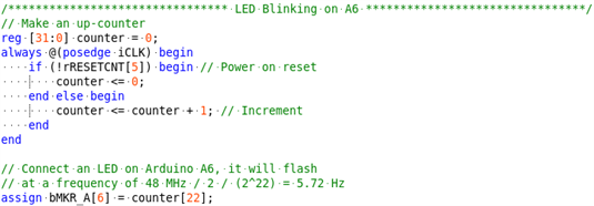
First I tried a flashing LED on pin A6. The clock is 48MHz from the SAMD microcontroller. In this case I made a counter and it used the 22nd bit.

image


Next I made a PWM fading LED on pin A5.

image


image

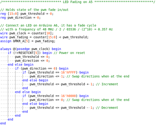
As you can see, both codes run simultaneously and my main struggle when I first started was understanding that the FPGA code is similar to building actual hardware.
ie. Important to think in terms of sequential circuits, state diagrams and combinational logic


Adding on, here's a buzzer setup where I used frequencies to play tones. This is a simple "Do, Re, Mi" test.

   imageimage

You don't have permission to edit metadata of this video.
Edit media
x
image
Upload Preview
image


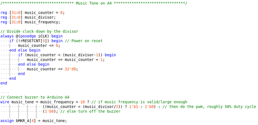
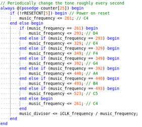
This website shows a list of frequencies for a music note used.

  • https://pages.mtu.edu/~suits/notefreqs.html
  • https://github.com/bhagman/Tone/blob/master/Tone.h

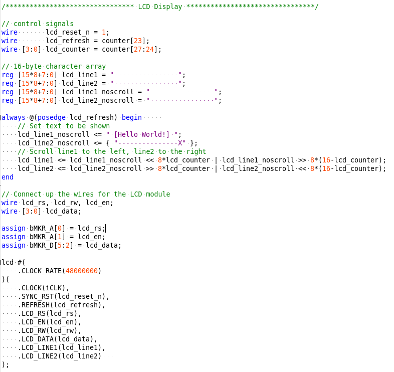
Code is getting pretty long so I wrote it into a separate Verilog file for the 16x2 Character LCD display.

It was challenging too to make the sequential logic and scrolling text across the screen.

image


image


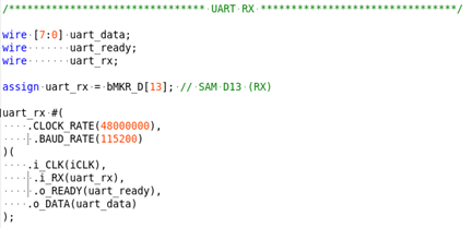
Lastly I added a UART module so that I can send commands from my PC

image


After playing around with the devices separately. Finally, I merged the code together to make the musical jukebox.

You don't have permission to edit metadata of this video.
Edit media
x
image
Upload Preview
image


I have published my project code on Github too!
https://github.com/zst123/Vidor-Music-Jukebox


Conclusion


image

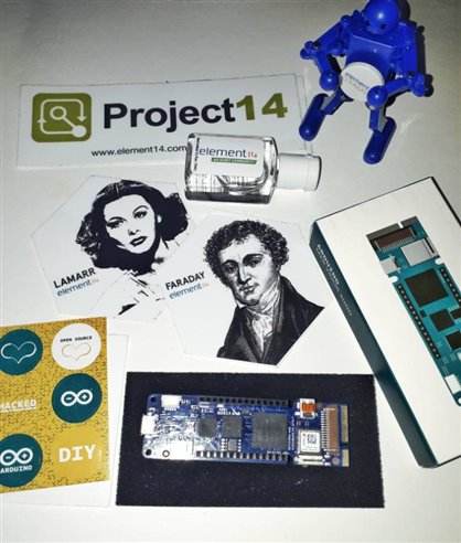
Thanks again to element14 for sending me an Arduino MKR Vidor 4000 for this project! Was great fun learning about FPGAs and I hope you enjoyed my blog post!

  • Sign in to reply

Top Comments

  • 14rhb
    14rhb over 4 years ago +3
    I think you've aced this project i.e. it is very good, bringing together several blocks into the FPGA. Well done.
  • zst123
    zst123 over 4 years ago in reply to 14rhb +3
    Thank you for your kind words! This board is pretty powerful and it was fun indeed. I just ordered a micro HDMI adapter, hopefully I can try out the display capabilities in my next project!
  • dubbie
    dubbie over 4 years ago +2
    Manzel, A great project. It has been a long time since I have seen such HDL programmes. I came over all misty eyed. I'm not sure I would want to go back to writing VHDL but I did have fun when I was doing…
  • dubbie
    dubbie over 4 years ago

    Manzel,


    A great project. It has been  a long time since I have seen such HDL programmes. I came over all misty eyed. I'm not sure I would want to go back to writing VHDL but I did have fun when I was doing it.


    Dubbie

    • Cancel
    • Vote Up +2 Vote Down
    • Sign in to reply
    • More
    • Cancel
  • zst123
    zst123 over 4 years ago in reply to 14rhb

    Thank you for your kind words! This board is pretty powerful and it was fun indeed. I just ordered a micro HDMI adapter, hopefully I can try out the display capabilities in my next project! image

    • Cancel
    • Vote Up +3 Vote Down
    • Sign in to reply
    • More
    • Cancel
  • 14rhb
    14rhb over 4 years ago

    I think you've aced this project i.e. it is very good, bringing together several blocks into the FPGA. Well done.

    • Cancel
    • Vote Up +3 Vote Down
    • Sign in to reply
    • More
    • Cancel
element14 Community

element14 is the first online community specifically for engineers. Connect with your peers and get expert answers to your questions.

  • Members
  • Learn
  • Technologies
  • Challenges & Projects
  • Products
  • Store
  • About Us
  • Feedback & Support
  • FAQs
  • Terms of Use
  • Privacy Policy
  • Legal and Copyright Notices
  • Sitemap
  • Cookies

An Avnet Company © 2025 Premier Farnell Limited. All Rights Reserved.

Premier Farnell Ltd, registered in England and Wales (no 00876412), registered office: Farnell House, Forge Lane, Leeds LS12 2NE.

ICP 备案号 10220084.

Follow element14

  • X
  • Facebook
  • linkedin
  • YouTube