


I recently went through this blog post
Creating a function generator from an Arduino board that can be programmed by means of a VT100 serial terminal looks a good idea to. After all, it's a very common scenario to have a PC on your workbench and, if you don't have a PC, you have a Raspberry Pi or another Linuxe-based board. So it makes a lot of sense to use the PC as your instrument's user interface. And if the user interface is available through a VT100 serial connection, than you have created the universal user interface!
ANSI escape sequences
When I say "VT100 serial connection", it's not 100% correct. Actually VT100 is just one of the first terminals to support ANSI escape codes to control cursor, change text and background color, and perform many other tasks that allows you to create a very basic graphic UI, However the VT100 added a number of extended codes to support special features light controlling the keyboard LEDs that led this proprietary version to uptake the standard version of the ANSI escape codes and become the de-facto standard of terminal emulators
Escape sequences are commands prefixed by the character sequence
ESC [
This sequence is also called Control Sequence Introducer (CSI). CSI is follwed by a number of character that defines the command to execute and eventually the command parameters. For example, to move the cursor down the device the terminal emulator is connected to will send the following sequence of characters
ESC [ 1 B
or
CSI 1 B
"1" is a parameter that tells the terminal the number of cells to move the cursor. The complete list of escape sequences is available here
So from this short explanation it's clear that terminal emulator must be able to interpret correctly escape sequences. This means you need to install a terminal emulation software on your PC. I think MobaXTerm is really great project and worth to be evaluated
Arduino and VT100
I found a complete "server-side" implementation of VT100 protocol here. This library can not be installed from the Arduino IDE's library manager. To install, just
- download the source code as a zip file
- unzip in c:\Users\<Your user>\Documents\arduino\libraries
- Restart the Arduino IDE
Using the VT100 terminal functions, is quite easy
- define the BasicTerm object
#include <BasicTerm.h>
BasicTerm term(&Serial);
- Initialize the Arduino serial port
Serial.begin(115200);
- initalize the terminal
term.init();
- start using the terminal object
    term.cls();
    term.show_cursor(false);
Implementing the user interface
By leveraging the terminal functions, I created some simple classes that implement the UI basic components. Currently I implemented only the components I need for this specific project but the software has been designed to be extended. Currently, the following classes are available
- label
- input field to enter a numeric value
- combo box
- "button"
- form, that draws the frame and some other graphical elements and supervises the UI components it contains
Each UI component is derived from a base class, called VTItem so that all UI components can be handled by the form with no regard of the actual UI component type. In software engineering jargon, VTItem is the interface and here we are applying the Liskov Substitution Principle (aka LSP). The VTItem interface expses the following methods
virtual void draw()
draw the UI component
virtual void apply()
confirm the value being edited
virtual bool handleKey(int key)
handles the key and update the UI accordingly
virtual bool canFocus()
return true if the UI component can take the focus, false otherwise (e.g. a label)
virtual void setFocus(bool focus)
gives focus to or gets focus from the UI component
All derived UI components need to implement a specialized version of these function
The user interface
With the above-mentioned components, I created the following forms
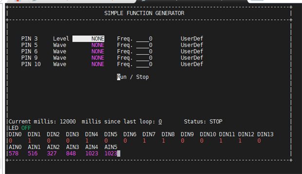
At the top, there are 5 lines to configure the function to generate on each PIN. In this case, I am using a Arduino Nano 33 IoT and I selected 5 of the pins that support PWM.
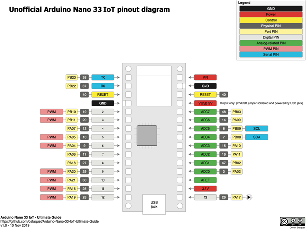
https://github.com/ostaquet/Arduino-Nano-33-IoT-Ultimate-Guide
From the combo box, you can select the waveform to generate, namely
- None (pin not used)
- Square
- Triangle
- Sawtooth
- User defined
For square, triangle and sawtooth, one can enter the desired frequency. Note that the square waveform is not generated using a PWM, but by driving the pin
Triangle and sawtooth waveforms are generated using PWM and the TurboPWM library. More details are below
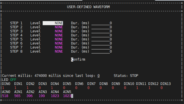
"User defined" waveform is created as a sequence of "high" and "low" logical states. Such steps are configured by means of the following form
PWM and analog signals
The Arduino Nano does not have a DAC converter to generate the analog values of a sinusoidal waveform. The solution is to use PWM and a low-pass filter.
You can find a great explanation at this link
https://create.arduino.cc/projecthub/Arduino_Scuola/build-a-simple-dac-for-your-arduino-4c00bd
The Arduino Nano's PWM peripherals (and, in general, all the SAMD21-based Arduino boards) can be programmed by means of the TurboPWM library, which allows you to generate PWM signals with any frequency. According to the TurboPWM documentation,
- For the Arduino Nano 33 IoT, you need to initialise timer 1 for pins 4 and 7, timer 0 for pins 5, 6, 8, and 12, and timer 2 for pins 11 and 13;
- For the Arduino Zero (untested), you need to initialise timer 0 for pins 3, 4, 10 and 12, timer 1 for pins 8 and 9, and timer 2 for pins 11 and 13;
- For the Arduino MKR series (untested), you need to initialise timer 1 for pins 2 and 3, timer 0 for pins 4, 5, 6 and 7, and timer 2 for pins 8 and 9;
- For the Adafruit Trinket M0, you need to initialise timer 0 for pins 0 and 2, and timer 1 for pins 3 and 4.
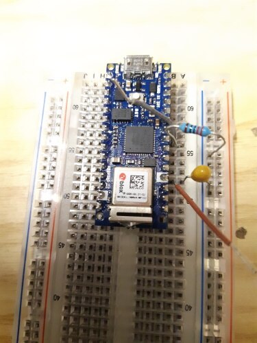
I am going to use a passive filter, because I expect to have loads that takes less than 10mA. So the circuit for the low-pass filter is very simple:

The cut-off frequency is given by the formula

When designing the low-pass filter, there is a fundamental trade-off to consider:
A lower cutoff frequency means less ripple and longer settling time; a higher cutoff frequency means more ripple and shorter settling time. So we have to think about your application and decide if you want a DAC that is more responsive or less subject to output ripple.
I will configure the PWM to have a frequency of 2 kHz
  pwm.setClockDivider(1, false);
  pwm.timer(0, 1, 750, false);
  pwm.enable(0, true);
and I will design a low pass filter that about 10 Hz. With R = 6,8 kOhm and C = 2.2 uF, the cut-off frequency is 10,64 Hz, which is good
Back to the code, the analog waveforms are generated using lookup tables generated using this site
https://www.daycounter.com/Calculators/
The Arduino application will update the PWM, as time passes, with the values in the lookup table
  // get the current microseconds since start
  long us = micros();

  // how many microseconds since the run command?
  long usDelta = us - runStart;

  // usStep is the number of microseconds for each of the 128 steps in the
  // lookup table. usStep is calculated as the waveform period divided by 128
  long lIndex = usDelta / ps->usStep;

  // get the index to the lookup table
  int index = (int)(lIndex & 0x7F);

  // get value from table
  int value = table[index];

  // write to PWM
  if (value != ps->value)
  {
    int ivalue = value * 1000 / 255;
    pwm.analogWrite(pin, ivalue);
    //analogWrite(pin, value);
    ps->value = value;
    ps->index = index;
  }
The final setup is shown in picture below: I have just the Arduino Nano and the low-pass filter
This is the output for a 10 Hz triangle waveform

Looks good, but the ripple is quite high (about 100 mV)

Here is video with the SSFG in action
Conclusions
The final outcome of this project is not very satisfactory and a lot of work needs to be done to implement a better low-pass filter and to shift level of the waveforms (the desired RMS value for a sine wave is 0V...)
However I think I achieved two major goals with this project
- I created a framework to will allow to create user interfaces using ASCII escape codes
- I created an interesting tool to simulate specific sequences of logical signals. This could be very useful when you are developing an application and want to stimulate it with a given sequence of 1s and 0s. It would be interested to add some logic like "switch output x to high 100 ms after input y switches to low"ù
Source code is available at
Top Comments