


Introduction
Current measurement can be really awkward when working with circuits. Voltage measurements are (usually) straightforward, but when it comes to current measurements the story is different. One typical approach is to insert a known resistance by breaking the circuit, and then measuring the voltage across it. This is difficult if one end of the resistor is not at ground potential, because oscilloscope probes are (usually) designed with the ground leads all connected together, and it will damage things if the grounds of different channels on the oscilloscope are connected to different parts of the circuit.
This project describes a very sensitive home-made current probe that doesn’t require a known resistance to be inserted. It has not been fully characterized but the initial results are reasonably promising. It was tested at currents of the order of single-digit microamps up to 10mA (it can be assembled for higher current ranges if desired), and it functions from DC to around 20kHz, and is fully isolated.

It is based around a very exotic magnetic field sensor known as a fluxgate magnetometer. Ordinarily this is quite difficult to build due to the requirement for hard-to-find mu-metal and a mix of analog and digital electronics. However, Texas Instruments offers an entire fluxgate magnetometer-on-a-chipfluxgate magnetometer-on-a-chip and an evaluation boardevaluation board. With some effort it is possible to build a current sensor or probe with it. It makes a handy test tool for measuring current in a circuit, in a less intrusive way than normal.
What is a Fluxgate Magnetometer?
There are several ways to make magnetic field sensors, and the fluxgate magnetometer offers very impressive sensitivity. There are slightly different topologies of fluxgate magnetometers, but in a nutshell they consist of windings around a core. If we use a Lego wheel tyre to act as a pretend core then ‘Excitation’ and ‘Sense’ windings can be placed around it as shown in the photo (the windings are the yellow and green wires in the photo).

If we consider the core to look like two semi-circular half cores each with half of the excitation winding on it then an AC signal of sufficient power is applied such that each half-core reaches saturation (i.e. the magnetic field cannot increase any further) in both directions alternately as the AC signal changes direction.
The other coil, the green sense coil, is wound around the outside like a wrapper to the entire thing. When the core is in saturation the magnetic field does not change, and therefore there is no voltage across the sense winding. In other words, a changing magnetic field is needed to induce a voltage in the sense winding. The clever bit occurs when there is an additional magnetic field present (either created locally with another winding, or any existing nearby magnetic field as shown in blue in the photo above). Because the two half cores have their excitation windings in opposite directions, ordinarily the magnetic fields cancel out. But in the presence of a magnetic field, when the AC excitation signal direction changes, one half core will exit out of saturation slightly sooner than the other half core, or slightly later than the other half core, depending on the direction of the additional magnetic field. When this occurs, there is no balancing out of the magnetic fields! And since the magnetic field is no longer zero, during this time that the field is changing, a signal is generated in the sense winding. It is an easy-to-detect signal because the asymmetry caused harmonics of the excitation signal frequency, and it can be detected using analog electronics.
The basic design can be modified by having yet another winding known as the Compensation coil and an amplifier to drive it such that it nulls out the external magnetic field. The output of the compensation coil therefore becomes the output of the fluxgate magnetometer.
Fluxgate magnetometers have exceptional sensitivity and can detect the earth’s magnetic field. Texas Instrument has several ICs that contain all the signal generation and signal processing required to construct a fluxgate magnetometer. There is also one IC in the range which even integrates the core inside the package. I decided to use that IC for this project. All I needed to worry about was how to generate the external magnetic field, and that is possible with an external winding.
The diagram here from TI’s website shows the internals of the IC. All of this is integrated into a tiny square 4x4mm package.

Why build a Current Sensor? What is a Current Sensor? What types are there?
The voltage across two points is easy to measure with a voltmeter/multimeter. If the voltage is changing over time then an oscilloscope can be used too.
The current through a wire is harder to measure; it often entails breaking the wire and attaching an ammeter/multimeter set to measure current. If the current is changing over time then one way to observe this is to insert a fixed value resistor in series with the wire, so that a potential difference (voltage) is created across the resistor. The voltage will be directly proportional to the current flowing through the resistor, and so then the problem has been reduced to one of observing a voltage which is easy to do with an oscilloscope. However, by adding a resistor the circuit has been modified slightly. To minimise this, the resistor is usually chosen to have a very low value. But if the value is too low then the measured voltage will be very low too.
Another issue is that sometimes it is desirable to have a way of measuring current with isolation; this is especially necessary if it is desired to measure current through different parts of the circuit simultaneously using an oscilloscope (the probe ground connections are all connected together and to ground usually).
So, resistors as current sensors can have limitations. Another type of current sensor looks very much like a transformer. It can work very well but usually just for AC signals; a DC component is not detected because there is no change of flux and therefore no voltage induced in the secondary coil.
Yet another type of current sensor is based around a hall effect sensor which detects magnetic fields. It functions from DC to tens or hundreds of kHz. It is primarily used for measuring currents in the tens or hundreds of milliamps and upwards.
Like the hall effect based sensor. a fluxgate magnetometer has the capability to allow the creation of sensors for both AC and DC signals because it measures the magnetic field, not an induced current like a transformer does. Unlike a hall effect sensor, it can be extremely sensitive.
It is possible to purchase current probes for oscilloscopes that are based on the fluxgate magnetometer principle but they cost thousands of pounds/dollars. This project uses a similar principle but only works to a low frequency range of about DC to 30kHz. This could be useful for examining dynamic current consumption of parts of circuitry. It is no useful for examining many modern DC-DC converter circuits however because they operate at very high frequencies nowadays.
This project doesn’t really compare to a commercial current probe for an oscilloscope, because they will function to tens or hundreds of megahertz.
However, this project is far cheaper and still offers some benefits. It has isolation just like a commercial probe. The other main advantage is the very high sensitivity (around 800 volts per amp sensitivity with a simple circuit).
Building the Sensor
As mentioned the fluxgate magnetometer resides on a single chip, so there is no work to do there. It is in a 4x4mm surface mount package (QFN) which is awkward to work with however an evaluation board is available with it pre-soldered. I used that.
To construct the magnetic field, I used a ferrite core; some experimentation here could be useful, I used Amidon FT-50-43 in my tests but others could be used too. Several will need to be purchased because it is almost inevitable that they will be damaged at the next step, the yield is very low. A slot was cut into the core, so that the 4mm fluxgate magnetometer could be a snug fit. With hindsight I didn’t need to cut all the way into the core, just the thickness of the IC would have been sufficient. Anyway, attempting to cut or file the core will almost certainly result in it breaking apart unless lots of care is taken. I couldn’t find a perfect strategy, but 3D printer owners could construct a jig to precisely hold the core during the cutting operation.
Enamelled wire was wound around the core; I picked 40 turns as a ballpark to experiment at, and 0.2mm diameter wire fitted well. A bit of glue can secure the ends from unravelling. The resistance of the coil is about 0.4 ohms, but with slightly thicker wire (which would fit) the resistance can be reduced. 0.3mm diameter wire would halve the resistance for example.

Next, it needs to be secured to the fluxgate magnetometer board. Since I wanted to experiment, I just used blu-tack (temporary putty) for now instead of a permanent glue. Although it looks like it might function poorly with such a trivial attachment, the result is very stable. The measured current does not fluctuate.

Initial Tests
In use, the circuit would be broken at the point where the current needs to be measured, and the ends of the wound coil would be attached into the circuit. For the tests below, it was decided to use a resistor and a signal generator as the circuit under test. The circuit was broken and the current sensor was inserted in. The output of the current sensor went to an oscilloscope. I borrowed an oscilloscope from work for this, it needed the big gun Tektronix MDO3000 so that I could use some advanced math features and waveform processing capabilities to make my life easier.
So, this was the topology:

Although there was no need to connect the signal source to the oscilloscope, it was connected to measure the voltage across the input resistor, to determine how much current was flowing through the current sensor input. For all the traces below, the important trace is the yellow trace which is the output from the current sensor. The blue input trace is just a reference to see what the input signal looked like. For these initial tests, even though the current sensor responds to DC, the oscilloscope was set to AC input because the output has an approximate 2.5V offset. The oscilloscope bandwidth was set to 20MHz for these tests.
All measurements are approximate, since this was just an experimental circuit.
100Hz, 1mA RMS Input current
As an initial test, a low frequency (100Hz) was used. From the measurements at the bottom of the ‘scope display you can see that the input signal was 100mV RMS and the output was around 43mV RMS. Since the input blue trace was measured across a 100 ohm resistor (approximately), that means the current through the resistor was 1mA RMS. The yellow trace shows that the current sensor therefore has a sensitivity of just over 40 volts per amp (i.e. 43mV divided by 1mA).

There is some noise on the output, but that could partially be due to the measurement since it is a low-level signal (43mV RMS) that is being observed.
To examine if the trace could be cleaned up a bit, averaging was turned on in the MDO3000. At a default averaging setting (16 or 32 averages, I need to double-check), this is what the output looked like:

So, for repetitive current draw at around 1mA RMS and at low frequency, it is possible to get a very clean output from this solution.
10kHz, 100uA RMS Input current
As a more extreme test, the frequency was increased to 10kHz, and the current was reduced to 100uA. At this level I would expect the output to be noisier, and perhaps observe some phase difference due to delay between input and output, and see a change in gain perhaps if the frequency response is not flat. Here is the observed result:

With averaging turned on, this was the result:

The output is about 3.9mV RMS which corresponds to a sensitivity of 39 volts per amp. So, compared with the 100Hz 1mA RMS traces earlier, this result shows that the frequency response is fairly flat to at least 10kHz. These measurements were not precise, these are just quick measurements to characterize the behaviour slightly.
Building an Amplifier
By now it was clear that the output benefits from an amplifier to make best use of it. I used an Analog Devices AD8226AD8226, assembled into a 20x gain instrumentation amplifier on a breadboard. There isn’t a lot to the circuit (I’ll draw it up if there is interest), but basically it consists of a 2.7k resistor to set the gain, and a couple of 100nF capacitors for supply decoupling. It was powered from +10V/-10V supplies, and the 2.5V reference output from the DRV425 board was used as the offset input to the amplifier. Some trimming would be useful to completely null out the 2.5V offset, but it was mostly nulled out, enough for me to switch to DC on the oscilloscope, for some of the tests below. For a real design the frequency response of the amplifier should be confirmed to be flat; I didn’t characterise it since it was just a quick hack on a plastic breadboard, and I could always circle back if I saw any anomaly in the subsequent tests.

Tests with the Amplifier
The diagram here shows the test topology:
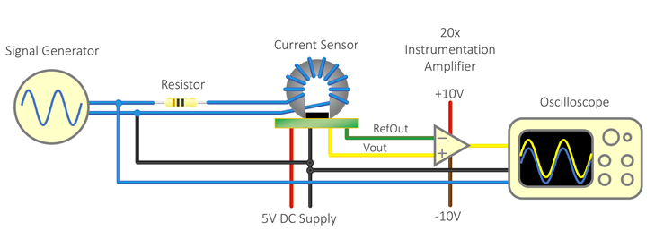
10kHz, 100uA RMS Input Current
With the amplifier connected, the output was clearer and of course larger. I was no longer in the noise with the oscilloscope gain having to be set at max. I use a 1kohm resistor for this test.

The voltage across the 1kohm resistor is about 100mV RMS according to the blue measurement on the oscilloscope, so that corresponds to 100uA RMS input current. The yellow output is about 81mV RMS which means the sensitivity with the amplifier is 800 volts per amp.
With averaging turned on, the trace was again cleaner as expected:

I kept the averaging on, and with a square wave input (again at 10kHz, 100uA RMS), the bandwidth effects were apparent, but still a very clean and usable result:

10kHz, 10uA RMS Input Current
Since the results at 100uA RMS were fairly clean and usable provided some averaging was possible, I was curious to see if 10uA RMS was usable too. This is quite a small current draw! To put it in perspective, an AA sized battery (2000mAH) should (self-discharge excluded for this hypothetical experiment) last for 16 years if attached to a circuit drawing 10uA! Here is the result with averaging turned on:

10kHz, 10mA RMS Input Current
Since the low-level current measurements were not bad, I wanted to explore higher current values. I switched off the averaging and with the input current set to 10mA, I needed to increase the amplifier supply voltage from +10V/-10V to +15V/-15V to stop clipping, and the result is shown here:

Summary
For the limited 1000:1 range of around 10uA to 10mA the circuit functioned well. It allows for fully isolated measurements from DC to 10kHz or beyond. While it would be quite useless for DC-DC converter measurements, it could have uses in developing low power circuits where current in sleep periods needs to be monitored as well as current during wake-up periods.

By experimenting with the winding and amplifier, different current ranges could be implemented. I’d love to see what uses others could find for such a current measurement device with these characteristics.
I really enjoyed experimenting with the fluxgate magnetometer; it is awesome to have such high sensitivity in a low-cost, tiny device. I'm hoping to try non-current-sensing applications with it too.
Top Comments