


Introduction
I am one of the road testers for the Infineon DC Motor Shield w/ TLE94112EL for Arduino and this project shows the testing platform I developed to test the features of the board shield, but it is also useful to test the DC motors performance, as well as other motor controller boards for Arduino.
According to me, carrying out a testing on the road of this platform based on the Infineon TLE94112 IC requires a versatile and flexible platform to make possible all the tests without building a lot of unreliable breadboarded stuff with loose wires. Moreover, in order to widen the range of possible tests making the platform reusable in the future you need to add only few extra components.
A full test of the TLE94112LE shield for Arduino based on this platform will be published in the Road Test section.
The Project
Planning the Design
The idea of making an interactive testing platform evolved as I progressed analyzing in depth the shield features on several Arduino compatible platforms: Arduino UNO R3 , Chipkit PI and the Infineon XMC1100 Boot . All these platforms were reliable with no t special issues by the TLE94112 shield; for the final development I opted for the Infineon board due the better ARM MCU, which is faster and with more available flash and RAM memory (ARM Cortex M0 32 bit, 16Kb high-speed RAM, 64Kb Flash memory) I should admit that the better performance of this board compared to the Arduino UNO kept as reference.
Testing motors
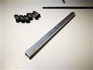
To create a reference for the test platform I chosen 6 brushed geared micro-motors with electrical characteristics included in the acceptable ranges of the TLE94112LE IC assembled together on an Aluminium square bar.
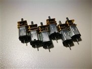
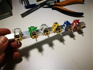
To that aim, I used cheap motors from Pimoroni with the following characteristics:
Free-run current @ 6V: 60mA (max 120mA) - in some conditions can generate an overcurrent that is useful to test the error registers of the TLE94112
Stall torque @6V: 2.5Kg/cm
Stall current @6V: 900mA (TLE94112LE max current per half-bridge is just 0.9A)
Gear ratio: 298:1

A small 3D printed object has been designed to make visible the rotation of the motors.
Control I/O
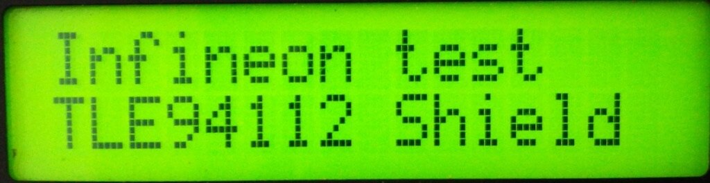
Using a terminal to control the shield seemed immediately the right choice as the available control options open a wide scenario of many motion possibilities. The problem arose when I saw that some status information and configuration updates need continuous and immediate feedback. To solve this problem, an LCD display has been added to the testing board.

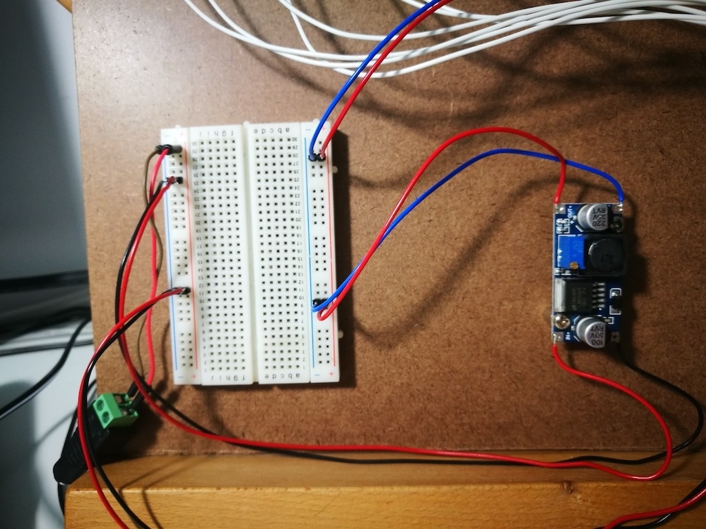
DC/DC Regulator
To provide the right power supply to the TL94112 a separate power line has been set through a DC/DC power regulator.

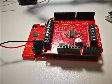
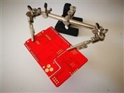
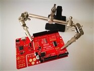
Design in practice
The working version of the design evolved around the features of the board I have experienced during the first phase of the hardware testing growing its complexity. The images below show the most meaningful steps.
| {gallery} Platform design evolution |
|---|
|
|
|
|
|


The Testing Platform
The last element added to the testing platform is a 50K potentiometer connected to the analog port 0. That will be used by the software when you need to read dynamic values (e.g. the manual duty cycle). The diagram below shows the components connection.

The Software
The hard part was developing the software, that required a lot of revisions, 37 pushes on the GitHub repository, but nowat last it is available as Open Source under the LGPL 3.0 license: https://github.com/alicemirror/TLE94112LE
Software Design
The software is divided into functional blocks as listed below
- Main Sketch: initialize and setup the system. The main loop controls the TLE94112 through the Arduino library (via SPI protocol on PINs 8 and 10), the analog input and the parser, the messaging via the serial terminal and the LCD display.
- Commands: definition of all the serial commands response messages and all related to the parsing.
- MotorControl: the class interfacing the (thanks to) Infineon TLE94112 Arduino library with the high-level methods used by the serial commands
We'll see them in detail in the next chapters.
1. Main Sketch
I tried to reduce as much as possible the definition of global variables and constants in the main sketch. The only pre-processor definitions in the TLE94112LE.ino are limited to the global flags driving thebehaviorr of the program in the mainLoop() and the symbolic constants definitions strictly related to the application logic to avoid confusion and better readability and making the MotorControl class fully reusable in other projects.
//! Max analog reading range with a 50K potentiometer
#define MAX_ANALOG_RANGE 1024
//! Min analog reading range with a 50K potentiometer
#define MIN_ANALOG_RANGE 0

//! Duty cycle analog read should be ignore (bypass the analog reading)
#define ANALOG_DCNONE 0
//! Duty cycle analog read should be assgined to DC min
#define ANALOG_DCMIN 1
//! Duty cycle analog read should be assgined to DC mAX
#define ANALOG_DCMAX 2
//! Duty cycle analog read should be assgined to DC manual reading
#define ANALOG_DCMAN 3
A special note about the preprocessor directive _SERIAL_ECHO:
#define _SERIAL_ECHO - all commands are echoed to the serial terminal as shown in the example below
Serial output
setting all
Direction ccw
setting none
setting m1+
PWM: 80
setting dc80
set accel
setting dc100
#undef _SERIAL_ECHO - only wrong commands are notified on the serial terminal
Serial output
wrong command 'mindc'
Main loop() structure
The main loop control the logic of the application. It is organised in three functional blocks checked sequentially every cycle depending on the status of the top flags and the data availability on the serial port (Tx/Rx, Pin 0 and 1)
Motors running status block
This block is checked only if the system status is running (start command). Every loop cycle when the motors are running it is checked for the presence of some error on the TLE94112LE registers and eventually errors are notified on the serial terminal
  // Check if at least one motor is running to test the error status
  // Note: It is possible to isolate the error status, if any,
  // for any motor. Here we make a simplification and check over
  // the motor without filtering
  isRunStatus = false;
  for(j = 0; j < MAX_MOTORS; j++) {
    if(motor.internalStatus[j].isRunning) {
      isRunStatus = true;
      j = MAX_MOTORS; // Force exit from loop
    } // check for running motors
  } // motors loop
  // If at least one motor is running check for diagnostic
  if(isRunStatus) {
    if(motor.tleCheckDiagnostic()) {
      //! Show the error star
      lcdShowError();
      motor.tleDiagnostic();
      lcdClearError();
    }
  }
Serial parsing block
If there are data available on the serial, the parser function parseCommand(String) is launched to check the command (or return a command error).
Serial commands are received as String terminated by CR=LF characters to be supported by any terminal or common serial connection. The last two terminating characters are removed before the string parsing.
All the commands and parser related strings are defined in the header file commads.h
Analog reading block
There are three conditions that enable the reading of analog values:
- ANALOG_DCMIN User is setting manually via the potentiometer the minimum duty cycle value for one of the three PWM channels
- ANALOG_DCMAX User is setting manually via the potentiometer the maximum duty cycle value for one of the three PWM channels
- ANALOG_DCMAN User can change manually via the potentiometer the current duty cycle value for the PWM channel(s) enabled for manual duty cycle
Other functions in the main sketch
The main sketch also includes the functions to control the optional LED (on pin 12) and the LCD layout control functions.
LCD layout
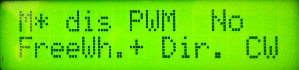
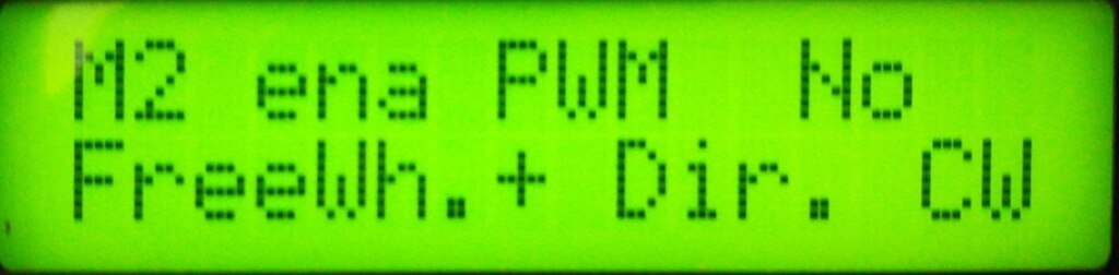
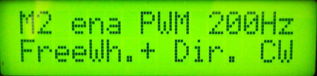
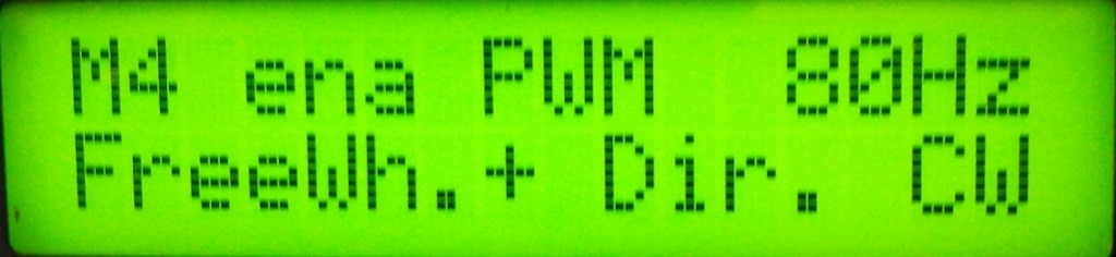
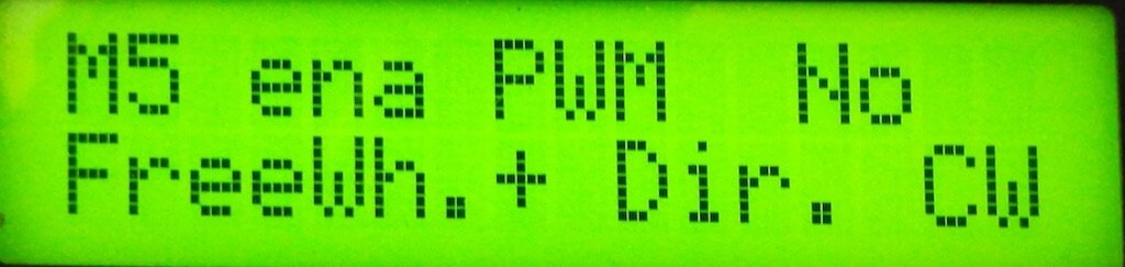
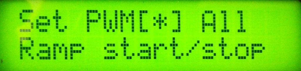
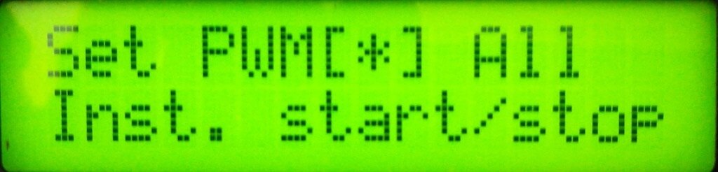
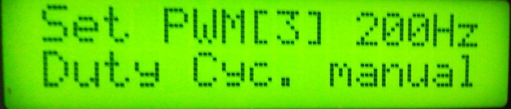
For obvious size reasons the LCD shows several layouts depending on the conditions using a layout with abbreviations; whenever possible, more readable strings have been used. The shortened symbols used by the LCD are listed below:
- M1, M2, M3, ... M6 Set the corresponding motor
- M* Set all the motors with the same parameter
- PWM[1] 80Hz, PWM[2]100Hz, PWM[3] 200Hz Set one of the three PWM channels (assigned to a fixed frequency)
- CW/CCW Clockwise/Counterclockwise direction of the selected motor(s)
- FreeWh+/FreeWh- FreeWheeling active enabled/disabled for the selected motor(s)
- DCMin Minimum duty cycle value for the selected PWM channel(s)
- DCMax Maximum duty cycle value for the selected PWM channel(s)
- ena/dis Selected motor(s) set as enabled or disabled
- Ramp Set acceleration and deceleration for the selected PWM channel(s)
- Inst. Set instant starting for the selected PWM channel(s)
The gallery below shows and example of several LCD layouts
| {gallery} LCD Layout examples |
|---|
|
|
|
|
|
|
|
|
|
2. MotorControl Class
The MotorControl C++ class is pat of the software, uses the TLE94112 Arduino Library by Infineon and is built around the files motorcontrol.cpp, motorcontrol.h and motor.h (extra preprocessor definitions). The class itself is structured through two level methods.
For the complete methods of the class and full documentation refer to the software available on the GitHub repository
MotorControl - Hardware control methods
The hardware control method interfaces directly the features of the hardware shield exposed by the TLE94112 Arduino library.
MotorControl:: tleCheckDiagnostic(void)
MotorControl::tleDiagnostic(int motor)
MotorControl::tleDiagnostic()
Check the diagnostic status and send the corresponding error message to the serial terminal (if any)
MotorControl::motorConfigHBCCW(int motor)
MotorControl::motorConfigHBCW(int motor)
and others similar to configure half bridges direction and the other parameters, the PWM channel, duty cycle etc.
MotorControl - High level methods
The hight level methods interfaces the commands calling recursively after filtering potential errors, This avoid internal problems or unexpected behaviours or hardware damages.
Every parser command call one of the high level commands of this class.
3. Commands Description and Syntax
Excluding the potentiometer on the board all the controls are sent via terminal through a USB-to-serial connection. When the system is in running mode it can accept configuration commands that will be effective after a stop and start call.
If errors occur while the system is running these are shown in detail on the serial terminal and are notified on the LCD screen
The available commands are listed below:
Direction control
- cw : clockwise rotation
- ccw : counterclockwise rotation
- accel : enable the acceleration when motor start
- noaccel : disable the acceleration when motor start
Action commands
- start : start all motors
- stop : stop all motors
- reset : reset the system to the default
Duty cycle settings to PWM channels
- dcmanual : Set the duty cycle value depending on the pot
- dcauto : Set the duty cycle current limits
- dcmin : Set the min duty cycle value via pot
- dcmax : Set the max duty cycle value via pot
- dcinfo : Shows the duty cycle range for the selected PWM channel
PWM channel selection for duty cycle settings
- dc80 : Set the duty cycle to the PWM channel 80Hz
- dc100 : Set the duty cycle to the PWM channel 100Hz
- dc200 : Set the duty cycle to the PWM channel 200Hz
- dcPWM : Set the duty cycle to all the PWM channels
Motor select for settings
- all : Select and enable all motors
- none : Disble all motors
- m1 : select motor 1
- m2 : select motor 2
- m3 : select motor 3
- m4 : select motor 4
- m5 : select motor 5
- m6 : select motor 6
Motor enable
- m1+ : enable motor 1
- m2+ : enable motor 2
- m3+ : enable motor 3
- m4+ : enable motor 4
- m5+ : enable motor 5
- m6+ : enable motor 6
PWM Frequency selector
- 80 : PWM 80 Hz
- 100 : PWM 100 Hz
- 200 : PWM 200 Hz
Freewheeling mode motor(s) setting
- fwactive : Fereewheeling active
- fwpassive : Freewheeling passive
Show all motors configuration
- conf : Dump the current settings
For the last updates and revisions please follow the TLE94112LE on GitHub
(special thanks to antoricagno for text review)
Top Comments