


IoT connected devices have to rely mostly on battery power for operation which may increase their cost and limit how effective they are on their intended use. There are also situations where reliable power is not easily accessible or simply put, could be an undesirable source of power, making battery life one of the biggest challenges to IoT solutions today.
Energy Harvesting as a Solution
In most cases, IoT sensors will outlast the life of a battery, leaving the designers with mostly 3 factors to consider:
- Reducing the amount of data that will be gathered by the sensor
- Finding a strategy to replace batteries
- Introducing an alternate source of power to increase the amount of time the sensor spends collecting/transmitting data
One technology that can help counter the issues above is Energy Harvesting, which is the process of capturing/scavenge energy from external sources (e.g., solar power, wind, vibration, thermal, kinetic) to later power small devices like wearables and wireless sensors.
With the help of Internet of Things (IoT) and energy harvesting devices, wireless communications can represent the ideal communication scenario to easily and reliably connect devices in a system by bringing network capability, data collection, and management with little human intervention.
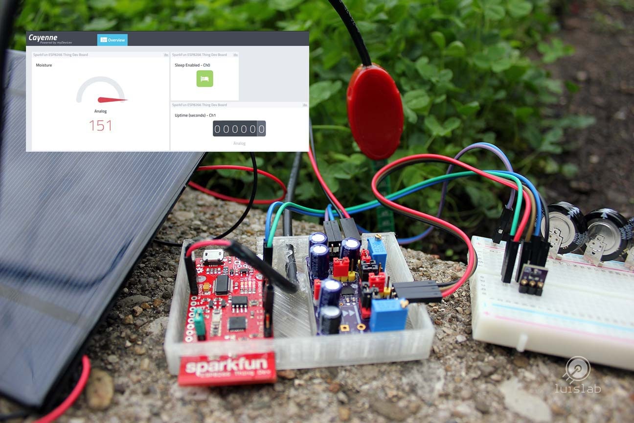
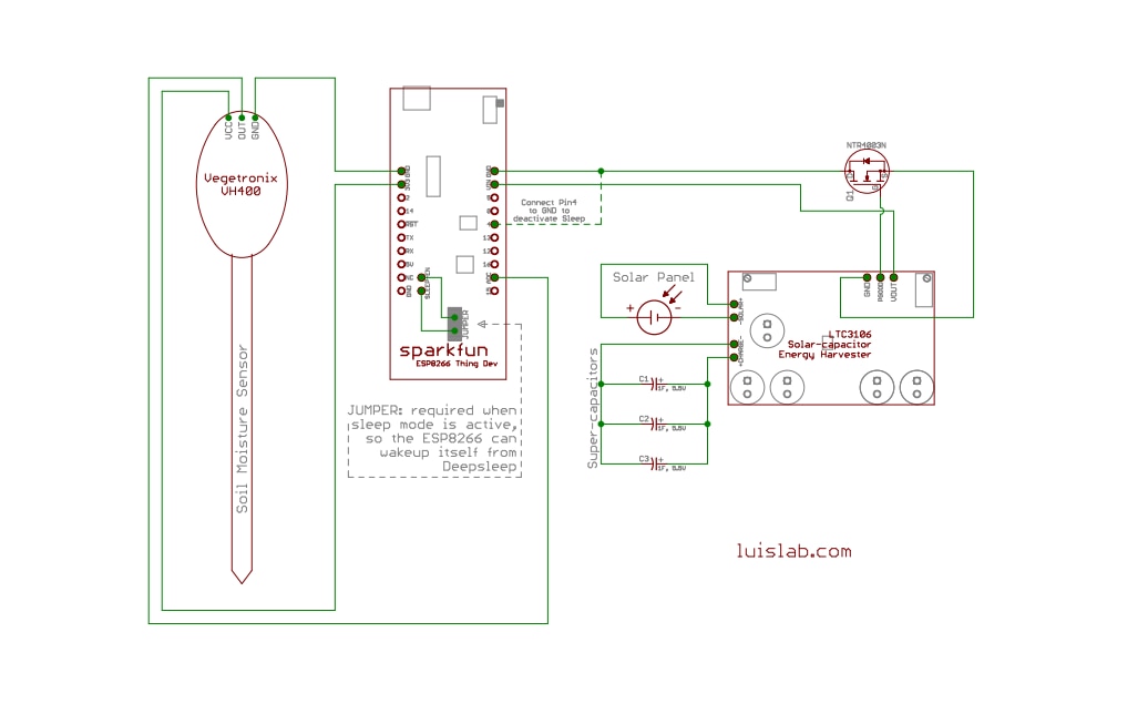
The Solar powered IoT device illustrates a concept: harvesting energy from a solar panel by storing it in a rechargeable battery or super-capacitor and then using it to power a sensor connected to an IoT cloud provider.
Key elements of the Project
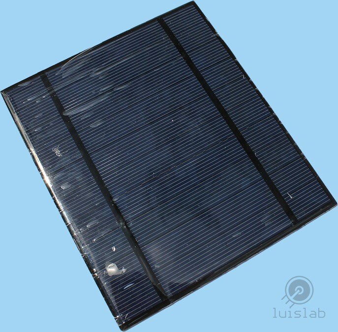
A solar panel
For this project, the energy harvester takes power from a 5V, 2.5W Solar panel.
Energy Harvester
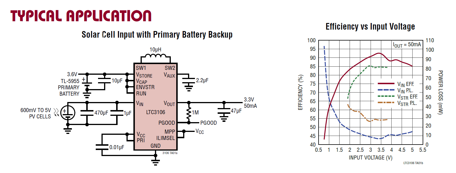
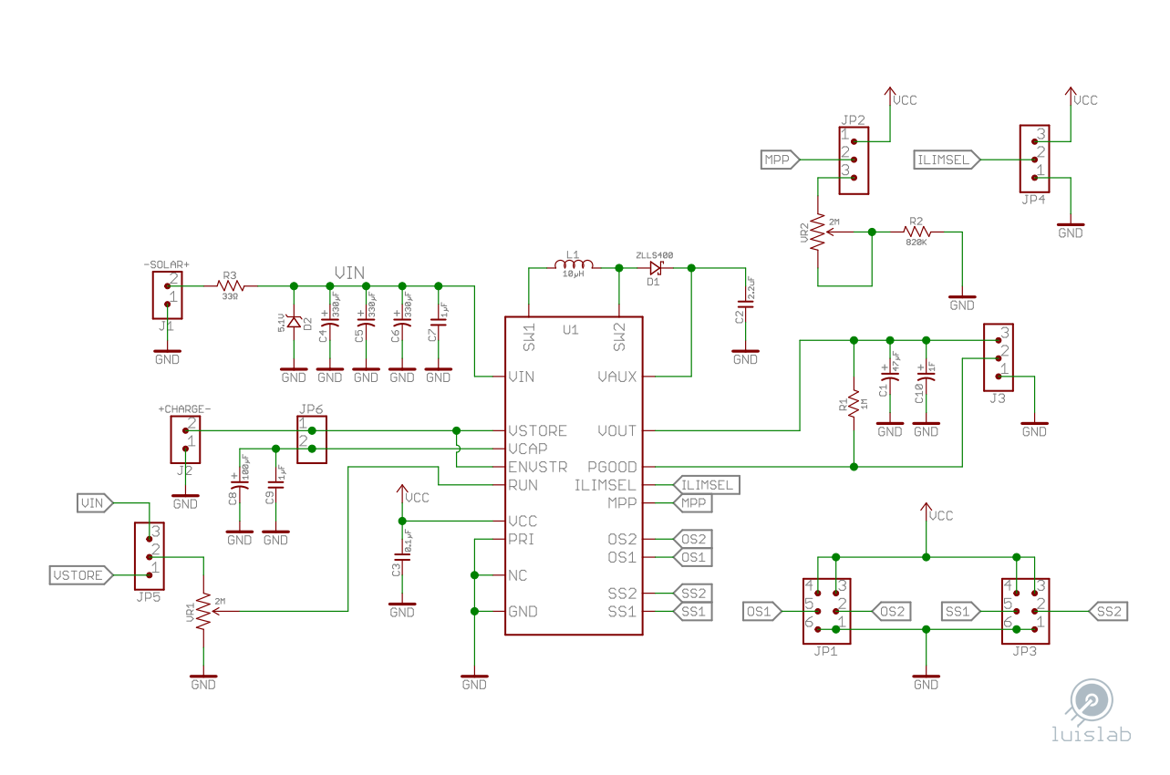
Will gather and store the energy provided by the solar panel. Driven by the LTC3106 from Linear TechnologyLTC3106 from Linear Technology, which is implemented in a custom made PCB, allowing some features of the chip to be programmed such as the output voltage (JP1), MPPC - Maximum Power Point Control (JP2 and VR2), Over/Under voltage threshold for the rechargeable backup battery (JP3), Low/High Current limit Input (JP4) and Input Turn On/Off thresholds (JP5 and VR1).

LTC3106's Features
These are the key features that made the LTC3106 a good choice for this project:
- Dual input: a primary and a backup source of power can be implemented
- Compatible with rechargeable batteries
- Low start-up voltage
- Regulated output
Backup battery
Excess input energy will be stored in one or more 1F, 5.5V radial super-capacitors1F, 5.5V radial super-capacitors for this particular scenario.

IoT sensor
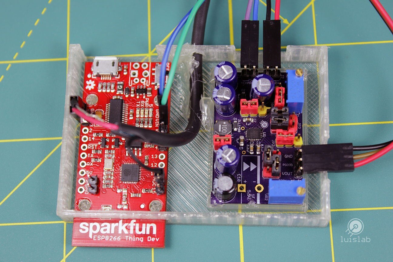
The SparkFun ESP8266 Thing - Dev Board provides IoT connectivity to a Vegetronix VH400 Soil moisture Sensor.
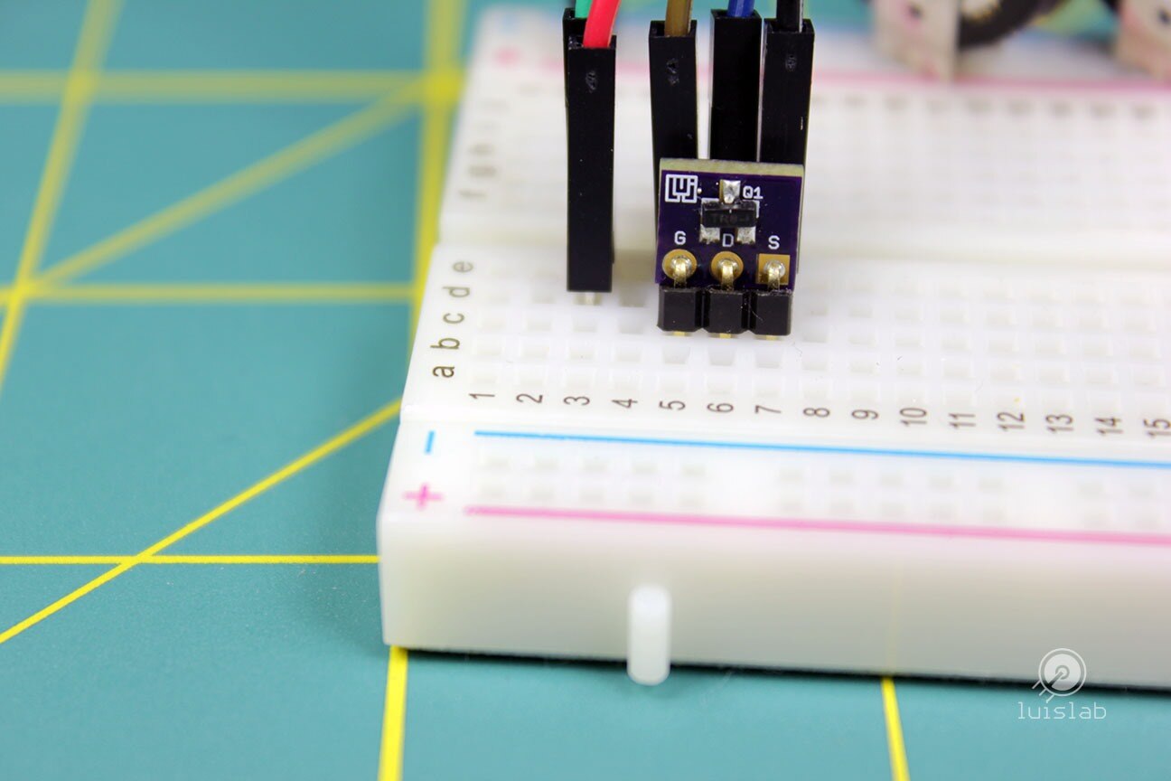
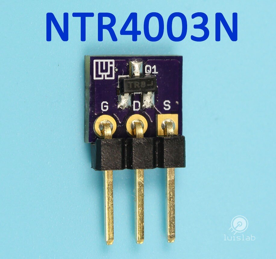
Mosfet
A NTR4003N N-Channel mosfetNTR4003N N-Channel mosfet (Q1) will be driving the power from the energy harvester to the IoT device once the output threshold has been reached.
| {gallery:width=648,height=432,autoplay=false} NTR4003 N-Channel mosfet |
|---|
NTR4003N: N-Channel Mosfet |
NTR4003N: Testing the Load with LEDs |
NTR4003N: N-Channel, 560 mA, 30 V, 1.5 ohm Mosfet |

Cayenne Software
The Cayenne software is used to monitor the data collected by the sensor (Ch4), the ESP8266's sleep setup (Ch0) and up-time (Ch1) -when sleep mode is not enabled-.

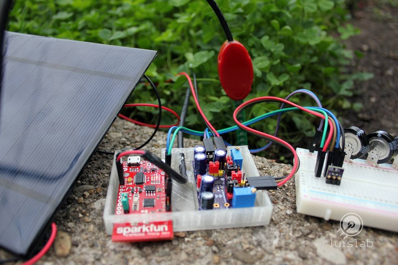
Assembly
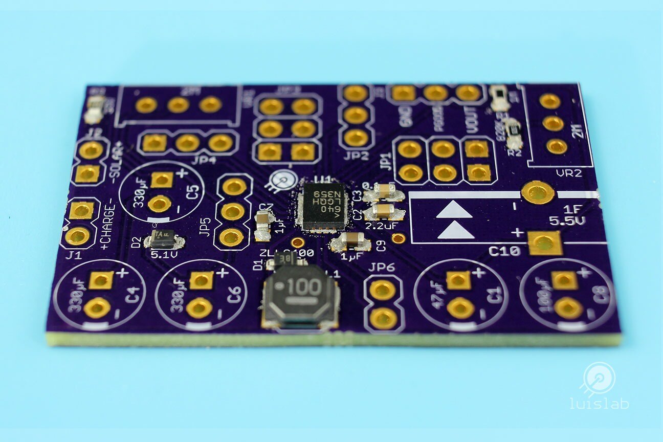
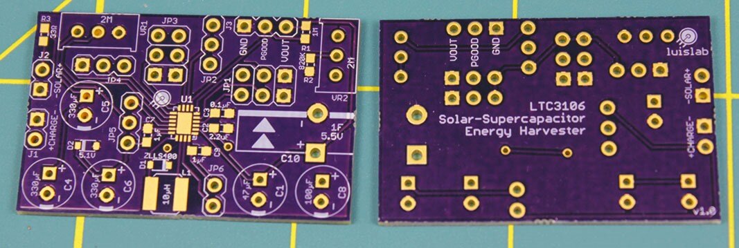
The energy harvester (custom PCB)
Most of the components of the custom PCB are SMD (I used the LTC3106 in QNF-20 package which was available at the time I started working on this project).
| {gallery:width=648,height=432,autoplay=false} Energy Harvester custom PCB |
|---|
Energy Harvester PCB: LTC3106 Energy Harvester PCB ready for hot-air rework |
PCB: Energy Harvester |
PCB: Energy Harvester |

BOM
- C1, C4, C5, C6: 330μF, 6.3V radial electrolytic capacitor (6.3mm diameter, through-hole)
- C2: 2.2µF, 10V ceramic Capacitor, 0603[1608]
- C3: 0.1μF, 6.3V ceramic capacitor 0603[1608]
- C7, C9: 1μF, 16V ceramic capacitor 0603[1608]
- C8: 100μF, 10V radial electrolytic capacitor (6.3mm diameter, through-hole)
- R1: 1Mohm, 1/10W, 1% resistor 0603[1608]
- R2: 820kohm resistor 0603[1608]
- R3: 33ohm resistor 0603[1608]
- VR1, VR2: 2Mohm trimmer potentiometer, through-hole
- D1: Schottky Diode ZLLS400ZLLS400 SOD-323
- D2: Zener Diode 5.1V SOD-323
- JP1, JP3: 2x3 through-hole header (2.54mm pitch)
- J3, JP2, JP4, JP5: 1x3 through-hole header (2.54mm pitch)
- J1, J2, JP6: 1x2 through-hole header (2.54mm pitch)
- L1: 10µH, minimum saturation current 750mA
- U1: Linear Technology LTC3106 (QFN-20)
- 2.54mm pitch, 2 position jumperstic.
Schematics
Wi-Fi Module
A 2-pin male header is required for the JUMPER_EN on the SparkFun ESP8266 Thing - Dev Board, this way it can wake up by itself from deep sleep mode -it will "sleep" for an interval of time defined in the source code-, headers may be soldered to connect the sensor(s).
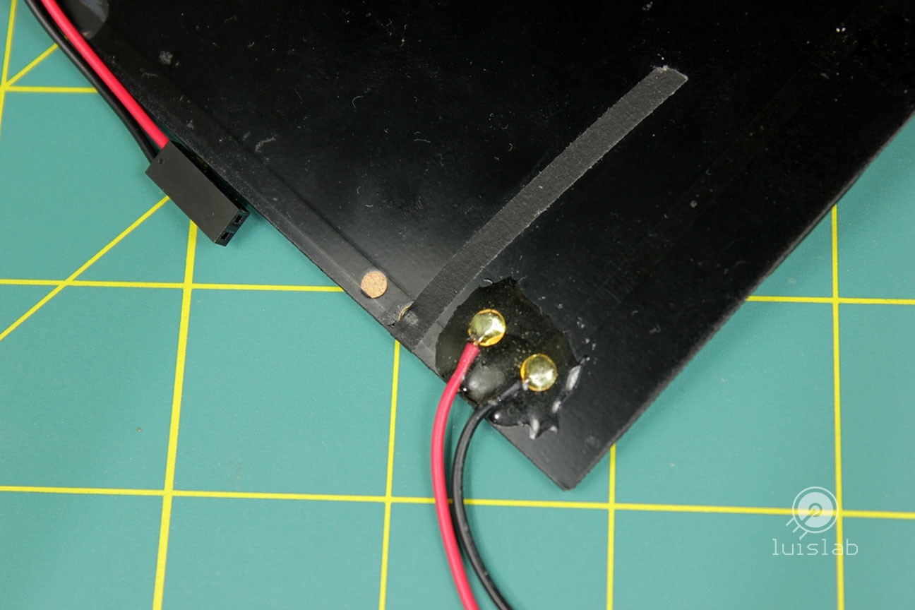
Solar Panel
The Solar panel requires wires to be soldered. I recommend to isolate their connections from the elements with some epoxy.
Main Schematic
Once the soldering job has been completed and all the components are ready, all the modules are assembled together with jumper wires following the main schematics.
Source Code
Source code for the ESP8266. Will push the sensor's data to the Cayenne Dashboard and will manage the deep sleep cycle (when active).
// Code for the IoT Energy Harvester
//
// Luis Ortiz - luislab.com
// October 4, 2017
// This sketch will publish analog sensor readings, uptime and DeepSleep status (Enabled/Disabled) to the Cayenne dashboard
//
// When deep sleep is enabled, set a jumper on the SLEEP-EN of the Sparkfun ESP8266 - Dev Board
// To upload the sketch. Jumper must be removed from the SLEEP-EN.

//#define CAYENNE_DEBUG
#define CAYENNE_PRINT Serial       // Comment this out to disable prints and save space
#define SLEEP_ENABLE_PIN 4         // Pin to manually Enable/Disable Deep Sleep.
#include <CayenneMQTTESP8266.h>

RF_MODE(RF_NO_CAL)

// WiFi network info.
char ssid[] = "ssid";
char wifiPassword[] = "wifiPassword";

// Cayenne authentication info. This should be obtained from the Cayenne Dashboard.
char username[] = "Cayenne-username";
char password[] = "Cayenne-password";
char clientID[] = "Cayenne-clientID";

unsigned long lastMillis = 0;

// To enable deep sleep: SLEEP_ENABLE_PIN is high or left disconnected -INPUT_PULLUP-. Jumper is required on SLEEP-EN
// To disable deep sleep: connect SLEEP_ENABLE_PIN to GND. Jumper is not required on SLEEP-EN.
const int sleepTimeS = 60;    //Publish interval or sleep time in seconds. See comments above

byte sleepEnabled;

void setup() {
  Serial.begin(9600);

  pinMode(SLEEP_ENABLE_PIN, INPUT_PULLUP);
  pinMode(BUILTIN_LED, OUTPUT);
  digitalWrite(BUILTIN_LED, HIGH);            //Led Off

  //Add static IP to reduce the WiFi startup time -reduces WiFi startup time, lowering power consumption-
  Cayenne.begin(username, password, clientID, ssid, wifiPassword);
}

void loop() {
  Cayenne.loop();

  sleepEnabled = digitalRead(SLEEP_ENABLE_PIN);
  if (sleepEnabled == LOW) {
    if (millis() - lastMillis > 10000) {
      lastMillis = millis();

      //Write data to Cayenne here.
      cayenneSendData();
    }
  } else {
    cayenneSendData();
    Serial.print("[LuisLab] deepSleep: "); Serial.print(sleepTimeS); Serial.println(" seconds.");
    Serial.println();
    delay(100);
    ESP.deepSleep(sleepTimeS * 1000000, WAKE_RF_DEFAULT);
  }
}

unsigned int Ch4Value;

void cayenneSendData () {
  Ch4Value = analogRead(A0);

  Cayenne.virtualWrite(0, sleepEnabled, "digital_sensor", "d");         //Sends sleepEnable status to button on Dashboard
  Cayenne.virtualWrite(1, round(lastMillis / 1000), "counter", "null"); //Sends the current uptime in milliseconds.
  Cayenne.virtualWrite(4, Ch4Value);
  if (sleepEnabled == LOW) {
    digitalWrite(BUILTIN_LED, LOW);     //Led will be On when Deep Sleep disabled
    Serial.println("[LuisLab] Ch0: Deep Sleep disabled");
  }
  Serial.print("[LuisLab] Ch4: "); Serial.println(Ch4Value);
  Serial.println();
}

//Default function for processing actuator commands from the Cayenne Dashboard.
//You can also use functions for specific channels, e.g CAYENNE_IN(1) for channel 1 commands.
CAYENNE_IN_DEFAULT() {
  CAYENNE_LOG("CAYENNE_IN_DEFAULT(%u) - %s, %s", request.channel, getValue.getId(), getValue.asString());
  //Process message here. If there is an error set an error message using getValue.setError(), e.g getValue.setError("Error message");
}
3D Printed Mount
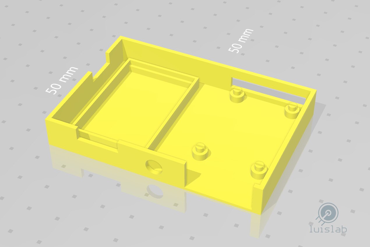
Mount is straight simple with slots for the custom PCB and for the Sparkfun ESP8266 Thing with space for the sensor wire routing. STL attached to this entry.
| {gallery:width=648,height=432,autoplay=false} 3D printed mount |
|---|
Enclosure: IoT Energy Harvester 3D-printed enclosure |
STL: IoT Energy Harvester 3D enclosure design |

3D print settings
- Printer: Lulzbot Mini
- Material: PLA Translucent
- Infill: 15%, grid
- Adhesion: Skirt
- Supports: No
- Layer height: 0.2mm
LTC3106 custom PCB settings
As mentioned before, I designed a custom PCB for the LTC3106 (QFN-20) allowing its key features to be programmed by adjusting some Jumpers, the Potentiometers (VR1 and VR2) and the value of R2.

For this project, the following settings were used:
- Output voltage to 3.3V (JP1).
- MPPC disabled (JP2) -this will ignore VR2 and R2-.
- Battery Over Voltage to 4V and Under Voltage (UV) to 2.78V (JP3)
- On/Off threshold on VIN (JP5)
- On/Off threshold set to 2.95V (VR1)
- To properly test the energy harvester: the load and the SOLAR input are connected and once the Super-capacitors are fully charged -their voltage matches the Over Voltage threshold programmed (JP2)- the SOLAR input can be disconnected; the load connected to the VOUT should keep working for a brief period.
JP1 – Programmable output voltage (VOUT)

JP2 – Maximum Power Point Control (MPPC)
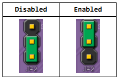
When the MPPC is enabled, it sets the optimal input voltage operating point by adjusting VR2 (VR2 is configured as a variable resistor with R2 in series):
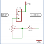
To set a precise resistance value for MPP, the jumper JP2 must be removed, then adjust the VR2 value by measuring its resistance between the CCW/Input Pin (top-right corner in the PCB) and the Wiper/Output Pin (middle), then add the R2 value.
JP3 – Battery backup Over/Under voltage threshold
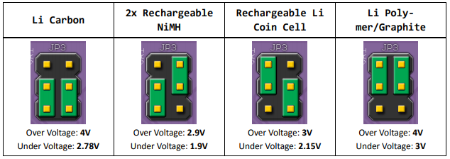
The custom PCB for this project was designed to connect rechargeable batteries only to VSTORE (J1). To use a super-capacitor as a backup battery, the most suitable Over Voltage (OV), Under Voltage (UV) setting should be used.
JP4 – Current limit input select (ILIMSEL)
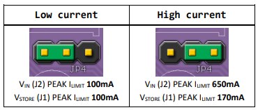
JP5 – Input Turn ON/OFF Thresholds (RUN)
JP5 programs a predictable regulator turn-on at a specified input voltage by adjusting VR1 (acting as a voltage divider).
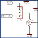
To set a precise resistance value for VR1, jumpers JP4 and JP5 must be removed then the divider value is adjusted by measuring its resistance (CW/Ground pin of the divider is the closest to JP3 in the PCB):
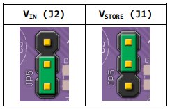
- VIN (J2): sets the turn ON/OFF threshold from the solar input VIN (J2)
- VSTORE (J1) : sets the turn ON/OFF threshold from the input VSTORE (J1)
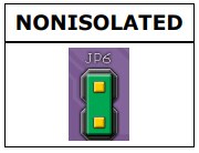
JP6 – Isolation mode (VSTORE/VCAP)
The PCB was designed to work in NONISOLATED mode only; a jumper must be present on JP6 at all times.
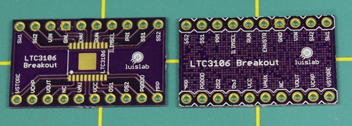
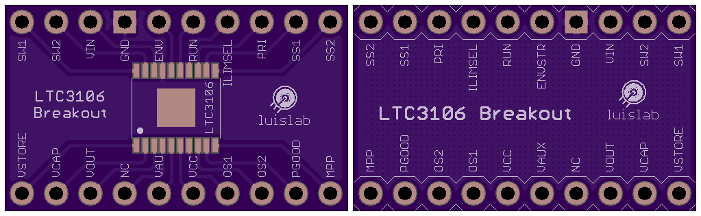
A more friendly approach (Breakout)
If you are feeling that you are not ready for an QFN-20 SMD challenge and/or want to approach this project with a Breadboard instead, I'm also providing a breakout for the LTC3106 in its TSSOP-20 version.
| {gallery:width=648,height=432,autoplay=false} LTC3106 Breakout |
|---|
LTC3106 Breakout: LTC3106 Breakout TSSOP-20 |
LTC3106 Breakout: LTC3106 Breakout TSSOP-20 |
How this project can be improved
This project is far from perfect for every single situation out there but illustrates a powerful concept that can be expanded on other projects. For demonstration purposes, I've decided to store the excess energy into super-capacitors but rechargeable batteries is ideal: JP3 should be enabled accordingly.
Bypassing the voltage regulator and the FTDI chip of the ESP8266 Thing - Dev Board may improve power consumption since the LTC3106 already has a 3.3V regulated output (JP1).
Using static IP is the best practice since this takes only a fraction of a second; when using DHCP the WiFi connection takes a longer startup time and thus consumes more power.
Thanks for reading along.
Luis
| IoT solar harvester main schematic.pdf | |

Top Comments