


I was building a big project and wanted to move the nozzle of a squirting flower, and the only servos I had were micro servos which did not have enough power to move the mechanism, so I decided to build something, a Jumbo Servo.

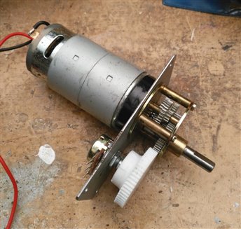
As mentioned in Motor Drive Control for Makers a servo consists of a motor with some kind of position feedback and a control circuit. I decided that a potentiometer and an arduino should be capable of this. I found a 12v gearbox motor in the spares drawer and after a little cleaning and lubrication got that running. There was a gear on the output shaft that could be used for driving a the potentiometer. I added a mounting plate and determined where I could add a potentiometer. A 3D printed gear was added to slip onto the pot and mesh with the output gear. Also something to drive the motor would be needed and I had a suitable L298 H-Bridge module which fitted the spec.
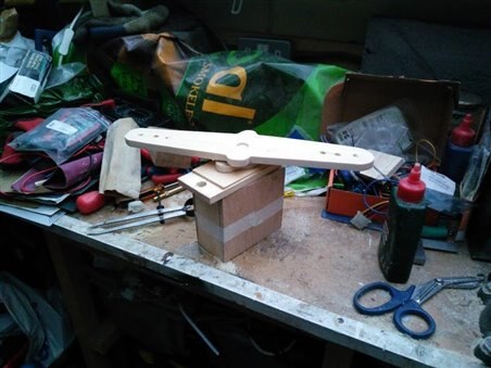
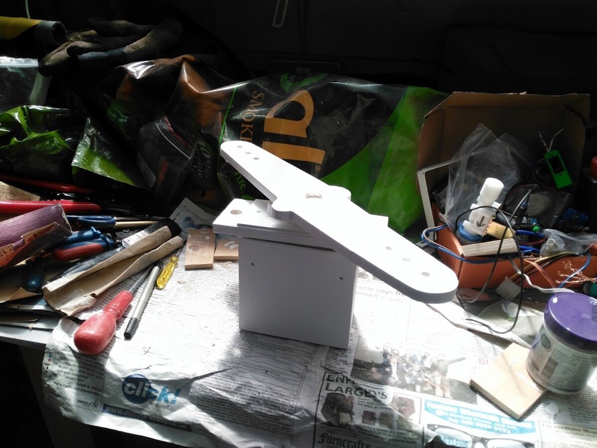
So that my jumbo servo would look the part, I made a wooden case and wooden servo horn. A 3D printed output shaft was also added.

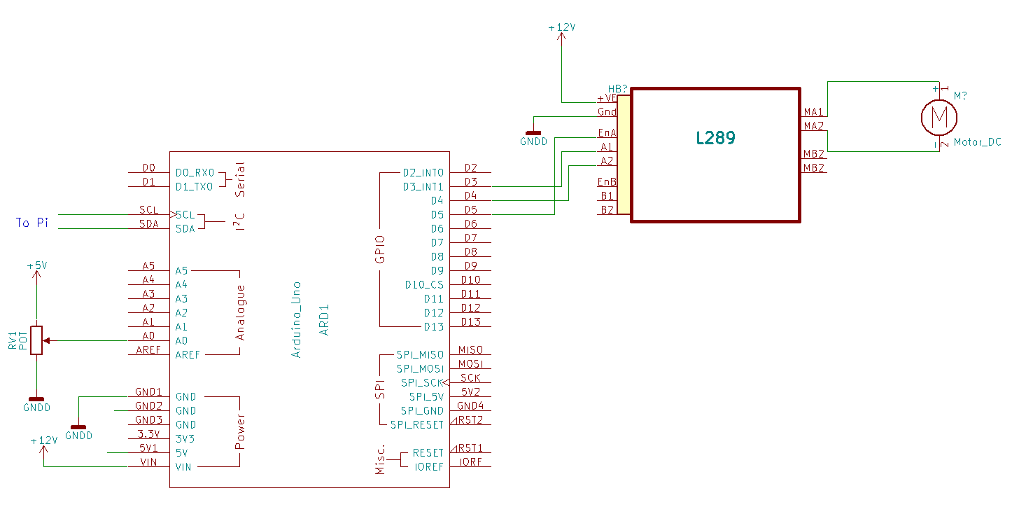
Next up was the electronics. I decided to go with I2C for communication rather than the analogue PWM which is typically used by a servo. This allows me to stop the motor when the servo has reached it's destination rather than constantly seeking position, it also means that I can read back the position to the controlling software and avoid that twitch you get when you first power on a servo.
To test this I used two arduinos and used the examples from Arduino to work out what code was needed. Because I was using a long cable (for I2C at least) I added some low value pullups on the servo end.

Here's my first draft of the code.
#include <Wire.h>

const int slaveAddress = 8;

const int sensePin = A0;
const int drivePin1 = 3;
const int drivePin2 = 4;
const int speedPin = 5; //Needs to support PWM

short registers[5];
int readCmd;
int blink = 0;

enum readRegisters { Target = 0,
  Running = 1,
  Position = 2,
  Speed = 3,
  Direction = 4
  };

enum commands { CmdStop = 1,
  CmdAngle = 2,
  CmdSpeed = 3,
  };

void setup() {
  stop();

  pinMode(drivePin1, OUTPUT);
  pinMode(drivePin2, OUTPUT);
  pinMode(speedPin, OUTPUT);
  pinMode(13, OUTPUT); //Onboard LED
  pinMode(sensePin, INPUT);

  Wire.begin(slaveAddress); // join i2c bus with address #8
  Wire.onReceive(receiveEvent); // write data
  Wire.onRequest(requestEvent); // requests to read data

}

void loop() {
  digitalWrite(13, blink);
  blink = !blink;

  registers[Position] = analogRead(sensePin);

  if (registers[Running]) {
       if (registers[Direction] == 1) {
            if (registers[Position] >= registers[Target]) {
                 stop();
            }
       }
       if (registers[Direction] == -1) {
            if (registers[Position] <= registers[Target]) {
                 stop();
            }
       }
  }
}

void stop() {
  digitalWrite(drivePin1, LOW);
  digitalWrite(drivePin2, LOW);
  analogWrite(speedPin, 0);
  registers[Running] = false;
}

// function that executes whenever data is received from master
// this function is registered as an event, see setup()
void receiveEvent(int bytesReceived) {
  char command;
  int value;
  int lowB;
  int highB;

  switch (bytesReceived) {
  case 1:
  //Read request register
  readCmd = Wire.read();
  break;
  case 3:
       command = Wire.read(); // receive byte as a character
       //Pi is low endian
       lowB = Wire.read();
       highB = Wire.read();
       value = (highB << 8) | lowB;

       switch (command) {
       case CmdStop:
            stop();
            break;
       case CmdAngle:
            registers[Target] = value;
            registers[Running] = true;
            if (registers[Target] > registers[Position]) {
                 digitalWrite(drivePin1, LOW);
                 digitalWrite(drivePin2, HIGH);
                 registers[Direction] = 1;
            }
            else {
                 digitalWrite(drivePin2, LOW);
                 digitalWrite(drivePin1, HIGH);
                 registers[Direction] = -1;
            }
       break;
       case CmdSpeed:
            registers[Speed] = value;
            analogWrite(speedPin, registers[Speed]);
       break;
       }
  break;
  default:
       for (int a = 0; a < bytesReceived; a++) {
            Wire.read(); // throw buffer away so we can read again
       }
  }
}

// function that executes whenever data is requested by master
// this function is registered as an event, see setup()
// Don't add serial print to this routine, it will error!!

void requestEvent() {

  short value = registers[readCmd];
  Wire.write((uint8_t *)&value, sizeof(value));
}
I've got myself an AdaFruit "ItsyBitsy" which is basically a small form factor Arduino Leonado. So the next step is to wire this in, instead of the Arduino.
I'll also need to do some simple calibration to turn the 0-1023 value into a degrees value. Because of the gearing on the pot the servo can do a bit more than 180 degress so I should be able to set it up with a safe limit so I don't over drive the pot.
Have added a breakout board for the ItsyBity and completed some further testing with some LEDs in place of the H-Bridge,


I then did some testing with the H-Bridge. I used back to back LEDs to check that the circuit was wired correctly and the software was working. After a few loose connections I got that working. However, swapping the motor in caused my 2A PSU to shutdown.
So I plugged these into the bench power supply (thanks again Secret Santa) and set the voltage and current limit. Luckily I happened to have a slightly smaller motor that had the same size shaft and screw holes that took a lot less current. Next up I'll swap that in.
The gearbox I used is available on CPC.
Top Comments