element14 Community
element14 Community
    Register Log In
  • Site
  • Search
  • Log In Register
  • About Us
  • Community Hub
    Community Hub
    • What's New on element14
    • Feedback and Support
    • Benefits of Membership
    • Personal Blogs
    • Members Area
    • Achievement Levels
  • Learn
    Learn
    • Ask an Expert
    • eBooks
    • element14 presents
    • Learning Center
    • Tech Spotlight
    • STEM Academy
    • Webinars, Training and Events
    • Learning Groups
  • Technologies
    Technologies
    • 3D Printing
    • FPGA
    • Industrial Automation
    • Internet of Things
    • Power & Energy
    • Sensors
    • Technology Groups
  • Challenges & Projects
    Challenges & Projects
    • Design Challenges
    • element14 presents Projects
    • Project14
    • Arduino Projects
    • Raspberry Pi Projects
    • Project Groups
  • Products
    Products
    • Arduino
    • Avnet Boards Community
    • Dev Tools
    • Manufacturers
    • Multicomp Pro
    • Product Groups
    • Raspberry Pi
    • RoadTests & Reviews
  • Store
    Store
    • Visit Your Store
    • Choose another store...
      • Europe
      •  Austria (German)
      •  Belgium (Dutch, French)
      •  Bulgaria (Bulgarian)
      •  Czech Republic (Czech)
      •  Denmark (Danish)
      •  Estonia (Estonian)
      •  Finland (Finnish)
      •  France (French)
      •  Germany (German)
      •  Hungary (Hungarian)
      •  Ireland
      •  Israel
      •  Italy (Italian)
      •  Latvia (Latvian)
      •  
      •  Lithuania (Lithuanian)
      •  Netherlands (Dutch)
      •  Norway (Norwegian)
      •  Poland (Polish)
      •  Portugal (Portuguese)
      •  Romania (Romanian)
      •  Russia (Russian)
      •  Slovakia (Slovak)
      •  Slovenia (Slovenian)
      •  Spain (Spanish)
      •  Sweden (Swedish)
      •  Switzerland(German, French)
      •  Turkey (Turkish)
      •  United Kingdom
      • Asia Pacific
      •  Australia
      •  China
      •  Hong Kong
      •  India
      •  Korea (Korean)
      •  Malaysia
      •  New Zealand
      •  Philippines
      •  Singapore
      •  Taiwan
      •  Thailand (Thai)
      • Americas
      •  Brazil (Portuguese)
      •  Canada
      •  Mexico (Spanish)
      •  United States
      Can't find the country/region you're looking for? Visit our export site or find a local distributor.
  • Translate
  • Profile
  • Settings
Music Time
  • Challenges & Projects
  • Project14
  • Music Time
  • More
  • Cancel
Music Time
P14 Music Time Blog Multi-Voice Synthesizer - Part 5 - Let's Make Some Noise.
  • Blog
  • Forum
  • Documents
  • Events
  • Polls
  • Files
  • Members
  • Mentions
  • Sub-Groups
  • Tags
  • More
  • Cancel
  • New
Join Music Time to participate - click to join for free!
  • Share
  • More
  • Cancel
Group Actions
  • Group RSS
  • More
  • Cancel
Engagement
  • Author Author: genebren
  • Date Created: 26 Mar 2023 7:32 PM Date Created
  • Views 1691 views
  • Likes 9 likes
  • Comments 2 comments
  • musictimech
  • noise
Related
Recommended

Multi-Voice Synthesizer - Part 5 - Let's Make Some Noise.

genebren
genebren
26 Mar 2023

In my prior blog (  Multi-Voice Synthesizer - Part 4 - New schematics and layouts.  )  I covered the latest designs for my Multi-Voice Synthesizer project. Today, I am going to make a little Noise.

Going into this project, one of my goals was to use the Voice Module to generate musical notes and to also generate some noise.  I have achieved that goal by porting and modifying my noise source from my Op-Amp-a-Palooza project (  Adding additional capabilities to my KORG volca modular synthesizer and learning about Op-Amps at the same time. )  to work with my current Voice Module.

The normal Voice Processor firmware uses a fixed timer interrupt (10 µS or 100 kHz) to update the DAC and compute the waveform value for the next interrupt.  Replacing the waveform look up code with the noise processing code will allow me to convert a Voice Module into a Noise Module. The ATTiny1614 processor, in its Timer Interrupt uses a Linear Feedback Shift Register (LFSR) technique, using a 40 bit register length to develop a Pseudo Random bit sequence. Here is a logical diagram of the LFSR implementation that I utilized:

image

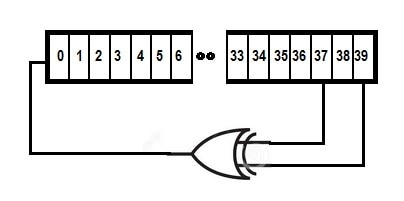
The LFSR register was made up of 5 8-bit words (declared as unsigned char) that were assigned by the compiler to registers so that they did not need to be read/stored into memory. During each Timer interrupt, the most significant 8 bits are written to the DAC output register. The LFSR was declared as follows (along with a temporary register to assist in the computations):

register unsigned char LFSR1;
register unsigned char LFSR2;
register unsigned char LFSR3;
register unsigned char LFSR4;
register unsigned char LFSR5;
register unsigned char TEMP;

Theses registers were initialized with random values during the 'setup' portion of the 'C' code:

    LFSR1 = (unsigned char) rand();
    LFSR2 = (unsigned char) rand();
    LFSR3 = (unsigned char) rand();
    LFSR4 = (unsigned char) rand();
    LFSR5 = (unsigned char) rand();
    TEMP = 0;

The compiler then assigned these variables to register during the compilation process.  Here are the resulting assignments:

                 ;NAME DEFINITIONS FOR GLOBAL VARIABLES ALLOCATED TO REGISTERS
                     .DEF _LFSR1=R3
                     .DEF _LFSR2=R2
                     .DEF _LFSR3=R5
                     .DEF _LFSR4=R4
                     .DEF _LFSR5=R7
                     .DEF _TEMP=R6

Here is the assembly language code that I had developed to process the LFSR function.

    DAC0.DATA = LFSR5;
#asm
    ;Generate the feedback from bits 39,35 (NOTE! Hill uses 1,2,3,4 numbering)
    clr     R6          ;TEMP = 0
    sbrc    R7,6        ;test b39
    inc     R6          ;ITEMP
    sbrc    R7,2        ;test b35
    inc     R6          ;ITEMP2
    ror     R6          ;put bit 0 into carry
    ;Shift everyone over, and the carry into the register.
                        ;Bits   Hill's bits
    rol		R3  		;7-0     8-1
    rol		R2  		;15-8    16-9
    rol 	R5  		;23-16   and so on
    rol		R4  		;31-17
    rol		R7  		;39-32   40-33
#endasm    

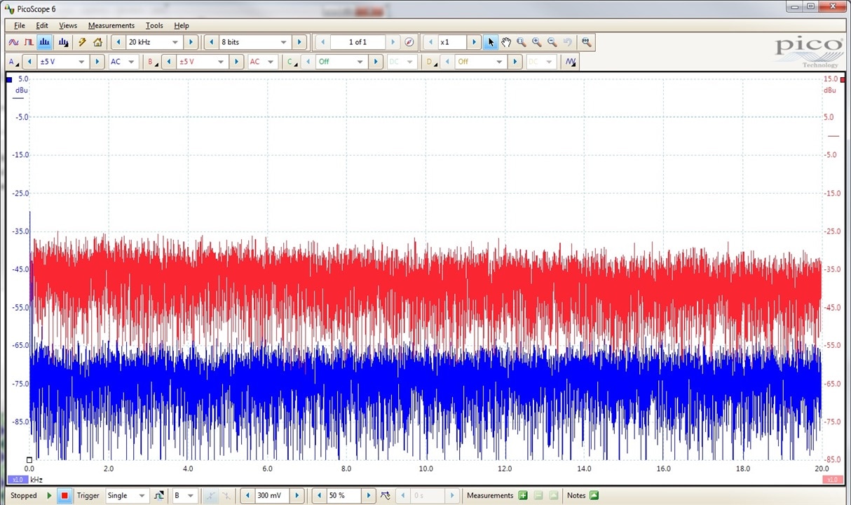
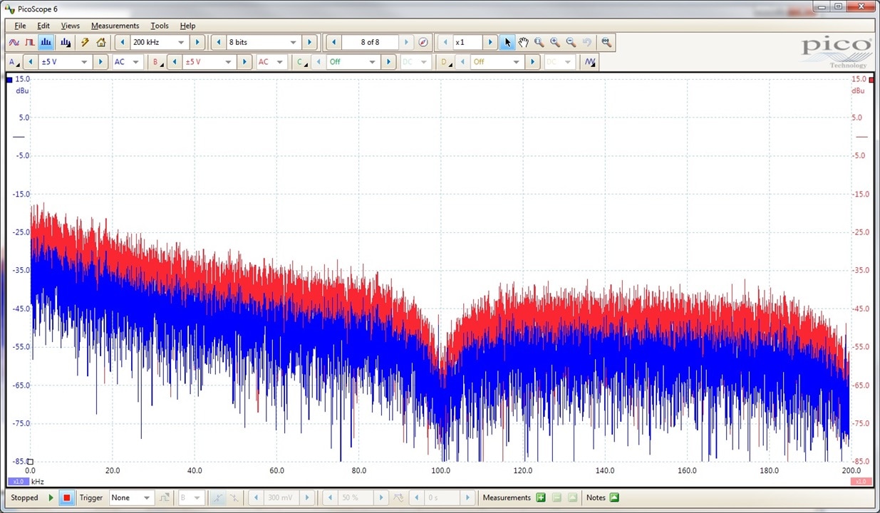
In the future, I might want to change the interrupt rates in order to generate even higher frequencies into the noise (closer to the maximum DAC update rate of 350 kHz), but for now it looks pretty good. Here is a capture of the noise spectrum, taken at the DAC output (red) and from the Echo Circuit output (bypassed - blue).  There is a DC shift and some gain variations between these two measurements, but the flat spectrum shows that we have a pretty flat, wide band noise output.

image

Looking deeper at the noise output, you can see the 100 kHz update rate:

image

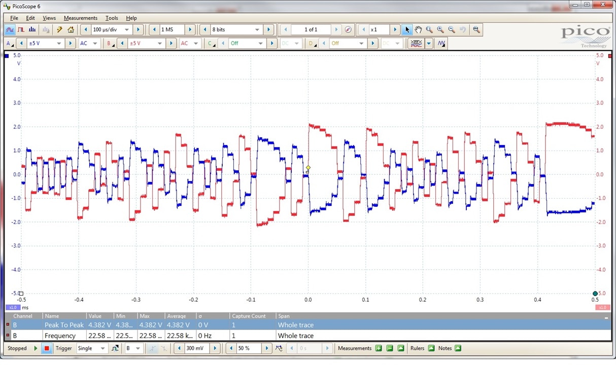
Here is a capture of the noise output, again taken at the DAC output (red) and from the Echo Circuit output (bypassed - blue). The Echo output is inverted due to the inverting summing circuit that combine the outputs from the multiple (up to 6) Voice Modules.  It is interesting to see the different patterns that work through the noise waveforms, from single bit toggles to lower frequency artifacts as the upper 8-bits transition from all '1's to all '0's, one bit at a time.

As an added 'effect', the summing circuit has a gain adjustment that can be set such that the noise output saturates (clips) which tends to lower the frequency component.  Here are a capture of the 'clipped' waveform and side by side spectrum of the noise (first low gain, then high gain).

image

image

image

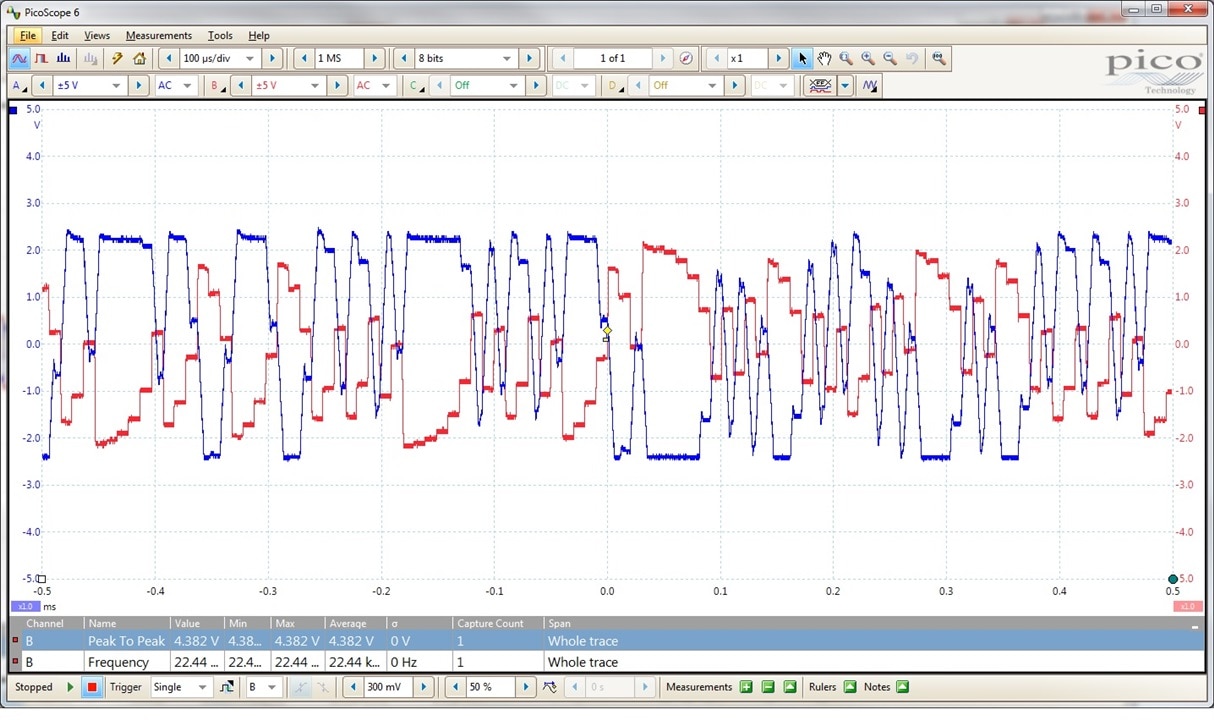
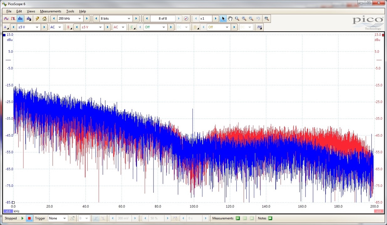
The added gain increase the overall noise below the sampling rate (100 kHz), but decrease the noise above 100 kHz.

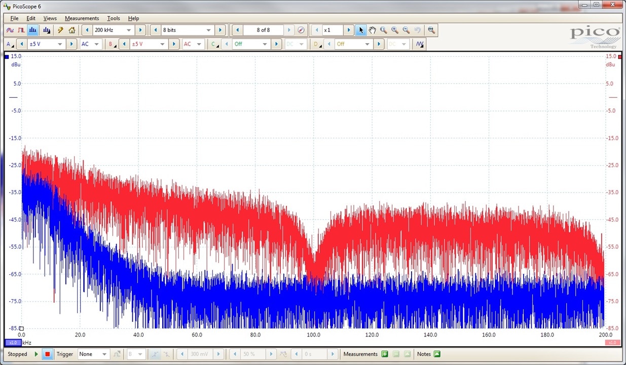
Switch in the Echo processor, also has an effect on the Noise spectrum.  The filters in both the Modulator and Demodulator of the Noise processor are attenuating the higher frequencies (above 10 kHz) resulting in a rolloff in the spectrum (down 40 dBu at 40 kHz):

image

To give you an idea of the sounds of the generate a noise I created a short video of the setup while changing settings on the control panel.  Warning some of the audio (speaking) gets overrun by the noise.

https://youtu.be/ReGgkfnMK8s

  • Sign in to reply
  • genebren
    genebren over 2 years ago in reply to javagoza

    Thanks!  Yes, it should be very easy to generate noise with an FPGA.  I look forward to reading more of your FPGA blogs!

    • Cancel
    • Vote Up 0 Vote Down
    • Sign in to reply
    • More
    • Cancel
  • javagoza
    javagoza over 2 years ago

    Oh! another thing i have to try. It seems easy to generate that white noise with an FPGA. Thank you, it is being very entertaining to follow your project, good progress.

    • Cancel
    • Vote Up 0 Vote Down
    • Sign in to reply
    • More
    • Cancel
element14 Community

element14 is the first online community specifically for engineers. Connect with your peers and get expert answers to your questions.

  • Members
  • Learn
  • Technologies
  • Challenges & Projects
  • Products
  • Store
  • About Us
  • Feedback & Support
  • FAQs
  • Terms of Use
  • Privacy Policy
  • Legal and Copyright Notices
  • Sitemap
  • Cookies

An Avnet Company © 2025 Premier Farnell Limited. All Rights Reserved.

Premier Farnell Ltd, registered in England and Wales (no 00876412), registered office: Farnell House, Forge Lane, Leeds LS12 2NE.

ICP 备案号 10220084.

Follow element14

  • X
  • Facebook
  • linkedin
  • YouTube