


In my prior Op-Amp-a-Palooza posts:
I described the steps of designing, building and testing my MIDI player for driving my KORG volca modular synthesizer. Today I am going to document the final steps and wrap up my submission to this contest. When I finished up the prior installment, I demonstrated the noise source coupled into the synthesizer. Since that posting, I have coded a simple MIDI player (I'll call it SMIDI), so that it is now possible to play a song (a series of singular notes, interspersed with control voltage changes). Before we get to the music, let's look into the connections between the SMIDI player and the KORG volca modular synthesizer. The synthesizer receives the following voltages from the SMIDI player:
- 9 Volt Power - The Synthesizer has a somewhat unique power input, so I am using a right angle adapter plug (2.1mm x 5.5mm male to a 1.7mm x 4.8mm female) to provide power. The SMIDI player has two 2.1mm x 5.5mm jacks one for power in and one for power transfer to the synthesizer. A short patch cable is used to provide power (via the adapter) to the synthesizer. I am using a 9V 1A DC power adapter to power both the SMIDI player and the synthesizer.
- Pitch/Gate CV-IN - The 6" 3.5mm stereo audio patch cable connects the SMIDI's Pitch and Gate control signals to the synthesizer. The 'tip' is used to send the GATE signal (0.0 to 3.3 volts) to indicate when the SMIDI player is "pressing" (High) or releasing (Low) a key, while the middle 'ring' is used to send the pitch signal (0.0 to 6.0 volts, 1 volt per octave) to indicate the note being played. The shield is used to tie the SMIDI and synthesizer grounds (even with the power applying ground). Once plugged into the synthesizer, these signals (Pitch and Gate) need to be routed to inputs on the synthesizer. I needed to create a splitter wire so that I could route the GATE signal into the main ATTACK/RELEASE envelope generator, as well as to the LVO/ENVELOPE function. The PITCH voltage drives the main SOURCE (oscillator) to generate the correct pitches.
- Control Voltages - A 20 lead ribbon cable is used to route 15 programmable DC voltage (CVs), a noise source and 4 I/O signals to the synthesizer. All of these signals can be controlled, via the SMIDI player and passed on to the synthesizer (the I/O are not implemented yet).
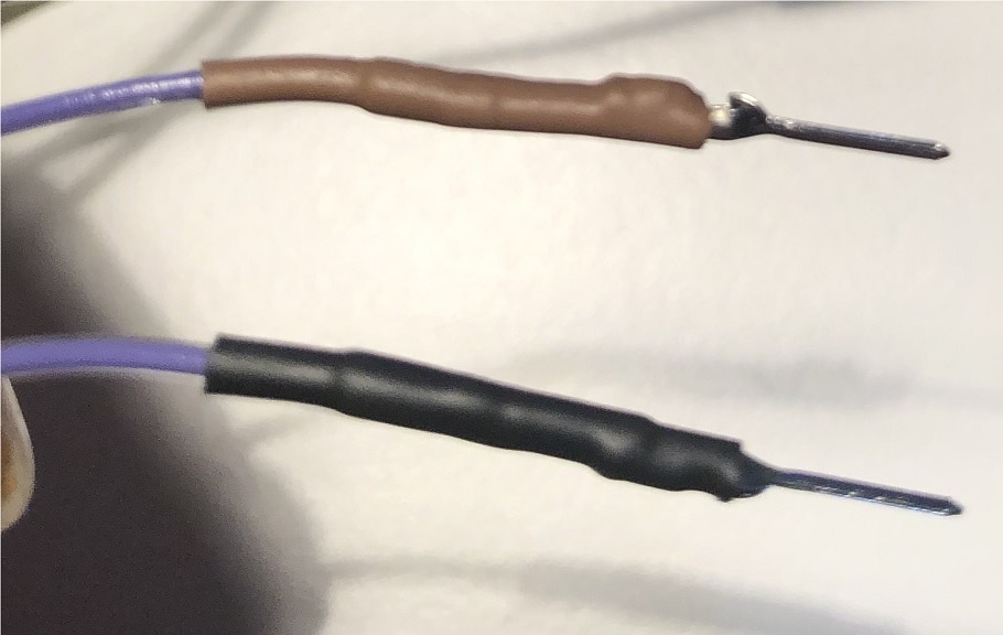
Instead of using off the shelf jumper wires, I created a bulk terminated ribbon cable that will plug into the SMIDI players 20-pin header (nice snug connection to the SMIDI board). The other ends of the ribbon are broken out into individual flying leads, with crimped on pins and covered with heat-shrink. To distinguish the same colored wires the first 10 leads are using Black heat-shrink, while the second ten leads are using Brown heat-shrink. I have to say, that today was a great crimping day! I did not have a single failure in the process, which is not my usual experience working with crimpers. Here is my completed cable:

Here is an image of the SMIDI connected to the synthesizer:

Software Functions
1 - Hardware Controls
Most of the control signals used to drive the synthesizer are analog levels, derived from DACs (or Digital Potentometers) which are all controller by I2C. Here are the low level control functions that are used to drive these DAC/Potentometers values:
void WritePitchValue(unsigned int PitchVal)
{
    TWI_out[0] = ((PitchVal >> 8) & 0x0F);
    TWI_out[1] = (PitchVal  & 0xFF);
    twi_master_trans(PITCH_DAC_ADDR, TWI_out, 2, NULL, 0);
}
void WriteDAC1Value(unsigned int Value, unsigned char Channel)
{
    TWI_out[0] = Channel << 3;
    TWI_out[1] = 0;
    TWI_out[2] = (Value  & 0xFF);
    twi_master_trans(DAC1_ADDR, TWI_out, 3, NULL, 0);
    DAC_LATCH = 0;
    DAC_LATCH = 1;
}

void WriteDAC2Value(unsigned int Value, unsigned char Channel)
{
    TWI_out[0] = Channel << 3;
    TWI_out[1] = 0;
    TWI_out[2] = (Value  & 0xFF);
    twi_master_trans(DAC2_ADDR, TWI_out, 3, NULL, 0);
    DAC_LATCH = 0;
    DAC_LATCH = 1;
}
void WriteDigPotValue(unsigned char Attenuation)
{
    TWI_out[0] = Attenuation;
    twi_master_trans(DIG_POT, TWI_out, 1, NULL, 0);
}
2 - SMIDI player
The Simplified MIDI player is a simple token directed file reader that interprets token and data into actions. This SMIDI player interprets Tempo, Key_Down, Key_Up, CV_Control, Noise_Select and End_Song tokens. The SMIDI file is currently hardcoded into the ATmega328PB RAM (initialized at power up) and started via the USB link. Here are the code fragments for the SMIDI player:
unsigned char MidiFile[256] = {
    0xf1, 0x00, 0x00,            // DAC1-0 0
    0xf1, 0x01, 0x00,            // DAC1-1 0
    0xf2, 0x01, 0x7f,            // White noise 50%
    0x80, 0x1f, 0x03, 0x90, 0x80, 0x1c, 0x03, 0x90, 0x80, 0x1f, 0x04, 0x90,                                                  // Bar 1 - GEG
    0x80, 0x1f, 0x03, 0x90, 0x80, 0x1c, 0x03, 0x90, 0x80, 0x1f, 0x04, 0x90,                                                  // Bar 2 - GEG
    0x80, 0x21, 0x03, 0x90, 0x80, 0x1f, 0x03, 0x90, 0x80, 0x1d, 0x03, 0x90, 0x80, 0x1c, 0x03, 0x90,                          // Bar 3 - AGFE
    0x80, 0x1a, 0x03, 0x90, 0x80, 0x1c, 0x03, 0x90, 0x80, 0x1d, 0x04, 0x90,                                                  // Bar 4 - DEF
    0x80, 0x1f, 0x03, 0x90, 0x80, 0x18, 0x03, 0x90, 0x80, 0x18, 0x02, 0x90, 0x80, 0x18, 0x02, 0x90, 0x80, 0x18, 0x03, 0x90,  // Bar 5 - GCCCC
    0x80, 0x18, 0x02, 0x90, 0x80, 0x1a, 0x02, 0x90, 0x80, 0x1c, 0x02, 0x90, 0x80, 0x1d, 0x02, 0x90, 0x80, 0x1f, 0x04, 0x90,  // Bar 6 - CDEFG
    0x80, 0x1f, 0x03, 0x90, 0x80, 0x1a, 0x03, 0x90, 0x80, 0x1a, 0x03, 0x90, 0x80, 0x1d, 0x03, 0x90,                          // Bar 7 - GDDF
    0x80, 0x1c, 0x03, 0x90, 0x80, 0x1a, 0x03, 0x90, 0x80, 0x18, 0x04, 0x90,                                                  // Bar 8 - EDC

    0xf1, 0x00, 0x7f,            // DAC1-0 0x7f
    0xf1, 0x01, 0x7f,            // DAC1-1 0x7f
    0x80, 0x1f, 0x03, 0x90, 0x80, 0x1c, 0x03, 0x90, 0x80, 0x1f, 0x04, 0x90,                                                  // Bar 9 - GEG
    0x80, 0x1f, 0x03, 0x90, 0x80, 0x1c, 0x03, 0x90, 0x80, 0x1f, 0x04, 0x90,                                                  // Bar 10 - GEG
    0x80, 0x21, 0x03, 0x90, 0x80, 0x1f, 0x03, 0x90, 0x80, 0x1d, 0x03, 0x90, 0x80, 0x1c, 0x03, 0x90,                          // Bar 11 - AGFE
    0x80, 0x1a, 0x03, 0x90, 0x80, 0x1c, 0x03, 0x90, 0x80, 0x1d, 0x04, 0x90,                                                  // Bar 12 - DEF
    0x80, 0x1f, 0x03, 0x90, 0x80, 0x18, 0x03, 0x90, 0x80, 0x18, 0x02, 0x90, 0x80, 0x18, 0x02, 0x90, 0x80, 0x18, 0x03, 0x90,  // Bar 13 - GCCCC
    0x80, 0x18, 0x02, 0x90, 0x80, 0x1a, 0x02, 0x90, 0x80, 0x1c, 0x02, 0x90, 0x80, 0x1d, 0x02, 0x90, 0x80, 0x1f, 0x04, 0x90,  // Bar 14 - CDEFG
    0x80, 0x1f, 0x03, 0x90, 0x80, 0x1a, 0x03, 0x90, 0x80, 0x1a, 0x03, 0x90, 0x80, 0x1d, 0x03, 0x90,                          // Bar 15 - GDDF
    0x80, 0x1c, 0x03, 0x90, 0x80, 0x1a, 0x03, 0x90, 0x80, 0x18, 0x04, 0x90,                                                  // Bar 16 - EDC
    0xff};
The SMIDI player read and takes action on the tokens in order to control the synthesizer to play the song. In the first line of the player file, the value 0xf1 is the 'CV_Control' token, with parameters 0x00 and 0x00. The parameters are interpreted as DAC channel and value. This token, depending on the channel data calls either WriteDAC1Value (0-7) or WriteDAC2Value (8-15), passing the value in order to take actions. In this example, DAC1 channel zero routed to the main SOURCEs FOLD CV input (FOLD is a type of distortion synthesis where when the input amplitude is forced to exceed the threshold, and the peaks inverted into a series of folds, adding additional higher harmonics to the waveform), while DAC1 channel 1 is routed to the SPACE OUT (echo) CV input.
The third line of the file, the value oxf2 is the 'Noise_Select ' token, with parameters 0x01 and 0x7f. The parameters are interpreted as 'White Noise' and a level of 50%.
Line 4 begins the note generation sequence, with the token 0x80 implying a 'Key_Down' action with parameters of 0x1f and 0x03. The parameters are interpreted as (0x1f) 7th note of the 4th octave, of G4 and (0x03) showing the note a quarter note. The trailing token 0x90, has no parameters and is implying a 'Key_Up'. The quarter note is used to determine the length of the note sequence, based on the selected tempo (defaulting to 120 BPM). Using the note type and tempo, a delay is computed and the SMIDI sequence is paused by both the 'Key_Up' and 'Key_Down' tokens to enforce the note duration. The remainder of Line 4 are two more key sequences, a quarter note of E4, followed by a half note of G4.
The remainder of the file is a combination of the above sequences until the End_Song token (0xff) is read and the process stops. Here is the code fragment for the SMIDI player:
void processMIDIdata(void)
{
    unsigned char ucTemp;
    unsigned char DACval;

    if (waitVal)
    {
        if (MIDItimer < waitVal)
        {
            return;
        }
        waitVal = 0;
    }

    switch (MIDIstate)
    {
        case MIDI_IDLE:
            break;

        case MIDI_READ_HEADER:
            break;

        case MIDI_FETCH_TOKEN:
            ucTemp = *MIDIptr++;
            switch (ucTemp)
            {
                case KEY_DOWN:
                    Note = *MIDIptr++;
                    WritePitchValue(NoteVal[Note]);
                    GATE = 1;
                    ucTemp = *MIDIptr++;
                    switch (ucTemp)
                    {
                        case 1:                         // 1/16
                            waitVal = (TempoVal >> 2);
                            break;
                        case 2:                         // 1/8
                            waitVal = (TempoVal >> 1);
                            break;
                        case 3:                         // 1/4
                            waitVal = TempoVal;
                            break;
                        case 4:                         // 1/2
                            waitVal = (TempoVal << 1);
                            break;
                        case 5:                         // whole
                            waitVal = (TempoVal << 2);
                            break;
                    }
                    waitVal -= 10;
                    startMIDItimer();
                    break;
                case KEY_UP:
                    GATE = 0;
                    waitVal = 10;
                    startMIDItimer();
                    break;
                case TEMPO:
                    TempoVal = *MIDIptr++;
                    break;
                case CV_CONTROL:
                    ucTemp = *MIDIptr++;
                    DACval = *MIDIptr++;
                    if (ucTemp & 0x8)
                    {
                        WriteDAC2Value(DACval, ucTemp & 0x07);
                    }
                    else
                    {
                        WriteDAC1Value(DACval, ucTemp);
                    }
                    break;
                case NOISE_SEL:
                    ucTemp = *MIDIptr++;
                    DACval = *MIDIptr++;
                    switch (ucTemp & 0x03)
                    {
                        case 0:                         // Off (no noise)
                            WHITE_NOISE = 0;
                            PINK_NOISE = 0;
                            BROWN_NOISE = 0;
                            break;

                        case 1:                         // White noise
                            WHITE_NOISE = 1;
                            PINK_NOISE = 0;
                            BROWN_NOISE = 0;
                            break;

                        case 2:                         // Pink noise
                            WHITE_NOISE = 0;
                            PINK_NOISE = 1;
                            BROWN_NOISE = 0;
                            break;

                        case 3:                         // Brown noise
                            WHITE_NOISE = 0;
                            PINK_NOISE = 0;
                            BROWN_NOISE = 1;
                            break;

                    }
                    WriteDigPotValue(DACval);
                    break;

                case END_SONG:
                    MIDIstate = MIDI_DONE;
                    break;
            }
            break;

        case MIDI_DONE:
            break;
    }
}
The majority of time in the processMIDIdata() function (which is called in the foreground loop inside of main()) is spent in the 'MIDI_FETCH_TOKEN state. Here a token is read from the file and acted upon, reading additional data (if necessary) from the file and commanding the hardware based on the toke and data. The limited actions available in the SMIDI processor are: "KEY_DOWN", "KEY_UP", "TEMPO", "CV_CONTROL", "NOISE_SEL" and "END_SONG".
3 - Pitch tables
The SMIDI player include indexes into the Pitch table (NoteVal array), that contain the DAC values for each note (12 notes for Octaves 2 through 7, organized as C, C#, D, D#, E, F, F#, G, G#, A, A# and B). The 'C' program provides a rough initial value for each node. A portion of the EEPROM on the ATmega328PB processor holds the calibrated value for each note. Once a calibration is completed on a note a corrected DAC value is written into the EEPROM. During the initialization of the processor the NoteVal Array is initialized into RAM and then the EEPROM is read to determine if there are any ''Calibrated" notes. These notes are then overwritten in the RAM with the calibrated values. Here are the rough values:
                        //  C      C#     D      D#     E      F      F#     G      G#     A      A#     B
unsigned int NoteVal[72] = {  50*0,  50*1,  50*2,  50*3,  50*4,  50*5,  50*6,  50*7,  50*8,  50*9,  50*10, 50*11,     // Octave = 2
                            50*12, 50*13, 50*14, 50*15, 50*16, 50*17, 50*18, 50*19, 50*20, 50*21, 50*22, 50*23,     // Octave = 3
                            50*24, 50*25, 50*26, 50*27, 50*28, 50*28, 50*30, 50*31, 50*32, 50*33, 50*34, 50*35,     // Octave = 4
                            50*36, 50*37, 50*38, 50*39, 50*40, 50*41, 50*42, 50*43, 50*44, 50*45, 50*46, 50*47,     // Octave = 5
                            50*48, 50*49, 50*50, 50*51, 50*52, 50*53, 50*54, 50*55, 50*56, 50*57, 50*58, 50*59,     // Octave = 6
                            50*60, 50*61, 50*62, 50*63, 50*64, 50*65, 50*66, 50*67, 50*68, 50*69, 50*70, 50*71};    // Octave = 7
The calibration process is assisted by the PC control panel. Here is an image of the control panel during the tuning process:
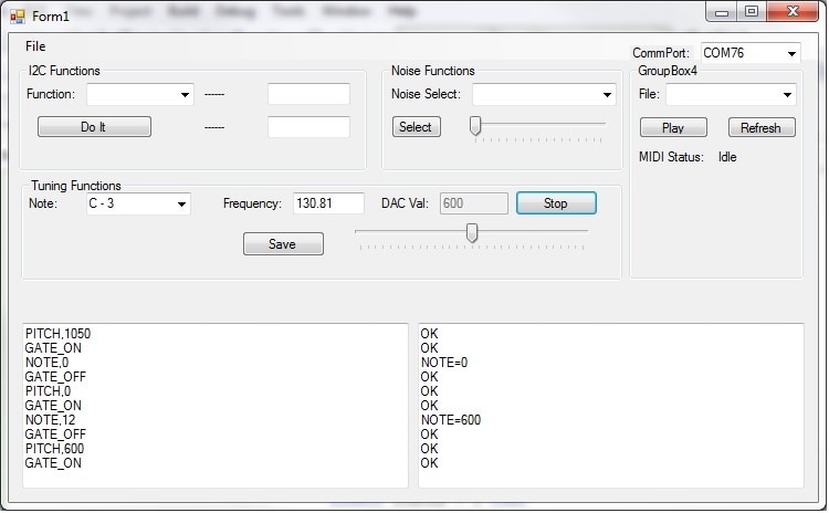
In this example I selected 'C - 3' from the 'Note:' ComboBox. The control panel software sends a command (NOTE,12) to query the SMIDI controller to get the current DAC value for the C3 note, in this case 600 (shown in the DAC Val: edit box), which is the default value. Pressing the button next to the 'DAC Val:" edit box (now showing a caption of 'Stop', it was 'Start' when I clicked on it), the control panel sends commands ('PITCH,600' and 'GATE_ON') to play the note on the synthesizer. I have routed the synthesizer output to my DMM to measure the frequency (Note the control panel displays the desired frequency ('Frequency:" 130.81). Using the slider control under the 'DAC Val:' data, adjust the setting until the desired frequency is read on the DMM. The readings are a bit jumpy (even without the SMIDI controller attached), but it looks like the desired DAC value for C3 is 645. With the slider at the correct position, click on the save button to send the command ('SAVE,12,645') to write the calibrated value into the SMIDI EEPROM. Now anytime SMIDI plays a C3 note, this DAC value will be used (instead of the rough default of 600).
So far I have only calibrated the forth octave, as the selected song only uses notes in the forth octave. I'll save the rest of the tuning for a rainy day. I have some plans to attempt an auto-tuning sequence, where I use one of the timers on the ATmega328PB as a counter (counting the synthesizer output over a fixed interval) to measure the frequency, but that too might for a rainy day.
So that pretty much covers the software description. The full sources (PC control panel and SMIDI firmware) will be attached to this blog. Now is the time to see how it all works. Here is a video of the SMIDI and the KORG volca modular synthesizer playing 'This Old Man':
What have I learned about Op-Amps? Quite a bit. Here are the ways in which I used Op-Amps in this project:
- Voltage divider/Buffer - This circuit is a resistive divider followed by an Op-Amp configured as a voltage follower which is used to proved 1.65 volts as a bias to some of the other Op-Amps.
- Complex Filtering - Two of these filters were cascaded to filter the broadband White noise signal into Pink and Brown noise. These circuits required a bit of tuning to get them properly configured in coupling and gain. I ended up injecting a simple sine wave (low frequency) to determine the necessary input resistance to achieve the proper gain (initially much too high).
- Variable Attenuation/Buffer - This circuit uses a digital potentometer to attenuate the selected noise source (White,Pink,Brown, or None) and provide it to a buffer (voltage follower) to the synthesizer.
- Two pole low-pass Filter - This circuit is used to filter to Pitch control voltage which is applied to the synthesizer. This seems to have worked out fine, as the frequency output of the synthesizers main oscillator (SOURCE) is stable as when controlled by its keyboard circuit.
What else did I learn?
- Always double (or even triple) check all device footprints/pin-outs while generating schematics and layouts. I totally misread the specification sheets on the MCP6V31T Op-Amp, believing it had the same pin-outs as the LMV321 device that I had initially designed the PCB for. It turned out that I looked at the pin-outs for a different version of the part. For as long as I have been doing this, I really should know better.
- When laying out a PCB it is always important to check the design tools, like the Electronic Rules Check (ERC) that will report nodes that are not connected. Also name net-lists with an actual name will help in keeping track of signals while routing. On this board, I left the I2C lines unrouted to the digital potentometer and never noticed it. Having to jumper these functions during the debug phase was no fun and again, I really should have know better.
Thank you all for following along with my journey to build a MIDI (like) controller for my fun little synthesizer. This was a really fun project to build and I look forward to see what other features I might add and what other interesting sounds I might be able to generate.
--------- File Attachments --------
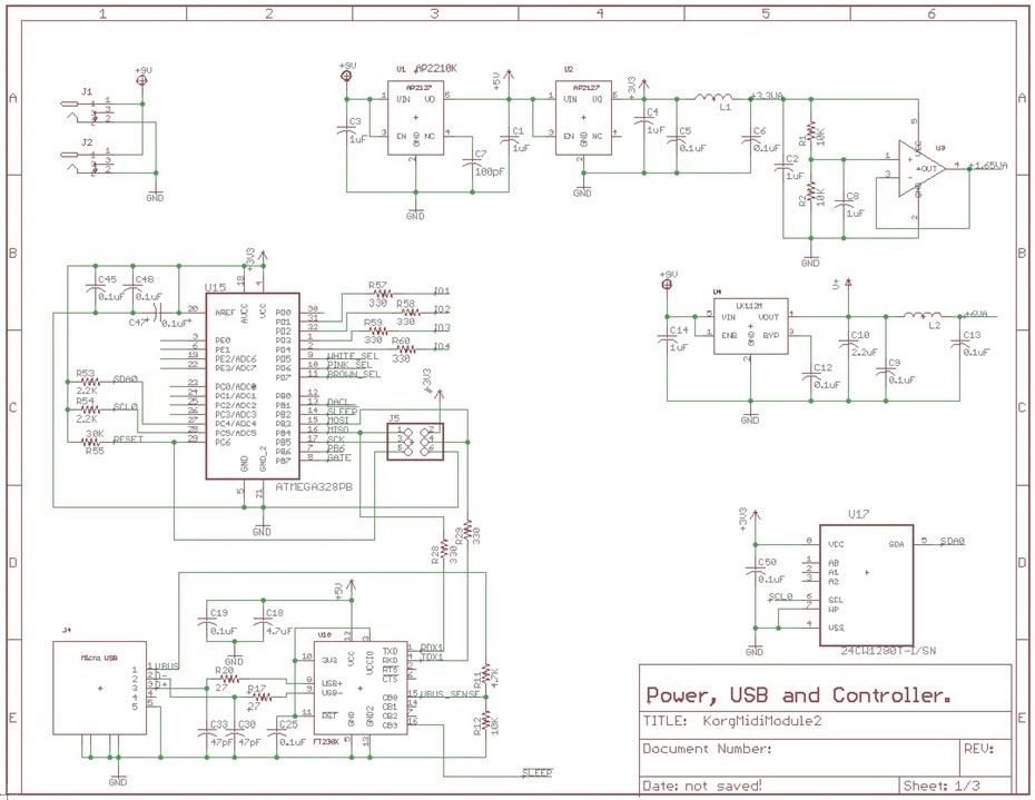
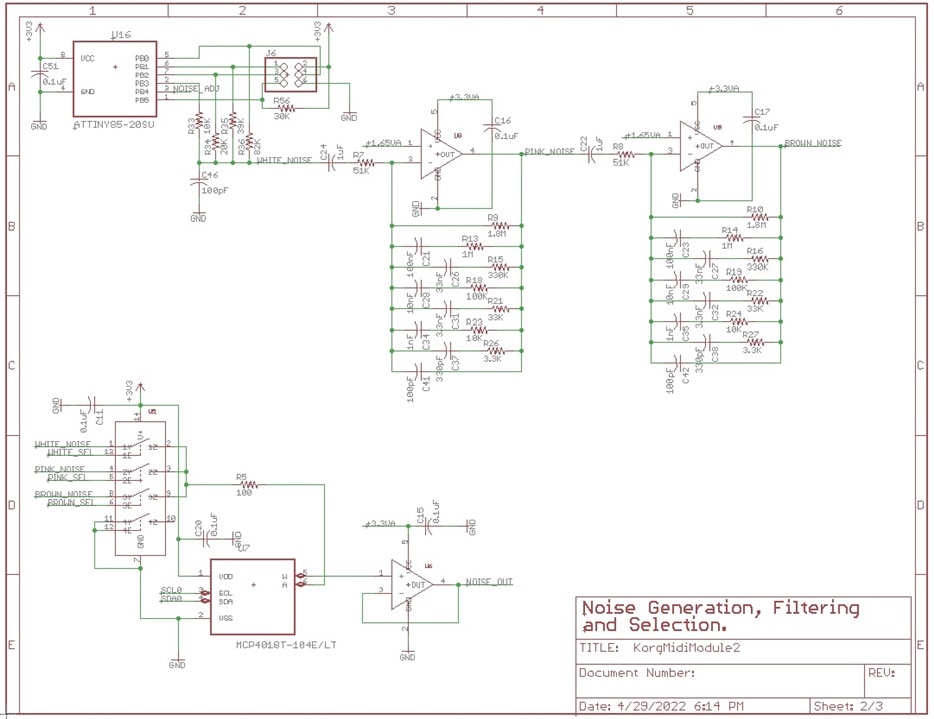
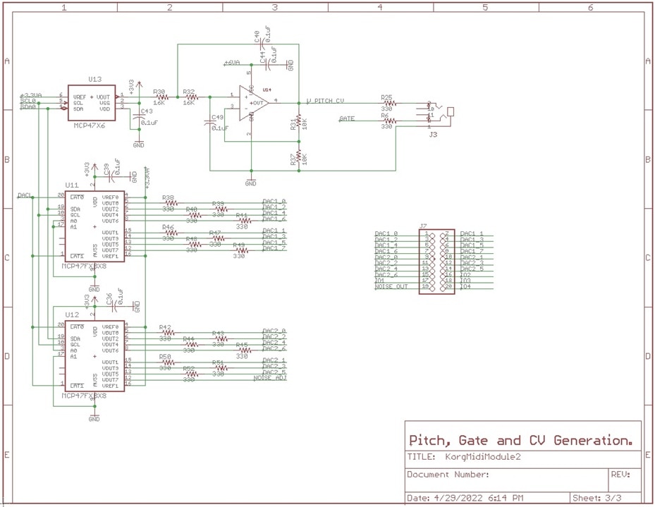
Updated schematics:
Update Layout:


Firmware Listings:
/*****************************************************
Project : KORG volca modular MIDI/controller
File    : main.c
Version : 0.1
Date    : 4/21/2022
Author  : Gene Breniman
Company : Young Embedded Systems, LLC
Comments:

Chip type               : ATmega328PB
Program type            : Application
AVR Core Clock frequency: 8.000000 MHz
Memory model            : Small
External RAM size       : 0
Data Stack size         : 512

Revisions:
*******************************************************/
#include <io.h>

#include <delay.h>

// Standard Input/Output functions
#include <stdio.h>
#include <string.h>
#include "KORG_MIDI.h"
#include "timer.h"
#include "midi.h"
#include "io.h"
#include "serial.h"
#include "EEPROM.h"
#include "TWI_Parts.h"

                        //  C      C#     D      D#     E      F      F#     G      G#     A      A#     B
unsigned int NoteVal[72] = {  50*0,  50*1,  50*2,  50*3,  50*4,  50*5,  50*6,  50*7,  50*8,  50*9,  50*10, 50*11,     // Octave = 2
                            50*12, 50*13, 50*14, 50*15, 50*16, 50*17, 50*18, 50*19, 50*20, 50*21, 50*22, 50*23,     // Octave = 3
                            50*24, 50*25, 50*26, 50*27, 50*28, 50*28, 50*30, 50*31, 50*32, 50*33, 50*34, 50*35,     // Octave = 4
                            50*36, 50*37, 50*38, 50*39, 50*40, 50*41, 50*42, 50*43, 50*44, 50*45, 50*46, 50*47,     // Octave = 5
                            50*48, 50*49, 50*50, 50*51, 50*52, 50*53, 50*54, 50*55, 50*56, 50*57, 50*58, 50*59,     // Octave = 6
                            50*60, 50*61, 50*62, 50*63, 50*64, 50*65, 50*66, 50*67, 50*68, 50*69, 50*70, 50*71};    // Octave = 7
unsigned char inBound1[80];
unsigned char outBound1[80];
unsigned char *iptr1;
unsigned char *optr1;
unsigned char unknownCommand[32] = "Unknown command\r\n\0x00";
unsigned char MidiFile[256] = {
    0xf1, 0x00, 0x00,            // DAC1-0 0
    0xf1, 0x01, 0x00,            // DAC1-1 0
    0xf2, 0x01, 0x7f,            // White noise 50%
    0x80, 0x1f, 0x03, 0x90, 0x80, 0x1c, 0x03, 0x90, 0x80, 0x1f, 0x04, 0x90,                                                  // Bar 1 - GEG
    0x80, 0x1f, 0x03, 0x90, 0x80, 0x1c, 0x03, 0x90, 0x80, 0x1f, 0x04, 0x90,                                                  // Bar 2 - GEG
    0x80, 0x21, 0x03, 0x90, 0x80, 0x1f, 0x03, 0x90, 0x80, 0x1d, 0x03, 0x90, 0x80, 0x1c, 0x03, 0x90,                          // Bar 3 - AGFE
    0x80, 0x1a, 0x03, 0x90, 0x80, 0x1c, 0x03, 0x90, 0x80, 0x1d, 0x04, 0x90,                                                  // Bar 4 - DEF
    0x80, 0x1f, 0x03, 0x90, 0x80, 0x18, 0x03, 0x90, 0x80, 0x18, 0x02, 0x90, 0x80, 0x18, 0x02, 0x90, 0x80, 0x18, 0x03, 0x90,  // Bar 5 - GCCCC
    0x80, 0x18, 0x02, 0x90, 0x80, 0x1a, 0x02, 0x90, 0x80, 0x1c, 0x02, 0x90, 0x80, 0x1d, 0x02, 0x90, 0x80, 0x1f, 0x04, 0x90,  // Bar 6 - CDEFG
    0x80, 0x1f, 0x03, 0x90, 0x80, 0x1a, 0x03, 0x90, 0x80, 0x1a, 0x03, 0x90, 0x80, 0x1d, 0x03, 0x90,                          // Bar 7 - GDDF
    0x80, 0x1c, 0x03, 0x90, 0x80, 0x1a, 0x03, 0x90, 0x80, 0x18, 0x04, 0x90,                                                  // Bar 8 - EDC

    0xf1, 0x00, 0x7f,            // DAC1-0 0x7f
    0xf1, 0x01, 0x7f,            // DAC1-1 0x7f
    0x80, 0x1f, 0x03, 0x90, 0x80, 0x1c, 0x03, 0x90, 0x80, 0x1f, 0x04, 0x90,                                                  // Bar 9 - GEG
    0x80, 0x1f, 0x03, 0x90, 0x80, 0x1c, 0x03, 0x90, 0x80, 0x1f, 0x04, 0x90,                                                  // Bar 10 - GEG
    0x80, 0x21, 0x03, 0x90, 0x80, 0x1f, 0x03, 0x90, 0x80, 0x1d, 0x03, 0x90, 0x80, 0x1c, 0x03, 0x90,                          // Bar 11 - AGFE
    0x80, 0x1a, 0x03, 0x90, 0x80, 0x1c, 0x03, 0x90, 0x80, 0x1d, 0x04, 0x90,                                                  // Bar 12 - DEF
    0x80, 0x1f, 0x03, 0x90, 0x80, 0x18, 0x03, 0x90, 0x80, 0x18, 0x02, 0x90, 0x80, 0x18, 0x02, 0x90, 0x80, 0x18, 0x03, 0x90,  // Bar 13 - GCCCC
    0x80, 0x18, 0x02, 0x90, 0x80, 0x1a, 0x02, 0x90, 0x80, 0x1c, 0x02, 0x90, 0x80, 0x1d, 0x02, 0x90, 0x80, 0x1f, 0x04, 0x90,  // Bar 14 - CDEFG
    0x80, 0x1f, 0x03, 0x90, 0x80, 0x1a, 0x03, 0x90, 0x80, 0x1a, 0x03, 0x90, 0x80, 0x1d, 0x03, 0x90,                          // Bar 15 - GDDF
    0x80, 0x1c, 0x03, 0x90, 0x80, 0x1a, 0x03, 0x90, 0x80, 0x18, 0x04, 0x90,                                                  // Bar 16 - EDC
    0xff};

void readConfiguration(void);
void writeConfiguration(void);
unsigned char decodeCommand(void);

void main(void)
{
    unsigned char serialChar;

    // Crystal Oscillator division factor: 1
    #pragma optsize-
    CLKPR=(1<<CLKPCE);
    CLKPR=(0<<CLKPCE) | (0<<CLKPS3) | (0<<CLKPS2) | (0<<CLKPS1) | (0<<CLKPS0);
    #ifdef _OPTIMIZE_SIZE_
    #pragma optsize+
    #endif

    ioInit();
    serialInit();
    timerInit();
    EEPROM_Init();
    MIDIinit();

    inBound1[0] = 0;
    iptr1 = inBound1;
    outBound1[0] = 0;
    optr1 = outBound1;
    readConfiguration();    // Globally enable interrupts
    #asm("sei")

    while (1)
    {
        // serial command processing
        if (GetSerialInputCount1())
        {
            serialChar = GetSerialByte1();
            if (serialChar == 0x0A)
            {
                *iptr1++ = 0;        // terminate string
                // command received - decode command
                switch (decodeCommand())
                {
                    case DECODE_COMMAND_UNK:
                        PutSerialString1(unknownCommand);
                        break;
                    case DECODE_COMMAND_OK:
                        // send OK reply
                        strcat( outBound1, "OK\r\n");
                        PutSerialString1(outBound1);
                        // clear outbound string
                        outBound1[0] = 0;
                        break;
                    case DECODE_COMMAND_REPLY:
                        PutSerialString1(outBound1);
                        // clear outbound string
                        outBound1[0] = 0;
                        break;
                    case DECODE_COMMAND_WAIT:
                        break;
                }
            }
            else if(serialChar == 0x0D)
            {
                // ignore CR
            }
            else
            {
                *iptr1++ = serialChar;
            }
        }
        if (mSecReady)
        {
            mSecReady = 0;

            // 100 msec processing (current limit processing)
            if (Ready100mSec)
            {
                Ready100mSec = 0;
            }
            processMIDIdata();
        }
    }
}

void readConfiguration(void)
{
    unsigned int i;
    unsigned int val;

    for (i = 0; i < 72; i++)
    {
        val = EEPROM_read_int(0x300 + i + i);
        if (val != 0xFFFF)
        {
            NoteVal[i] = val;
        }
    }
}

void writeConfiguration(void)
{
}

unsigned char decodeCommand(void)
{
    unsigned char retval = DECODE_COMMAND_UNK;
    unsigned char ctemp;
    unsigned char *params;
    unsigned int p1, p2, p3, p4, p5;

    // look for a comma separator in the command, if found, terminate string and point to remaining data
    params = strchr(inBound1, ',');
    if (params)
    {
        *params++ = 0;      // terminate command string (params now points to data)
    }

    switch(inBound1[0])
    {
        case 'A':
            break;
        case 'B':
            if (strcmp(inBound1, "BROWN") == 0)
            {
                WHITE_NOISE = 0;
                PINK_NOISE = 0;
                BROWN_NOISE = 1;
                retval = DECODE_COMMAND_OK;
            }
            break;
        case 'C':
            break;
        case 'D':
            if (strcmp(inBound1, "DAC1") == 0)
            {
                ctemp = sscanf( params, "%d,%d", &p1, &p2);
                if (ctemp == 2 )
                {
                    WriteDAC1Value(p1, p2);
                }
                retval = DECODE_COMMAND_OK;
            }
            else if (strcmp(inBound1, "DAC2") == 0)
            {
                ctemp = sscanf( params, "%d,%d", &p1, &p2);
                if (ctemp == 2 )
                {
                    WriteDAC2Value(p1, p2);
                }
                retval = DECODE_COMMAND_OK;
            }
            else if (strcmp(inBound1, "DIGPOT") == 0)
            {
                ctemp = sscanf( params, "%d", &p1);
                if (ctemp == 1 )
                {
                    WriteDigPotValue(p1);
                }
                retval = DECODE_COMMAND_OK;
            }
            break;
        case 'G':
            if (strcmp(inBound1, "GATE_ON") == 0)
            {
                GATE = 1;
                retval = DECODE_COMMAND_OK;
            }
            else if (strcmp(inBound1, "GATE_OFF") == 0)
            {
                GATE = 0;
                retval = DECODE_COMMAND_OK;
            }
            break;
        case 'H':
            if (strcmp(inBound1, "HELLO?") == 0)
            {
                retval = DECODE_COMMAND_OK;
            }
            break;
        case 'M':
            if (strcmp(inBound1, "MSTAT?") == 0)
            {
                p1 = MIDIstat();
                sprintf(outBound1, "MSTAT?=%d\r\n", p1);
                retval = DECODE_COMMAND_REPLY;
            }
            break;
        case 'N':
            if (strcmp(inBound1, "NONOISE") == 0)
            {
                WHITE_NOISE = 0;
                PINK_NOISE = 0;
                BROWN_NOISE = 0;
                retval = DECODE_COMMAND_OK;
            }
            if (strcmp(inBound1, "NOTE") == 0)
            {
                ctemp = sscanf( params, "%d", &p1);
                if (ctemp == 1 )
                {
                    p2 = NoteVal[p1];
                    sprintf(outBound1, "NOTE=%d\r\n", p2);
                }
                retval = DECODE_COMMAND_REPLY;
            }
            break;
        case 'P':
            if (strcmp(inBound1, "PITCH") == 0)
            {
                ctemp = sscanf( params, "%d", &p1);
                if (ctemp == 1 )
                {
                    WritePitchValue(p1);
                }
                retval = DECODE_COMMAND_OK;
            }
            else if (strcmp(inBound1, "PINK") == 0)
            {
                WHITE_NOISE = 0;
                BROWN_NOISE = 0;
                PINK_NOISE = 1;
                retval = DECODE_COMMAND_OK;
            }
            else if (strcmp(inBound1, "PLAY") == 0)
            {
                MIDIstart(MidiFile);
                retval = DECODE_COMMAND_OK;
            }
            break;
        case 'R':
            if (strcmp(inBound1, "REE") == 0)
            {
                ctemp = sscanf( params, "%d", &p1);
                if (ctemp == 1 )
                {
                    p2 = ReadEEPROM(p1);
                    sprintf(outBound1, "REE=%d\r\n", p2);
                }
                retval = DECODE_COMMAND_REPLY;
            }
            break;
        case 'S':
            if (strcmp(inBound1, "SAVE") == 0)
            {
                ctemp = sscanf( params, "%d,%d", &p1,&p2);
                if (ctemp == 2 )
                {
                    NoteVal[p1] = p2;
                    EEPROM_write_int((0x300 + (p1<<1)), p2);
                }
                retval = DECODE_COMMAND_OK;
            }
            else if (strcmp(inBound1, "STOP") == 0)
            {
                MIDIstop();
                retval = DECODE_COMMAND_OK;
            }
            break;
        case 'W':
            if (strcmp(inBound1, "WHITE") == 0)
            {
                PINK_NOISE = 0;
                BROWN_NOISE = 0;
                WHITE_NOISE = 1;
                retval = DECODE_COMMAND_OK;
            }
            else if (strcmp(inBound1, "WEE") == 0)
            {
                ctemp = sscanf( params, "%d,%d", &p1, &p2);
                if (ctemp == 2 )
                {
                    WriteEEPROM(p1, p2);
                }
                retval = DECODE_COMMAND_OK;
            }
            break;
    }
    // clear inBound1 data
    iptr1 = inBound1;
    *iptr1 = 0;
    return retval;
}
/*****************************************************
Project : KORG volca modular MIDI/controller
File    : io.c
Version : 0.1
Date    : 4/21/2022
Author  : Gene Breniman
Company : Young Embedded Systems, LLC
Comments:

Chip type               : ATmega328PB
Program type            : Application
AVR Core Clock frequency: 8.000000 MHz
Memory model            : Small
External RAM size       : 0
Data Stack size         : 512

Revisions:
*******************************************************/

#include <io.h>

void ioInit(void)
{
    // Input/Output Ports initialization
    // Port B initialization
    // Function: Bit7=Out Bit6=In Bit5=In Bit4=In Bit3=In Bit2=In Bit1=Out Bit0=In
    DDRB = (1<<DDB7) | (0<<DDB6) | (0<<DDB5) | (0<<DDB4) | (0<<DDB3) | (0<<DDB2) | (1<<DDB1) | (0<<DDB0);
    // State: Bit7=0 Bit6=T Bit5=T Bit4=T Bit3=T Bit2=T Bit1=0 Bit0=T
    PORTB = (0<<PORTB7) | (0<<PORTB6) | (0<<PORTB5) | (0<<PORTB4) | (0<<PORTB3) | (0<<PORTB2) | (1<<PORTB1) | (0<<PORTB0);

    // Port C initialization
    // Function: Bit6=In Bit5=In Bit4=In Bit3=In Bit2=In Bit1=In Bit0=In
    DDRC = (0<<DDC6) | (0<<DDC5) | (0<<DDC4) | (0<<DDC3) | (0<<DDC2) | (0<<DDC1) | (0<<DDC0);
    // State: Bit6=T Bit5=T Bit4=T Bit3=T Bit2=T Bit1=T Bit0=T
    PORTC = (0<<PORTC6) | (0<<PORTC5) | (0<<PORTC4) | (0<<PORTC3) | (0<<PORTC2) | (0<<PORTC1) | (0<<PORTC0);

    // Port D initialization
    // Function: Bit7=Out Bit6=Out Bit5=Out Bit4=Out Bit3=Out Bit2=Out Bit1=Out Bit0=In
    DDRD = (1<<DDD7) | (1<<DDD6) | (1<<DDD5) | (1<<DDD4) | (1<<DDD3) | (1<<DDD2) | (1<<DDD1) | (0<<DDD0);
    // State: Bit7=0 Bit6=0 Bit5=0 Bit4=0 Bit3=0 Bit2=0 Bit1=0 Bit0=T
    PORTD = (0<<PORTD7) | (0<<PORTD6) | (0<<PORTD5) | (0<<PORTD4) | (0<<PORTD3) | (0<<PORTD2) | (0<<PORTD1) | (0<<PORTD0);

    // Port E initialization
    // Function: Bit3=In Bit2=In Bit1=In Bit0=In
    DDRE = (0<<DDE3) | (0<<DDE2) | (0<<DDE1) | (0<<DDE0);
    // State: Bit3=T Bit2=T Bit1=T Bit0=T
    PORTE = (0<<PORTE3) | (0<<PORTE2) | (0<<PORTE1) | (0<<PORTE0);

    // External Interrupt(s) initialization
    // INT0: Off
    // INT1: Off
    // Interrupt on any change on pins PCINT0-7: Off
    // Interrupt on any change on pins PCINT8-14: Off
    // Interrupt on any change on pins PCINT16-23: Off
    // Interrupt on any change on pins PCINT24-27: Off
    EICRA = (0<<ISC11) | (0<<ISC10) | (0<<ISC01) | (0<<ISC00);
    EIMSK = (0<<INT1) | (0<<INT0);
    PCICR = (0<<PCIE3) | (0<<PCIE2) | (0<<PCIE1) | (0<<PCIE0);
}
/*****************************************************
Project : KORG volca modular MIDI/controller
File    : EEPROM.c
Version : 0.1
Date    : 4/21/2022
Author  : Gene Breniman
Company : Young Embedded Systems, LLC
Comments:

Chip type               : ATmega328PB
Program type            : Application
AVR Core Clock frequency: 8.000000 MHz
Memory model            : Small
External RAM size       : 0
Data Stack size         : 512

Revisions:
*******************************************************/
#include <io.h>
#include <EEPROM.h>
#include <delay.h>
#include "EEPROM.h"

static unsigned char EE_defaulted;

// **************************************************************************************************
// FUNCTION NAME:        EEPROM_Init()
// **************************************************************************************************
// DESCRIPTION:
//  This routine is called to initialize the EEPROM/values.
// **************************************************************************************************
// Global(s) Accessed:
//     NONE
//
// **************************************************************************************************
// Input(s):
//     NONE
//
// Output(s):
//     EE_defaulted cleared
//
// **************************************************************************************************
// Return Type:        NONE
// **************************************************************************************************
void EEPROM_Init(void)
{
    EE_defaulted = 0;
}

// **************************************************************************************************
// FUNCTION NAME:        EEPROM_defaults()
// **************************************************************************************************
// DESCRIPTION:
//  This routine is called to initialize the EEPROM/values.
// **************************************************************************************************
// Global(s) Accessed:
//     NONE
//
// **************************************************************************************************
// Input(s):
//     NONE
//
// Output(s):
//     NONE
//
// **************************************************************************************************
// Return Type:        0 - no defaults encountered / 1 - defaults were encountered during reads
// **************************************************************************************************
unsigned char EEPROM_defaults(void)
{
    return EE_defaulted;
}

// **************************************************************************************************
// FUNCTION NAME:        EEPROM_write()
// **************************************************************************************************
// DESCRIPTION:
//  This routine is called to write data to the specified EEPROM address.
// **************************************************************************************************
// Global(s) Accessed:
//     NONE
//
// **************************************************************************************************
// Input(s):
//     unsigned int uiAddress    - EEPROM address to write
//  char ucData        - data to write to EEPROM
//
// Output(s):
//     NONE
//
// **************************************************************************************************
// Return Type:        NONE
// **************************************************************************************************
void EEPROM_write(unsigned int uiAddress, unsigned char ucData)
{
    unsigned char ucRData;

    // read first to determine if the write is necessary
    ucRData = EEPROM_read(uiAddress);
    if( ucRData != ucData)
    {
        // EEPROM needs to be updated
        // Wait for completion of previous write
        while(EECR & (1<<EEPE));
        // Set up address and data registers
        EEAR = uiAddress;
        EEDR = ucData;
    #asm("cli")
        // Write logical one to EEMPE
        EECR |= (1<<EEMPE);
        // Start eeprom write by setting EEPE
        EECR |= (1<<EEPE);
    #asm("sei")
    }
}

// **************************************************************************************************
// FUNCTION NAME:        EEPROM_read()
// **************************************************************************************************
// DESCRIPTION:
//  This routine is called to read data fromo the specified EEPROM address.
// **************************************************************************************************
// Global(s) Accessed:
//     NONE
//
// **************************************************************************************************
// Input(s):
//  unsigned int uiAddress    - EEPROM address to read
//
// Output(s):
//     NONE
//
// **************************************************************************************************
// Return Type:        char - data read from the EEPROM (at specified address)
// **************************************************************************************************
unsigned char EEPROM_read(unsigned int uiAddress)
{
    // Wait for completion of previous write
    while(EECR & (1<<EEPE))
        ;
    // Set up address register
    EEAR = uiAddress;
    // Start eeprom read by writing EERE
    EECR |= (1<<EERE);
    // Return data from data register
    return EEDR;
}

// **************************************************************************************************
// FUNCTION NAME:        EEPROM_read_default()
// **************************************************************************************************
// DESCRIPTION:
//  This routine is called to read data fromo the specified EEPROM address, return default value if 0xFF.
// **************************************************************************************************
// Global(s) Accessed:
//     NONE
//
// **************************************************************************************************
// Input(s):
//  unsigned int uiAddress    - EEPROM address to read
//  unsigned char defaultValue - Default value to return if EEPROM value is 0xFF
//
// Output(s):
//     NONE
//
// **************************************************************************************************
// Return Type:        char - data read from the EEPROM (at specified address)
// **************************************************************************************************
unsigned char EEPROM_read_default(unsigned int uiAddress, unsigned char defaultValue)
{
    unsigned char EEdata;

    EEdata = EEPROM_read(uiAddress);
    if (EEdata == 0xFF)
    {
        EEdata = defaultValue;
        EE_defaulted = 1;
    }
    return EEdata;
}

// **************************************************************************************************
// FUNCTION NAME:        EEPROM_write_int()
// **************************************************************************************************
// DESCRIPTION:
//  This routine is called to write data (int) to the specified EEPROM address.
// **************************************************************************************************
// Global(s) Accessed:
//     NONE
//
// **************************************************************************************************
// Input(s):
//     unsigned int uiAddress    - EEPROM address to write
//  unsigned int uiData        - data to write to EEPROM
//
// Output(s):
//     NONE
//
// **************************************************************************************************
// Return Type:        NONE
// **************************************************************************************************
extern void EEPROM_write_int(unsigned int uiAddress, unsigned int uiData)
{
    unsigned char ucData;

    ucData = (uiData >> 8);
    EEPROM_write(uiAddress, ucData);
    ucData = (uiData & 0xFF);
    EEPROM_write(uiAddress+1, ucData);
}

// **************************************************************************************************
// FUNCTION NAME:        EEPROM_read_int()
// **************************************************************************************************
// DESCRIPTION:
//  This routine is called to read int data fromo the specified EEPROM address.
// **************************************************************************************************
// Global(s) Accessed:
//     NONE
//
// **************************************************************************************************
// Input(s):
//  unsigned int uiAddress    - EEPROM address to read
//
// Output(s):
//     NONE
//
// **************************************************************************************************
// Return Type:        int - data read from the EEPROM (at specified address)
// **************************************************************************************************
extern unsigned int EEPROM_read_int(unsigned int uiAddress)
{
    unsigned char ucData;
    unsigned int uiData;

    ucData = EEPROM_read(uiAddress);
    uiData = ((unsigned int) ucData) << 8;
    ucData = EEPROM_read(uiAddress+1);
    uiData |= ucData;
    return uiData;
}

// **************************************************************************************************
// FUNCTION NAME:        EEPROM_read_default_int()
// **************************************************************************************************
// DESCRIPTION:
//  This routine is called to read data int fromo the specified EEPROM address, return default value if 0xFFFF.
// **************************************************************************************************
// Global(s) Accessed:
//     NONE
//
// **************************************************************************************************
// Input(s):
//  unsigned int uiAddress    - EEPROM address to read
//  unsigned int defaultValue - Default value to return if EEPROM value is 0xFFFF
//
// Output(s):
//     NONE
//
// **************************************************************************************************
// Return Type:        char - data read from the EEPROM (at specified address)
// **************************************************************************************************
extern unsigned int EEPROM_read_default_int(unsigned int uiAddress, unsigned int defaultValue)
{
    unsigned int uiData;

    uiData = EEPROM_read_int(uiAddress);
    if (uiData == 0xFFFF)
    {
        uiData = defaultValue;
        EE_defaulted = 1;
    }
    return uiData;
}
/*****************************************************
Project : KORG volca modular MIDI/controller
File    : serial.c
Version : 0.1
Date    : 4/21/2022
Author  : Gene Breniman
Company : Young Embedded Systems, LLC
Comments:

Chip type               : ATmega328PB
Program type            : Application
AVR Core Clock frequency: 8.000000 MHz
Memory model            : Small
External RAM size       : 0
Data Stack size         : 512

Revisions:
*******************************************************/

#include "io.h"
#include "serial.h"
#include <io.h>
// TWI functions
#include <twi.h>

static unsigned char status1;
// USART1 Receiver buffer

#define RX_BUFFER_SIZE1 64              // does not need to be a power of two
char rx_buffer1[RX_BUFFER_SIZE1];

unsigned char rx_wr_index1 = 0;
unsigned char rx_rd_index1 = 0;
unsigned char rx_counter1 = 0;

// This flag is set on USART1 Receiver buffer overflow
bit rx_buffer_overflow1;

// USART1 Receiver interrupt service routine
interrupt [USART1_RXC] void usart1_rx_isr(void)
{
    char data;
    status1 = UCSR1A & (FRAMING_ERROR | PARITY_ERROR | DATA_OVERRUN);
    data = UDR1;
    if (status1 == 0)
    {
        rx_buffer1[rx_wr_index1++] = data;
        if (rx_wr_index1 == RX_BUFFER_SIZE1)
        {
            rx_wr_index1 = 0;
        }
        if (++rx_counter1 == RX_BUFFER_SIZE1)
        {
            rx_counter1 = 0;
            rx_buffer_overflow1 = 1;
        }
    }
}

// Get a character from the USART1 Receiver buffer
unsigned char GetSerialByte1(void)
{
    char data;

    if (rx_counter1 == 0)
        return 0;
    data = rx_buffer1[rx_rd_index1++];
    if (rx_rd_index1 == RX_BUFFER_SIZE1)
    {
        rx_rd_index1 = 0;
    }
    #asm("cli")
    --rx_counter1;
    #asm("sei")
    return data;
}

unsigned char GetSerialInputCount1(void)
{
    return rx_counter1;
}

unsigned char GetSerialStatus1(void)
{
    return status1;
}

// USART1 Transmitter buffer
#define TX_BUFFER_SIZE1 64              // does not need to be a power of two
char tx_buffer1[TX_BUFFER_SIZE1];

unsigned char tx_wr_index1 = 0;
unsigned char tx_rd_index1 = 0;
unsigned char tx_counter1 = 0;

// USART1 Transmitter interrupt service routine
interrupt [USART1_TXC] void usart1_tx_isr(void)
{
    if (tx_counter1)
    {
        --tx_counter1;
        UDR1 = tx_buffer1[tx_rd_index1++];
        if (tx_rd_index1 == TX_BUFFER_SIZE1)
        {
            tx_rd_index1 = 0;
        }
    }
}

// Get a character from the USART Receiver buffer
void PutSerialByte1(unsigned char data)
{
    if (tx_counter1 == TX_BUFFER_SIZE1)
        return;
    if (tx_counter1 || ((UCSR1A & DATA_REGISTER_EMPTY) == 0))
    {
        #asm("cli")
        tx_buffer1[tx_wr_index1++] = data;
        if (tx_wr_index1 == RX_BUFFER_SIZE1)
        {
            tx_wr_index1 = 0;
        }
        tx_counter1++;
        #asm("sei")
    }
    else
    {
        UDR1 = data;
    }
}

void PutSerialString1(unsigned char *data)
{
    while (*data)
    {
        PutSerialByte1(*data);
        data++;
    }
}

void serialInit(void)
{
    // USART0 initialization
    // USART0 disabled
    UCSR0B = (0<<RXCIE0) | (0<<TXCIE0) | (0<<UDRIE0) | (0<<RXEN0) | (0<<TXEN0) | (0<<UCSZ02) | (0<<RXB80) | (0<<TXB80);

    // Ensure that the USART0 is disabled to preserve power
    PRR0 |= 1<<PRUSART0;

    // USART1 initialization
    // Communication Parameters: 8 Data, 1 Stop, No Parity
    // USART1 Receiver: On
    // USART1 Transmitter: On
    // USART1 Mode: Asynchronous
    // USART1 Baud Rate: 9600
    UCSR1A = (0<<RXC1) | (0<<TXC1) | (0<<UDRE1) | (0<<FE1) | (0<<DOR1) | (0<<UPE1) | (0<<U2X1) | (0<<MPCM1);
    UCSR1B = (1<<RXCIE1) | (1<<TXCIE1) | (0<<UDRIE1) | (1<<RXEN1) | (1<<TXEN1) | (0<<UCSZ12) | (0<<RXB81) | (0<<TXB81);
    UCSR1C = (0<<UMSEL11) | (0<<UMSEL10) | (0<<UPM11) | (0<<UPM10) | (0<<USBS1) | (1<<UCSZ11) | (1<<UCSZ10) | (0<<UCPOL1);
    UBRR1H = 0x00;
    UBRR1L = 0x33;

    // Ensure that the USART1 is enabled
    PRR0 &= ~(1<<PRUSART1);


    // SPI initialization
    // SPI disabled
    SPCR = (0<<SPIE) | (0<<SPE) | (0<<DORD) | (0<<MSTR) | (0<<CPOL) | (0<<CPHA) | (0<<SPR1) | (0<<SPR0);
    SPCR1 = (0<<SPIE) | (0<<SPE) | (0<<DORD) | (0<<MSTR) | (0<<CPOL) | (0<<CPHA) | (0<<SPR1) | (0<<SPR0);

    // Ensure that the SPI0 is disabled to preserve power
    PRR0 |= 1<<PRSPI0;

    // TWI initialization
    // Mode: TWI Master
    // Bit Rate: 100 kHz
    twi_master_init(100);

    // Ensure that the TWI0 is enabled
    PRR0 &= ~(1<<PRTWI0);
}
/*****************************************************
Project : KORG volca modular MIDI/controller
File    : timer.c
Version : 0.1
Date    : 4/21/2022
Author  : Gene Breniman
Company : Young Embedded Systems, LLC
Comments:

Chip type               : ATmega328PB
Program type            : Application
AVR Core Clock frequency: 8.000000 MHz
Memory model            : Small
External RAM size       : 0
Data Stack size         : 512

Revisions:
*******************************************************/

#include "timer.h"
#include "io.h"
#include <io.h>

static unsigned int ticks1mS;
static unsigned int ticks10mS;
static unsigned char ticks100mS;
unsigned char mSecReady;
unsigned char Ready100mSec;
unsigned char MIDItimer;

// Timer 0 overflow interrupt service routine (1ms timer)
interrupt [TIM0_OVF] void timer0_ovf_isr(void)
{
    // Reinitialize Timer 0 value
    TCNT0 = TMR0_RELOAD;

    if(++ticks1mS >= 10)
    {
        if (++ticks10mS >= 10)
        {
            ticks10mS = 0;
            Ready100mSec = 1;
        }
        ticks1mS = 0;
        MIDItimer++;
    }

    mSecReady = 1;
}

void timerInit(void)
{
    // Timer/Counter 0 initialization
    // Clock source: System Clock
    // Clock value: 125.000 kHz
    // Mode: Normal top=0xFF
    // OC0A output: Disconnected
    // OC0B output: Disconnected
    // Timer Period: 1 ms
    TCCR0A = (0<<COM0A1) | (0<<COM0A0) | (0<<COM0B1) | (0<<COM0B0) | (0<<WGM01) | (0<<WGM00);
    TCCR0B = (0<<WGM02) | (0<<CS02) | (1<<CS01) | (1<<CS00);
    TCNT0 = TMR0_RELOAD;
    OCR0A = 0x00;
    OCR0B = 0x00;

    // Ensure that the Timer/Counter 0 is enabled
    PRR0 &= ~(1<<PRTIM0);

    // Timer/Counter 1 initialization
    // Clock source: System Clock
    // Clock value: Timer1 Stopped
    // Mode: Normal top=0xFFFF
    // OC1A output: Disconnected
    // OC1B output: Disconnected
    // Noise Canceler: Off
    // Input Capture on Falling Edge
    // Timer1 Overflow Interrupt: Off
    // Input Capture Interrupt: Off
    // Compare A Match Interrupt: Off
    // Compare B Match Interrupt: Off
    TCCR1A = (0<<COM1A1) | (0<<COM1A0) | (0<<COM1B1) | (0<<COM1B0) | (0<<WGM11) | (0<<WGM10);
    TCCR1B = (0<<ICNC1) | (0<<ICES1) | (0<<WGM13) | (0<<WGM12) | (0<<CS12) | (0<<CS11) | (0<<CS10);
    TCNT1H = 0x00;
    TCNT1L = 0x00;
    ICR1H = 0x00;
    ICR1L = 0x00;
    OCR1AH = 0x00;
    OCR1AL = 0x00;
    OCR1BH = 0x00;
    OCR1BL = 0x00;

    // Ensure that the Timer/Counter 1 is disabled to preserve power
    PRR0 |= 1<<PRTIM1;

    // Timer/Counter 2 initialization
    // Clock source: System Clock
    // Clock value: Timer2 Stopped
    // Mode: Normal top=0xFF
    // OC2A output: Disconnected
    // OC2B output: Disconnected
    ASSR = (0<<EXCLK) | (0<<AS2);
    TCCR2A = (0<<COM2A1) | (0<<COM2A0) | (0<<COM2B1) | (0<<COM2B0) | (0<<WGM21) | (0<<WGM20);
    TCCR2B = (0<<WGM22) | (0<<CS22) | (0<<CS21) | (0<<CS20);
    TCNT2 = 0x00;
    OCR2A = 0x00;
    OCR2B = 0x00;

    // Ensure that the Timer/Counter 2 is disabled to preserve power
    PRR0 |= 1<<PRTIM2;

    // Timer/Counter 3 initialization
    // Clock source: System Clock
    // Clock value: Timer3 Stopped
    // Mode: Normal top=0xFFFF
    // OC3A output: Disconnected
    // OC3B output: Disconnected
    // Noise Canceler: Off
    // Input Capture on Falling Edge
    // Timer3 Overflow Interrupt: Off
    // Input Capture Interrupt: Off
    // Compare A Match Interrupt: Off
    // Compare B Match Interrupt: Off
    TCCR3A = (0<<COM3A1) | (0<<COM3A0) | (0<<COM3B1) | (0<<COM3B0) | (0<<WGM31) | (0<<WGM30);
    TCCR3B = (0<<ICNC3) | (0<<ICES3) | (0<<WGM33) | (0<<WGM32) | (0<<CS32) | (0<<CS31) | (0<<CS30);
    TCNT3H = 0x00;
    TCNT3L = 0x00;
    ICR3H = 0x00;
    ICR3L = 0x00;
    OCR3AH = 0x00;
    OCR3AL = 0x00;
    OCR3BH = 0x00;
    OCR3BL = 0x00;

    // Timer/Counter 4 initialization
    // Clock source: System Clock
    // Clock value: Timer4 Stopped
    // Mode: Normal top=0xFFFF
    // OC4A output: Disconnected
    // OC4B output: Disconnected
    // Noise Canceler: Off
    // Input Capture on Falling Edge
    // Timer4 Overflow Interrupt: Off
    // Input Capture Interrupt: Off
    // Compare A Match Interrupt: Off
    // Compare B Match Interrupt: Off
    TCCR4A = (0<<COM4A1) | (0<<COM4A0) | (0<<COM4B1) | (0<<COM4B0) | (0<<WGM41) | (0<<WGM40);
    TCCR4B = (0<<ICNC4) | (0<<ICES4) | (0<<WGM43) | (0<<WGM42) | (0<<CS42) | (0<<CS41) | (0<<CS40);
    TCNT4H = 0x00;
    TCNT4L = 0x00;
    ICR4H = 0x00;
    ICR4L = 0x00;
    OCR4AH = 0x00;
    OCR4AL = 0x00;
    OCR4BH = 0x00;
    OCR4BL = 0x00;

    // Timer/Counter 0 Interrupt(s) initialization
    TIMSK0=(0<<OCIE0B) | (0<<OCIE0A) | (1<<TOIE0);

    // Timer/Counter 1 Interrupt(s) initialization
    TIMSK1=(0<<ICIE1) | (0<<OCIE1B) | (0<<OCIE1A) | (0<<TOIE1);

    // Timer/Counter 2 Interrupt(s) initialization
    TIMSK2=(0<<OCIE2B) | (0<<OCIE2A) | (0<<TOIE2);

    // Timer/Counter 3 Interrupt(s) initialization
    TIMSK3=(0<<ICIE3) | (0<<OCIE3B) | (0<<OCIE3A) | (0<<TOIE3);

    // Timer/Counter 4 Interrupt(s) initialization
    TIMSK4=(0<<ICIE4) | (0<<OCIE4B) | (0<<OCIE4A) | (0<<TOIE4);

    ticks1mS = 0;
    ticks10mS = 0;
    ticks100mS = 0;
    mSecReady = 0;
    Ready100mSec = 0;
    MIDItimer = 0;
}

void startMIDItimer(void)
{
    MIDItimer = 0;
}
/*****************************************************
Project : KORG volca modular MIDI/controller
File    : TWI_Parts.c
Version : 0.1
Date    : 4/21/2022
Author  : Gene Breniman
Company : Young Embedded Systems, LLC
Comments:

Chip type               : ATmega328PB
Program type            : Application
AVR Core Clock frequency: 8.000000 MHz
Memory model            : Small
External RAM size       : 0
Data Stack size         : 512

Revisions:
*******************************************************/
#include "TWI_Parts.h"
#include "EEPROM.h"
#include "io.h"

// TWI functions
#include <twi.h>
#include <string.h>
#include <stdio.h>

unsigned char TWI_out[8];
unsigned char TWI_in[8];

void WritePitchValue(unsigned int PitchVal)
{
    TWI_out[0] = ((PitchVal >> 8) & 0x0F);
    TWI_out[1] = (PitchVal  & 0xFF);
    twi_master_trans(PITCH_DAC_ADDR, TWI_out, 2, NULL, 0);
}

void WriteDAC1Value(unsigned int Value, unsigned char Channel)
{
    TWI_out[0] = Channel << 3;
    TWI_out[1] = 0;
    TWI_out[2] = (Value  & 0xFF);
    twi_master_trans(DAC1_ADDR, TWI_out, 3, NULL, 0);
    DAC_LATCH = 0;
    DAC_LATCH = 1;
}

void WriteDAC2Value(unsigned int Value, unsigned char Channel)
{
    TWI_out[0] = Channel << 3;
    TWI_out[1] = 0;
    TWI_out[2] = (Value  & 0xFF);
    twi_master_trans(DAC2_ADDR, TWI_out, 3, NULL, 0);
    DAC_LATCH = 0;
    DAC_LATCH = 1;
}

void WriteDigPotValue(unsigned char Attenuation)
{
    TWI_out[0] = Attenuation;
    twi_master_trans(DIG_POT, TWI_out, 1, NULL, 0);
}

void WriteEEPROM(unsigned int Address, unsigned char Data)
{
    TWI_out[0] = ((Address >> 8) & 0x3F);
    TWI_out[1] = (Address  & 0xFF);
    TWI_out[2] = Data;
    twi_master_trans(EEPROM, TWI_out, 3, NULL, 0);
}

unsigned char ReadEEPROM(unsigned int Address)
{
    TWI_out[0] = ((Address >> 8) & 0x3F);
    TWI_out[1] = (Address  & 0xFF);
    twi_master_trans(EEPROM, TWI_out, 2, TWI_in, 1);
    return TWI_in[0];
}
/*****************************************************
Project : KORG volca modular MIDI/controller
File    : midi.c
Version : 0.1
Date    : 4/29/2022
Author  : Gene Breniman
Company : Young Embedded Systems, LLC
Comments:

Chip type               : ATmega328PB
Program type            : Application
AVR Core Clock frequency: 8.000000 MHz
Memory model            : Small
External RAM size       : 0
Data Stack size         : 512

Revisions:
*******************************************************/

#include "KORG_MIDI.h"
#include "TWI_Parts.h"
#include "midi.h"
#include "io.h"
#include "timer.h"

static unsigned char waitVal;
static unsigned char MIDIstate;
static unsigned char *MIDIptr;
static unsigned char TempoVal;
static unsigned char Note;

void MIDIinit(void)
{
    waitVal = 0;
    MIDIstate = MIDI_IDLE;
    TempoVal = 50;              // start with 120 BPM
}

void MIDIstart(unsigned char *mdata)
{
    MIDIstate = MIDI_FETCH_TOKEN;
    waitVal = 0;
    MIDIptr = mdata;
}

void MIDIstop(void)
{
    MIDIstate = MIDI_IDLE;
    waitVal = 0;
    GATE = 0;
}

unsigned char MIDIstat(void)
{
    return MIDIstate;
}

void processMIDIdata(void)
{
    unsigned char ucTemp;
    unsigned char DACval;

    if (waitVal)
    {
        if (MIDItimer < waitVal)
        {
            return;
        }
        waitVal = 0;
    }

    switch (MIDIstate)
    {
        case MIDI_IDLE:
            break;

        case MIDI_READ_HEADER:
            break;

        case MIDI_FETCH_TOKEN:
            ucTemp = *MIDIptr++;
            switch (ucTemp)
            {
                case KEY_DOWN:
                    Note = *MIDIptr++;
                    WritePitchValue(NoteVal[Note]);
                    GATE = 1;
                    ucTemp = *MIDIptr++;
                    switch (ucTemp)
                    {
                        case 1:                         // 1/16
                            waitVal = (TempoVal >> 2);
                            break;
                        case 2:                         // 1/8
                            waitVal = (TempoVal >> 1);
                            break;
                        case 3:                         // 1/4
                            waitVal = TempoVal;
                            break;
                        case 4:                         // 1/2
                            waitVal = (TempoVal << 1);
                            break;
                        case 5:                         // whole
                            waitVal = (TempoVal << 2);
                            break;
                    }
                    waitVal -= 10;
                    startMIDItimer();
                    break;
                case KEY_UP:
                    GATE = 0;
                    waitVal = 10;
                    startMIDItimer();
                    break;
                case TEMPO:
                    TempoVal = *MIDIptr++;
                    break;
                case CV_CONTROL:
                    ucTemp = *MIDIptr++;
                    DACval = *MIDIptr++;
                    if (ucTemp & 0x8)
                    {
                        WriteDAC2Value(DACval, ucTemp & 0x07);
                    }
                    else
                    {
                        WriteDAC1Value(DACval, ucTemp);
                    }
                    break;
                case NOISE_SEL:
                    ucTemp = *MIDIptr++;
                    DACval = *MIDIptr++;
                    switch (ucTemp & 0x03)
                    {
                        case 0:                         // Off (no noise)
                            WHITE_NOISE = 0;
                            PINK_NOISE = 0;
                            BROWN_NOISE = 0;
                            break;

                        case 1:                         // White noise
                            WHITE_NOISE = 1;
                            PINK_NOISE = 0;
                            BROWN_NOISE = 0;
                            break;

                        case 2:                         // Pink noise
                            WHITE_NOISE = 0;
                            PINK_NOISE = 1;
                            BROWN_NOISE = 0;
                            break;

                        case 3:                         // Brown noise
                            WHITE_NOISE = 0;
                            PINK_NOISE = 0;
                            BROWN_NOISE = 1;
                            break;

                    }
                    WriteDigPotValue(DACval);
                    break;

                case END_SONG:
                    MIDIstate = MIDI_DONE;
                    break;
            }
            break;

        case MIDI_DONE:
            break;
    }
}
/*****************************************************
Project : KORG volca modular MIDI/controller
File    : KORG_MIDI.h
Version : 0.1
Date    : 4/21/2022
Author  : Gene Breniman
Company : Young Embedded Systems, LLC
Comments:

Chip type               : ATmega328PB
Program type            : Application
AVR Core Clock frequency: 8.000000 MHz
Memory model            : Small
External RAM size       : 0
Data Stack size         : 512

Revisions:
*******************************************************/
// decodeCommand return values
#define DECODE_COMMAND_UNK      0
#define DECODE_COMMAND_OK       1
#define DECODE_COMMAND_REPLY    2
#define DECODE_COMMAND_WAIT     3

extern unsigned int NoteVal[72];
/*****************************************************
Project : KORG volca modular MIDI/controller
File    : io.h
Version : 0.1
Date    : 4/21/2022
Author  : Gene Breniman
Company : Young Embedded Systems, LLC
Comments:

Chip type               : ATmega328PB
Program type            : Application
AVR Core Clock frequency: 8.000000 MHz
Memory model            : Small
External RAM size       : 0
Data Stack size         : 512

Revisions:
9/26/2021 - 1.0 - Complete coding of required features
*******************************************************/

// Pin defines
// Port B
#define DAC_LATCH           PORTB.1
#define GATE                PORTB.7

// Port C
// Port D
#define WHITE_NOISE         PORTD.5
#define PINK_NOISE          PORTD.6
#define BROWN_NOISE         PORTD.7

// Port E

extern void ioInit(void);
/*****************************************************
Project : KORG volca modular MIDI/controller
File    : EEPROM.h
Version : 0.1
Date    : 4/21/2022
Author  : Gene Breniman
Company : Young Embedded Systems, LLC
Comments:

Chip type               : ATmega328PB
Program type            : Application
AVR Core Clock frequency: 8.000000 MHz
Memory model            : Small
External RAM size       : 0
Data Stack size         : 512

Revisions:
9/26/2021 - 1.0 - Complete coding of required features
*******************************************************/

extern void EEPROM_Init(void);
extern unsigned char EEPROM_defaults(void);
extern void EEPROM_write(unsigned int uiAddress, char ucData);
extern unsigned char EEPROM_read(unsigned int uiAddress);
extern unsigned char EEPROM_read_default(unsigned int uiAddress, unsigned char defaultValue);
extern void EEPROM_write_int(unsigned int uiAddress, unsigned int uiData);
extern unsigned int EEPROM_read_int(unsigned int uiAddress);
extern unsigned int EEPROM_read_default_int(unsigned int uiAddress, unsigned int defaultValue);
/*****************************************************
Project : KORG volca modular MIDI/controller
File    : serial.h
Version : 0.1
Date    : 4/21/2022
Author  : Gene Breniman
Company : Young Embedded Systems, LLC
Comments:

Chip type               : ATmega328PB
Program type            : Application
AVR Core Clock frequency: 8.000000 MHz
Memory model            : Small
External RAM size       : 0
Data Stack size         : 512

Revisions:
9/26/2021 - 1.0 - Complete coding of required features
*******************************************************/

#define DATA_REGISTER_EMPTY (1<<UDRE0)
#define RX_COMPLETE (1<<RXC0)
#define FRAMING_ERROR (1<<FE0)
#define PARITY_ERROR (1<<UPE0)
#define DATA_OVERRUN (1<<DOR0)

extern unsigned char GetSerialByte1(void);
extern unsigned char GetSerialInputCount1(void);
extern unsigned char GetSerialStatus1(void);
extern void PutSerialByte1(unsigned char data);
extern void PutSerialString1(unsigned char *data);
extern void serialInit(void);
/*****************************************************
Project : KORG volca modular MIDI/controller
File    : timer.h
Version : 0.1
Date    : 4/21/2022
Author  : Gene Breniman
Company : Young Embedded Systems, LLC
Comments:

Chip type               : ATmega328PB
Program type            : Application
AVR Core Clock frequency: 8.000000 MHz
Memory model            : Small
External RAM size       : 0
Data Stack size         : 512

Revisions:
9/26/2021 - 1.0 - Complete coding of required features
*******************************************************/

#include <io.h>

#define TMR0_RELOAD     0x83        // 1mS interrupt rate

extern void timerInit(void);
extern unsigned char mSecReady;
extern unsigned char Ready100mSec;
extern unsigned char MIDItimer;

extern void startMIDItimer(void);
/*****************************************************
Project : KORG volca modular MIDI/controller
File    : TWI_Parts.h
Version : 0.1
Date    : 4/21/2022
Author  : Gene Breniman
Company : Young Embedded Systems, LLC
Comments:

Chip type               : ATmega328PB
Program type            : Application
AVR Core Clock frequency: 8.000000 MHz
Memory model            : Small
External RAM size       : 0
Data Stack size         : 512

Revisions:
*******************************************************/

#define PITCH_DAC_ADDR  0x62
#define DAC1_ADDR       0x60
#define DAC2_ADDR       0x61
#define DIG_POT         0x2F
#define EEPROM          0x50


void WritePitchValue(unsigned int PitchVal);
void WriteDAC1Value(unsigned int PitchVal, unsigned char Channel);
void WriteDAC2Value(unsigned int PitchVal, unsigned char Channel);
void WriteDigPotValue(unsigned char Attenuation);
void WriteEEPROM(unsigned int Address, unsigned char Data);
unsigned char ReadEEPROM(unsigned int Address);
/*****************************************************
Project : KORG volca modular MIDI/controller
File    : midi.h
Version : 0.1
Date    : 4/21/2022
Author  : Gene Breniman
Company : Young Embedded Systems, LLC
Comments:

Chip type               : ATmega328PB
Program type            : Application
AVR Core Clock frequency: 8.000000 MHz
Memory model            : Small
External RAM size       : 0
Data Stack size         : 512

Revisions:
9/26/2021 - 1.0 - Complete coding of required features
*******************************************************/

#define MIDI_IDLE           0
#define MIDI_READ_HEADER    1
#define MIDI_FETCH_TOKEN    2
#define MIDI_TEMPO          3
#define MIDI_DONE           7

#define KEY_DOWN            0x80
#define KEY_UP              0x90
#define TEMPO               0xF0
#define CV_CONTROL          0xF1
#define NOISE_SEL           0xF2
#define END_SONG            0xFF

extern void MIDIinit(void);
extern void MIDIstart(unsigned char *mdata);
extern void processMIDIdata(void);
extern unsigned char MIDIstat(void);
extern void MIDIstop(void);


