


In the two previous blogs we have been describing the problems we have encountered to finish this project and the decisions made. We were initially going to build a line following vehicle built with op amps with a PID controller. Due to errors in the tests we had to limit the scope of the project and in the end the vehicle is finished but only with proportional control. In this blog we describe the final construction and show proofs of its operation. For the construction of the vehicle we have used parts of the TI-RSLK kit manufactured by Element14, the chassis, the DC motors and the motor driver and power distribution board.
The Op-Amp Line Follower
This line following vehicle uses two light dependent resistors, LDR, to capture the light emitted by two yellow LEDs that is reflected by the surface of the track on which the vehicle is traveling. In this way it can detect the black line that reflects less light and by means of a proportional control correct the direction of the vehicle by modifying the speed of the motors.

The proportional control of the motors is carried out according to the intensity level of the light received by the photocell sensor. A pulse width modulation PWM signal is used to finely control the motor speed.
The vehicle control can be fine-tuned by means of two potentiometers that adjust the voltage level that will be obtained when the photoresistors are on the lightest surface, the darkest or in between.
The brightest light intensity level received by the sensor, when the sensor is out of line to follow, will result in a higher PWM duty cycle percentage and the darkest light intensity level received by the photoresistor, when the sensor is over line to follow, will result in a lower PWM duty cycle percentage.

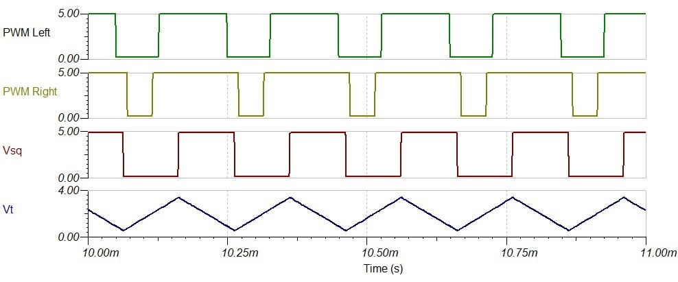
The vehicle uses only analog electronics. The PWM controller works by comparing a triangle wave with the voltage received from the two sensors. The two sensors are adjusted by a voltage divider. When comparing the received voltage with the ramps of the triangular wave, two comparators generate the amplitude modulated pulses.
The triangle wave generator circuit has three blocks. A block that generates a reference voltage that will be half the supply voltage of the circuit. A comparator circuit with hysteresis or Schmitt Trigger that will generate a square wave and an integrating circuit. By integrating the two constants that the square wave gives us, it will generate two ramps, one increasing and then another decreasing, our triangular wave.
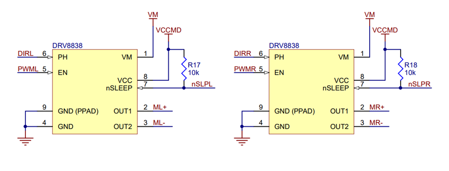
Schematics

R4 = 40 kohm, R6 = 40 kohm. In the PCB R4 = 47 kohm and R6 = 180 kohm, experimental values
Bill of Materials:
| Product Name | Manufacturer | Quantity | |
|---|---|---|---|
| Trimpot, Multi Turn, Cermet, Top Adjust, 50 kohm, Through Hole, 12 Turns | BOURNS | 2 | Buy Now |
|
Through Hole Resistor, 470 kΩ, |
MULTICOMP PRO | 2 | Buy Now |
|
Through Hole Resistor, 10kΩ |
MULTICOMP PRO | 1 | Buy Now |
| Through Hole Resistor, 100 Ω | MULTICOMP PRO | 2 | Buy Now |
| Through Hole Resistor, 120 kΩ | MULTICOMP PRO | 1 | Buy Now |
| Through Hole Resistor, 180 kΩ | MULTICOMP PRO | 1 | Buy Now |
| Through Hole Resistor, 47 kΩ | MULTICOMP PRO | 1 | Buy Now |
| Capacitor, Metallized PET, 0.1 µF | VISHAY | 2 | Buy Now |
| LDR, 1 Mohm, 250 mW, 320 V | ADVANCED PHOTONIX | 2 | Buy Now |
| LM358P Operational Amplifier, 2 Amplifier | TEXAS INSTRUMENTS | Buy Now | |
| MCP6007 2 OpAmps , 1 MHz, 1.9 V/µs, 1.8V to 5.5V, MSOP, 8 Pin | MICROCHIP | 2 | Buy Now |
| OP484 Operational Amplifier, Quad, 4 Amplifier, 4.25 MHz | ANALOG DEVICES | 1 | Buy Now |
|
Wire-To-Board Terminal Block, 3.81 mm, 2 Ways, 26 AWG, 16 AWG, Screw |
MULTICOMP PRO | 4 | Buy Now |
|
Prototyping Board, Eurocard, FR2, Epoxy Paper, 1.5mm, 100mm x 160mm |
ROTH ELEKTRONIK | 1 | Buy Now |
|
LED, Yellow, Through Hole, T-1 3/4 (5mm), 20 mA, 2.1 V, 592 nm |
MULTICOMP PRO | 2 | Buy Now |
|
8 Contacts, DIP Socket, 2.54 mm, |
ARIES | 1 | Buy Now |
|
14 Contacts, DIP Socket, 2.54 mm |
ARIES | 1 | Buy Now |
The OP484 is borrowed from this kit: Digilent - Analogue Part Kit
Alternative Parts:
Initially we started working with two MCP6007. See Op-Amp Line Follower - Blog 1 First Steps
| MCP6007 2 OpAmps , 1 MHz, 1.9 V/µs, 1.8V to 5.5V, MSOP, 8 Pin | MICROCHIP | 2 | Buy Now |
| IC Adapter, Fibreglass, 8-MSOP, 2.54mm Pitch Spacing, 7.62mm Row Pitch | ROTH ELEKTRONIK | 2 | Buy Now |
Chassis and motors:
| Product Name | Manufacturer | Quantity | |
|---|---|---|---|
| Basic Robotic Kit, TI-RSLK Maze Edition, Mobile Platform | ELEMENT14 | 1 | Buy Now |
| Standoff spacers |
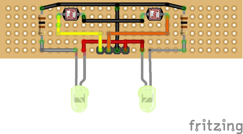
Protoboard
With the help of Fritzing, we tested the layout of the components on the strip prototyping board.

For the prototype we use an Eurocard Prototyping Board , FR2, Epoxy Paper, 1.5mm, 100mm x 160mm, cut so that it does not protrude from the chassis and drilled in 4 places so that it can be fixed to the chassis with standoff spacers.
To cut the tracks that were not supposed to be connected we used a Duratool Track Cutter

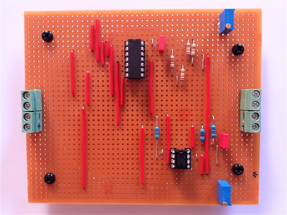
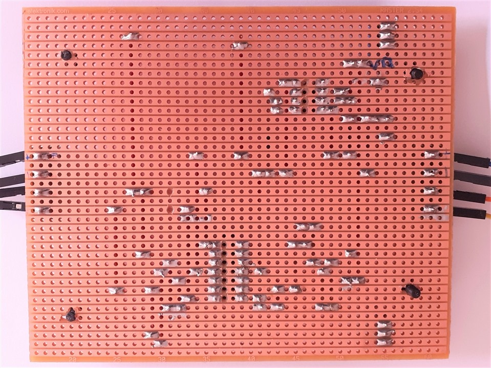
This was the end result once the components were soldered to the prototyping board.
The fine adjustment potentiometers are located at the rear, in the most stable area of the robot so that the robot does not swing and change the distance of the sensors to the ground while adjustments are made.
A potentiometer has been placed to the right and another to the left corresponding to the motor on each side and in a position such that turning clockwise decreases the speed of the motor and turning counterclockwise of the clock increases the speed of the corresponding motor.
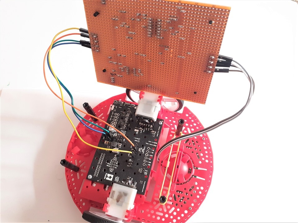
Top view of the control board.
And the back of the board.
The controller board is connected with Dupont cables to the line sensor and to the the Pololu motor driver and power distribution board.
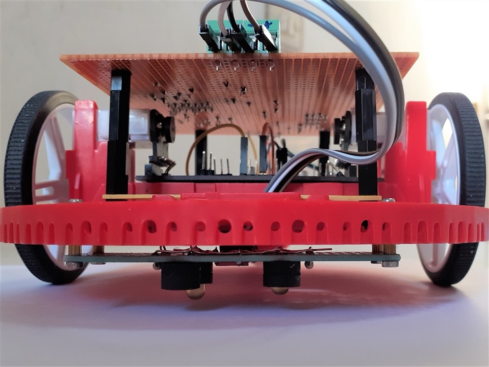
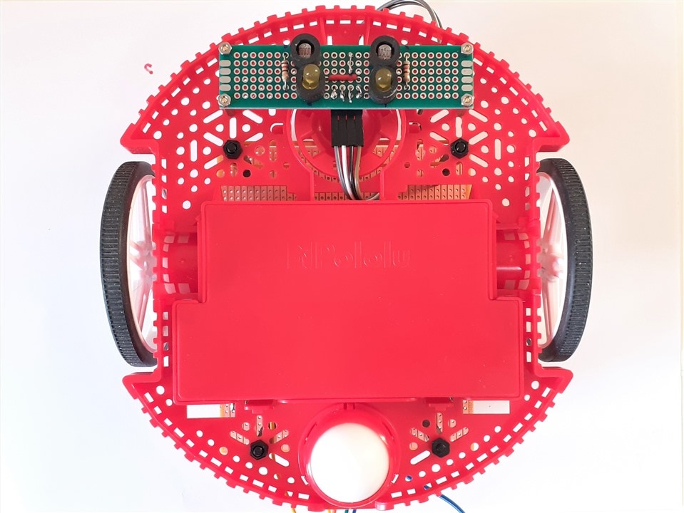
Line sensor board
The line sensor with the two photoresistors and the two yellow LEDs are built on another board.
The line sensor is placed in the lower part of the chassis separated with standoff spacers at a small distance from the surface on which the vehicle is going to navigate. If the surface is not completely smooth, you have to leave more space with the ground.
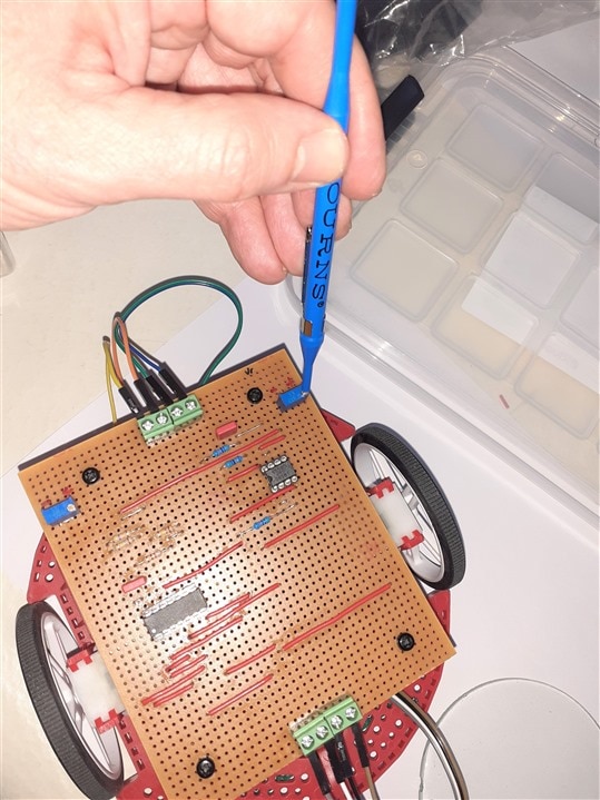
Adjusting sensors sensitivity
Using the two trim-pots you can calibrate the sensitivity of the two sensors. The trim pots form a voltage divider with the photoresistors. You can adjust the input voltage to be between the peaks of the triangle wave. The Trim Pot Adjustment Tool for Bourns Trimmers is very useful for this task. Trim Pot Adjustement Tool
Quality Assurance
The quality assurance team testing the vehicle.
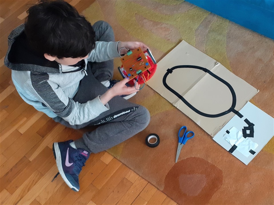
Testing his small circuit:
Trying to fool the line follower
This time the four colored squares along the line act as small traps, swerving the vehicle sharply. Finally the robot corrects the trajectory.
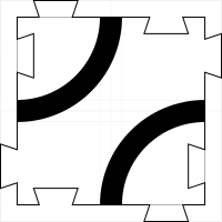
Next Steps: Playing with Line Follower - Puzzle pieces
Playing with the line follower is really fun. To increase its game possibilities, we have decided to create a series of puzzle pieces that allow us to make configurable paths.
The different kinds of puzzle pieces.

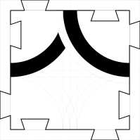


A couple of possible path configurations.


Thanks and conclusion
Thanks to the Project14 team for this opportunity to learn more about op amps and to the community members who have read the blogs and given us feedback and guided us through troubleshooting.

